22email: julien.faure@cea.fr
Thermodynamics of the dead-zone inner edge in protoplanetary disks
Abstract
Context. In protoplanetary disks, the inner boundary between the turbulent and laminar regions could be a promising site for planet formation, thanks to the trapping of solids at the boundary itself or in vortices generated by the Rossby wave instability. At the interface, the disk thermodynamics and the turbulent dynamics are entwined because of the importance of turbulent dissipation and thermal ionization. Numerical models of the boundary, however, have neglected the thermodynamics, and thus miss a part of the physics.
Aims. The aim of this paper is to numerically investigate the interplay between thermodynamics and dynamics in the inner regions of protoplanetary disks by properly accounting for turbulent heating and the dependence of the resistivity on the local temperature.
Methods. Using the Godunov code RAMSES, we performed a series of 3D global numerical simulations of protoplanetary disks in the cylindrical limit, including turbulent heating and a simple prescription for radiative cooling.
Results. We find that waves excited by the turbulence significantly heat the dead zone, and we subsequently provide a simple theoretical framework for estimating the wave heating and consequent temperature profile. In addition, our simulations reveal that the dead-zone inner edge can propagate outward into the dead zone, before staling at a critical radius that can be estimated from a mean-field model. The engine driving the propagation is in fact density wave heating close to the interface. A pressure maximum appears at the interface in all simulations, and we note the emergence of the Rossby wave instability in simulations with extended azimuth.
Conclusions. Our simulations illustrate the complex interplay between thermodynamics and turbulent dynamics in the inner regions of protoplanetary disks. They also reveal how important activity at the dead-zone interface can be for the dead-zone thermodynamic structure.
Key Words.:
Protoplanetary disk - Dead zone - thermodynamic - planet formation1 Introduction
Current models of protoplanetary (PP) disks are predicated on the idea that significant regions of the disk are too poorly ionized to sustain MRI turbulence. These PP disks are thought to comprise a turbulent body of plasma (the ‘active zone’) enveloping a region of cold quiescent gas, in which accretion is actually absent (the ‘dead zone’) (Gammie 1996, Armitage 2011). These models posit a critical inner radius ( au) within which the disk is fully turbulent and beyond which the disk exhibits turbulence only in its surface layers, for a range of radii ( au) (but see Bai & Stone 2013 for a complication of this picture).
The inner boundary between the MRI-active and dead regions is crucial for several key processes. Because there is a mismatch in accretion across the boundary, a pressure maximum will naturally form at this location which (a) may halt the inward spiral of centimetre to metre-sized planetesimals (Kretke et al., 2009), and (b) may excite a large-scale vortex instability (‘Rossby wave instability’) (Lovelace et al., 1999) that may promote dust accumulation, hence planet formation (Barge & Sommeria, 1995; Lyra et al., 2009; Meheut et al., 2012). On the other hand, the interface will influence the radial profiles of the dead zone’s thermodynamic variables — temperature and entropy, most of all. Not only will it affect the global disk structure and key disk features (such as the ice line), but the interface will also control the preconditions for dead-zone instabilities that feed on the disk’s small adverse entropy gradient, such as the subcritical baroclinic instability and double-diffusive instability (Lesur & Papaloizou, 2010; Latter et al., 2010).
Most studies of the interface have been limited to isothermality. This is a problematic assumption because of the pervasive interpenetration of dynamics and thermodynamics in this region, especially at the midplane. Temperature depends on the turbulence via the dissipation of its kinetic and magnetic fluctuations, but the MRI turbulence, in turn, depends on the temperature through the ionization fraction, which is determined by thermal ionization (Pneuman & Mitchell, 1965; Umebayashi & Nakano, 1988). Because of this feedback loop, the temperature is not an additional piece of physics that we add to simply complete the picture; it is instead at the heart of how the interface and its surrounding region work. One immediate consequence of this feedback is that much of the midplane gas inward of 1 au is bistable: if the gas at a certain radius begins as cold and poorly ionized, it will remain so; conversely, if it begins hot and turbulent, it can sustain this state via its own waste heat (Latter & Balbus, 2012). Thus two stable states are available at any given radius in the bistable region. This complicates the question of where the actual location of the dead zone boundary lies. It also raises the possibility that the boundary is not static, and may not even be well defined. Similar models have also been explored in the context of FU Ori outbursts Zhu et al. (2010, 2009a, 2009b).
In this paper we simulate these dynamics directly with a set of numerical experiments of MRI turbulence in PP disks. We concentrate on the inner radii of these disks ( au) so that our simulation domain straddles both the bistable region and the inner dead-zone boundary. Our aim is to understand the interactions between real MRI turbulence and thermodynamics, and thus test and extend previous exploratory work that modelled the former via a crude diffusive process (Latter & Balbus, 2012). Our 3D MHD simulations employ the Godunov code RAMSES (Teyssier, 2002; Fromang et al., 2006), in which the thermal energy equation has been accounted for and magnetic diffusivity appears as a function of temperature (according to an approximation of Saha’s law). We focus on the optically thick disk midplane, and thus omit non-thermal sources of ionization. This also permits us to model the disk in the cylindrical approximation.
This initial numerical study is the first in a series, and thus lays out our numerical tools, tests, and code-checks. We also verify previous published results for fully turbulent disks and disks with static dead zones (Dzyurkevich et al., 2010; Lyra & Mac Low, 2012). We explore the global radial profiles of thermodynamic variables in such disks, and the nature of the turbulent temperature fluctuations, including a first estimate for the magnitude of the turbulent thermal flux. We find that the dead zone can be effectively heated by density waves generated at the dead zone boundary, and we estimate the resulting wave damping and heating. Our simulations indicate that the dead zone may be significantly hotter than most global structure models indicate because of this effect. Another interesting result concerns the dynamics of the dead zone interface itself. We verify that the interface is not static and can migrate from smaller to larger radii. All such simulated MRI ‘fronts’ ultimately stall at a fixed radius set by the thermodynamic and radiative profiles of the disk, in agreement with Latter & Balbus (2012). These fronts move more quickly than predicted because they propagate not via the slower MRI turbulent motions but by the faster density waves. Finally, we discuss instability near the dead zone boundary.
The structure of the paper is as follows. In §2 we describe the setup we used for the MHD simulations and give our prescriptions for the radiative cooling and thermal ionization. We test our implementation of thermodynamical processes in models of fully turbulent disks in §3. There we also quantify the turbulent temperature fluctuations and the turbulent heat flux. Section §4 presents results of resistive MHD simulations with dead zones. Here we look at the cases of a static and dynamic dead zone separately. Rossby wave and other instabilities are briefly discussed in §5; we subsequently summarize our results and draw conclusions in §6.
2 Setup
We present in this paper a set of numerical simulations performed using a version of the code RAMSES (Teyssier, 2002; Fromang et al., 2006) which solves the MHD equations on a 3D cylindrical and uniform grid. Since we are interested in the inner-edge behaviour at the mid-plane, we discount vertical stratification and work under the cylindrical approximation (Armitage, 1998; Hawley, 2001; Steinacker & Papaloizou, 2002). In the rest of this section we present the governing equations, prescriptions, main parameters, and initial and boundary conditions. In order to keep the discussion as general as possible, all variables and equations in this section are dimensionless.
2.1 Equations
Since we are interested in the interplay between dynamical and thermodynamical effects at the dead zone inner edge, we solve the MHD equations, with (molecular) Ohmic diffusion, alongside an energy equation. We neglect the kinematic viscosity, that is much smaller than Ohmic diffusion, because of its minor role in the MRI dynamics. However dissipation of kinetic energy is fully captured by the numerical grid. We adopt a cylindrical coordinate system centred on the central star:
| (1) | |||||
| (2) | |||||
| (3) | |||||
| (4) |
where is the density, is the velocity, is the magnetic field, and is the pressure. is the gravitational potential. In the cylindrical approximation, it is given by where is the gravitational constant and is the stellar mass. In RAMSES, is the total energy, i.e. the sum of kinetic, magnetic and internal energy (but it does not include the gravitational energy). Since we use a perfect gas equation of state to close the former set of equations, the latter is related to the pressure through the relation in which . The magnetic diffusivity is denoted by . As we only consider thermal ionization, will depend on temperature ; its functional form we discuss in the following section. Associated with that resistivity is a resistive flux that appears in the divergence of Eq. (3). Its expression is given by Eq. (23) of Balbus & Hawley (1998). The symbol denotes radiative losses and it will be described in section 2.3. Dissipative and radiative cooling terms are computed using an explicit scheme. This method is valid if the radiative cooling time scale is much longer than the typical dynamical time (see section 2.4). Finally, we have added a source term in the continuity equation that maintains the initial radial density profile (Nelson & Gressel, 2010; Baruteau et al., 2011). It is such that
| (5) |
The restoring time scale is set to local orbits and prevents the long term depletion of mass caused by the turbulent transport through the inner radius.
2.2 Magnetic diffusion
In this paper, we conduct both ideal () and non-ideal () simulations. In the latter case, we treat the disk as partially ionized. In such a situation, the magnetic diffusivity is known to be a function of the temperature and ionization fraction (Blaes & Balbus, 1994):
| (6) |
The ionisation fraction can be evaluated by considering the ionization sources of the gas. In the inner parts of PP disks, the midplane electron fraction largely results from thermal ionization (neglecting radioisotopes that are not sufficient by themselves to instigate MRI). Non thermal contributions due to ionization by cosmic (Sano et al., 2000), UVs (Perez-Becker & Chiang, 2011) and X-rays (Igea & Glassgold, 1999) are negligible because of the large optical thickness of the disk at these radii. In fact, the ionization is controlled by the low ionization potential () alkali metals, like sodium and potassium, the abundance of which is of order smaller than hydrogen (Pneuman & Mitchell, 1965; Umebayashi & Nakano, 1988). Then can be evaluated using the Saha equation. When incorporated into Eq. (6), one obtains the following relation between the resistivity and the temperature:
| (7) |
with a constant. Because of the exponential, varies very rapidly with , and, in the context of MRI activation, can be thought of as a ‘switch’ around a threshold . In actual protoplanetary disks, it is well known that that temperature is around K (Balbus & Hawley, 2000; Balbus, 2011). Taking this into account, and for the sake of simplicity, we use in our simulations the approximation:
| (8) |
where is the activation temperature for the onset of MRI. Note that by taking a step function form for we must neglect its derivative in Eq. (4).
2.3 Radiative cooling and turbulent heating
As we are working within a cylindrical model of a disk, without explicit surface layers, we model radiative losses using the following cooling function:
| (9) |
This expression combines a crude description of radiative cooling of the disk () as well as irradiation by the central star (), in which should be thought of as a measure of the disk opacity (see also section 2.4). In the absence of any other heating or cooling sources, should tend toward , the equilibrium temperature of a passively irradiated disk. In principle, is a function of position and surface density, but we take it to be uniform for simplicity. In practice, we found it has little influence on our results. Turbulence or waves ensure that the simulated temperature is always significantly larger than . The parameter determines the quantity of thermal energy the gas is able to hold. For computational simplicity and to ease the physical interpretation of our results, we take to be uniform. In reality, should vary significantly across the dust sublimation threshold K) (Bell & Lin 1994), but an MRI front will always be much cooler K). As a consequence, the strong variation of will not play an important role in the dynamics. Finally, we omit the radiative diffusion of heat in the planar direction, again for simplicity though in real disks it is an important (but complicated) ingredient.
Our prescription for magnetic diffusion, Eq. (8), takes care of the dissipation of magnetic energy when . However, if the disk is sufficiently hot the dissipation of magnetic energy (as with the kinetic energy) is not explicitly calculated. In this case energy is dissipated on the grid; our use of a total energy equation ensures that this energy is not lost but instead fully transferred to thermal energy. It should be noted that though this is perfectly adequate on long length and time scales, the detailed flow structure on the dissipation scale will deviate significantly from reality.
2.4 Initial conditions and main parameters
Our 3D simulations are undertaken on a uniformly spaced grid in cylindrical coordinates . The grid ranges over , and . Here the key length scale serves as the inner radius of our disk domain and could be associated with a value between 0.2-0.4 au in physical units. Each run has a resolution , which has been shown in these conditions to be sufficient for MHD turbulence to be sustained over long timescales (Baruteau et al., 2011). For completeness, we present a rapid resolution study in appendix D that further strengthens our results.
Throughout this paper, we denote by the value of the quantity at the inner edge of the domain, i.e. at . Units are chosen such that:
where stands for the gas angular velocity at radius . Thus all times are measured in inner orbits, so a frequency of unity correspond to a period of one inner orbit. We will refer to the local orbital time at using the variable .
The initial magnetic field is a purely toroidal field whose profile is built to exhibit no net flux and whose maximum strength corresponds to :
| (10) |
The simulations start with a disk initially in approximate radial force balance (we neglect the small radial component of the Lorentz force in deriving that initial state). Random velocities are added to help trigger the MRI. Density and temperature profiles are initialized with radial power laws:
| (11) |
where and are free parameters. Pressure and temperature are related by the ideal gas equation of state:
| (12) |
where depends on the model and is specified below. We choose , which sets the initial radial profile for the density. During the simulation, it is expected to evolve on the long secular timescale associated with the large-scale accretion flow (except possibly when smaller scale feature like pressure bump appear, see section 4). Quite differently, the temperature profile evolves on the shorter thermal timescale (which is itself longer than the dynamical timescale ). It is set by the relaxation time to thermal equilibrium111One consequence is that the ratio which measures the relative importance of thermal and rotational kinetic energy, is no longer an input parameter, as in locally isothermal simulations, but rather the outcome of a simulation..
As shown by Shakura & Sunyaev (1973), turbulent heating in an accretion disk is related to the component of the turbulent stress tensor :
| (13) |
For MHD turbulence amounts to (Balbus & Papaloizou, 1999):
| (14) |
The notation stands for an azimuthal, vertical and time average, is the flow’s azimuthal deviation from Keplerian rotation. The last scaling in equation (13) assumes such deviations are small, i.e. the disk is near Keplerian rotation. Balancing that heating rate by the cooling function gives a relation for the disk temperature (here we neglect in the cooling function):
| (15) |
Using the standard prescription for illustrative purposes, we write which defines the Shakura-Sunyaev parameter, a constant in the classical disk theory (Shakura & Sunyaev 1973). Since , Eq. (15) suggests that in equilibrium for uniform values. We thus used in our initialization of .
We can use a similar reasoning to derive an estimate for the thermal time-scale. Using the turbulent heating rate derived by Balbus & Papaloizou (1999) and the definition of , the mean internal energy evolution equation can be approximated by
| (16) |
which yields immediately
| (17) |
For , the heating time scale is thus about local orbits. The cooling time-scale is more difficult to estimate, but near equilibrium should be comparable to .
In order to obtain a constraint on the parameter we use the relations , where is the sound speed and is the disk scale height. At approximate thermal equilibrium, Eq. (15), can be used to express as a function of disk parameters:
| (18) |
Now setting (and moving to numerical units) ensures that only depends on the ratio . We investigate two cases: a ‘hot’ disk with which yields , and a ‘cold’ disk with and thus . The two parameter choices for will be referred to as the and cases in the following. Using the relation between pressure and sound speed respectively yields and for the two models. The surface density profile in the simulations is given by a power law:
| (19) |
In resistive simulations, the parameters , and (when applicable) need to be specified for the runs to be completely defined. We used , which means that the temperature in the hot turbulent innermost disk radius is 20 times that of a cold passive irradiated disk. As discussed in section 2.3, is so small that it has little effect on our results. The values of and vary from model to model and will be discussed in the appropriate sections.
In order to assess how realistic our disk model is, we convert some of its key variables to physical units. This can be done as follows. We consider a protoplanetary disk orbiting around a half solar mass star, with surface density g.cm-2 and temperature K at AU (Given the radial profile we choose for the surface density, this would correspond to a disk mass of about seven times the minimum mass solar nebular within 100 AU of the central star). For this set of parameters, we can use Eq. (18) to calculate in cgs units for model , using . In the simulations, the vertically integrated cooling rate is thus given by the cooling rate per unit surface:
| (20) |
This value can be compared to the cooling rate of a typical disk with the same parameters (Chambers, 2009):
| (21) |
where is the Stefan-Boltzman constant and in which cm2.g-1 stands for the opacity. Using these figures, we obtain , i.e. a value that is close (given the level of approximation involved) to that used in the simulations222 With our choice of parameters, we have and . This means that the agreement between and improves with radius. At small radial distances, dust sublimates and our model breaks donwn (see section 6) (see Eq. (20)). We caution that this acceptable agreement should not be mistaken as a proof that we are correctly modelling all aspects of the disk’s radiative physics. The cooling function we use is too simple to give anything more than an idealized thermodynamical model. It only demonstrates the consistency between the thermal timescale we introduce in the simulations and the expected cooling timescale in proto-planetary disks.
2.5 Buffers and boundaries
Boundary conditions are periodic in and while special care has been paid to the radial boundaries. Here , , , are set to zero, is computed to enforce magnetic flux conservation, is set to the Keplerian value, and finally temperature and density are fixed to their initial values.
As is common in simulations of this kind, we create two buffer zones adjacent to the inner and outer boundaries in which the velocities are damped toward their boundary values in order to avoid sharp discontinuities. The buffer zones extend from to for the inner buffer and from to for the outer one. For the same reason, a large resistivity is used in those buffer zones in order to prevent the magnetic field from accumulating next to the boundary. As a result of this entire procedure, turbulent activity decreases as one approaches the buffer zones. This would occasionally mean the complete absence of turbulence in the region close to the inner edge because of inadequate resolution. To avoid that problem, the cooling parameter gradually increases with radius in the region . In appendix A, we give for completeness the functional form of we used. These parts of the domain that corresponds to the inner and outer buffers are hatched on all plots of this paper.
3 MHD simulations of fully turbulent PP disks
We start by describing the results we obtained in the ‘ideal’ MHD limit: throughout the disk. As a consequence, there is no dead zone and the disk becomes fully turbulent as a result of the MRI. The purpose of this section is (a) to describe the thermal structure of the quasi-steady state that is obtained, (b) to check the predictions of simple alpha models, and (c) to examine the small-scale and short-time thermodynamic fluctuations of the gas, especially with respect to their role in turbulent heat diffusion. Once these issues are understood we can turn with confidence to the more complex models that exhibit dead-zones.
3.1 Long-time temperature profiles
We discuss here the results of the two simulations that correspond to and . We evolve the simulations not only for a long enough time for the turbulence transport properties to reach a quasi-steady state but also for the thermodynamic properties to have also relaxed. Thus the simulations are evolved for a time much longer than the thermal time of the gas, local orbits. Here, we average over nearly 1000 inner orbits (about at the outermost radius ).
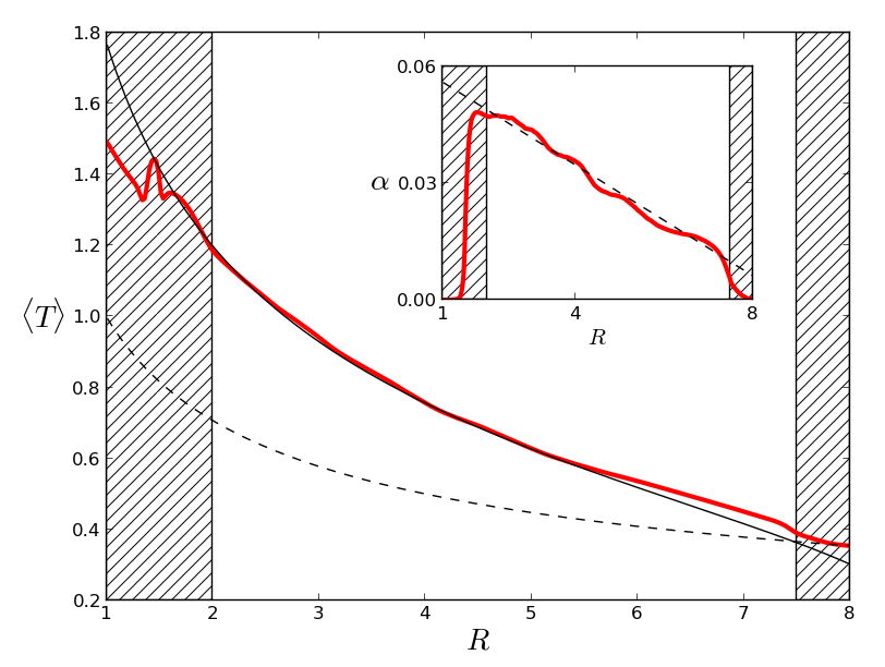
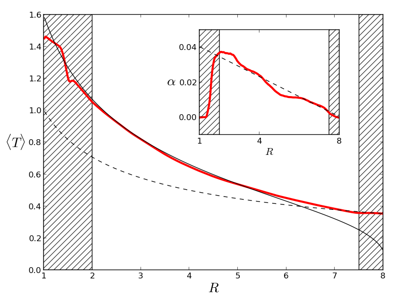
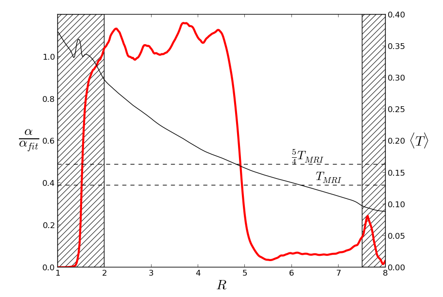
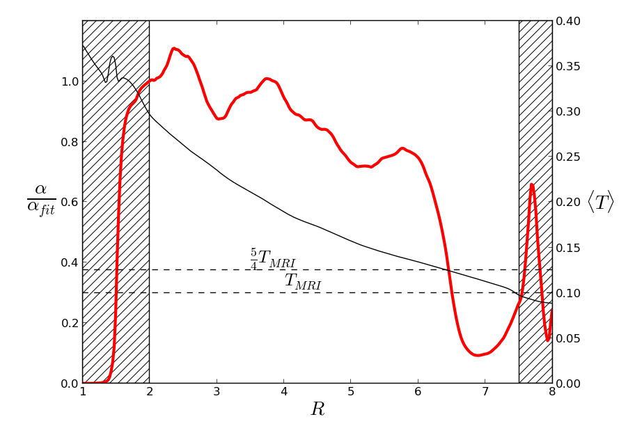
In figure 1 we present the computed radial temperature profiles and the radial profiles of for the two simulations. Note that is clearly not constant in space. In both models, is of order a few times and decreases outward. We caution here that this number and radial profiles are to be taken with care. The value is well known to be affected by numerical convergence (Beckwith et al., 2011; Sorathia et al., 2012) as well as physical convergence issues (Fromang et al., 2007; Lesur & Longaretti, 2007; Simon & Hawley, 2009). This may also influence the temperature because it depends on the turbulent activity.
The disk temperature rapidly departs from the initialized power law given by Eq. (11). In both plots the averaged simulated temperature decreases faster than . This is partly a result of decreasing with radius, and a consequent reduced heating with radius. The disk aspect ratios are close to the targeted values: and in model and respectively, slightly increasing with radius in both cases.
One of our goals is to check the implementation of the thermodynamics, and to ensure that we have reached thermal equilibrium. To accomplish this we compare the simulation temperature profiles with theoretical temperature profiles computed according to the results of Balbus & Papaloizou (1999). The theoretical temperature profile can be deduced from thermal equilibrium, Eq. (15), in which we now include the full expression for the cooling function (i.e. including ):
| (22) |
Using the simulated profiles as inputs, we could then calculate radial profiles for . In fact, we used linear fits of (shown as a dashed line) in Eq. (22), for simplicity. The theoretical curves are compared with the simulation results in figure 1. The overall good agreement validates our implementation of the source term in the energy equation and also demonstrates that we accurately capture the turbulent heating. It is also a numerical confirmation that turbulent energy is locally dissipated into heat in MRI–driven turbulence and that our simulations have been run sufficiently long to achieve thermal equilibrium. During the steady state phase of the simulations, the mass loss at the radial boundaries is very small: the restoring rate is on average on the domain.
3.2 Turbulent fluctuations of temperature
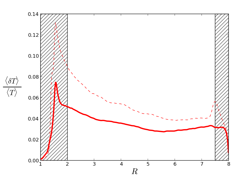
We now focus on the local and short time evolution of , by investigating the fluctuations of density and temperature once the mean profile has reached a quasi steady state. We define the temperature fluctuations by , where an overline indicates an azimuthal and vertical average. The magnitude of the fluctuations are plotted in figure 2. In the case, the fluctuations range between and % while they vary between and % in the case. The smaller temperature fluctuations in the latter case possibly reflect the weaker turbulent transport in the latter case, while also its greater heat capacity. The tendency of the relative temperature fluctuations to decrease with radius is due to decreasing outward.
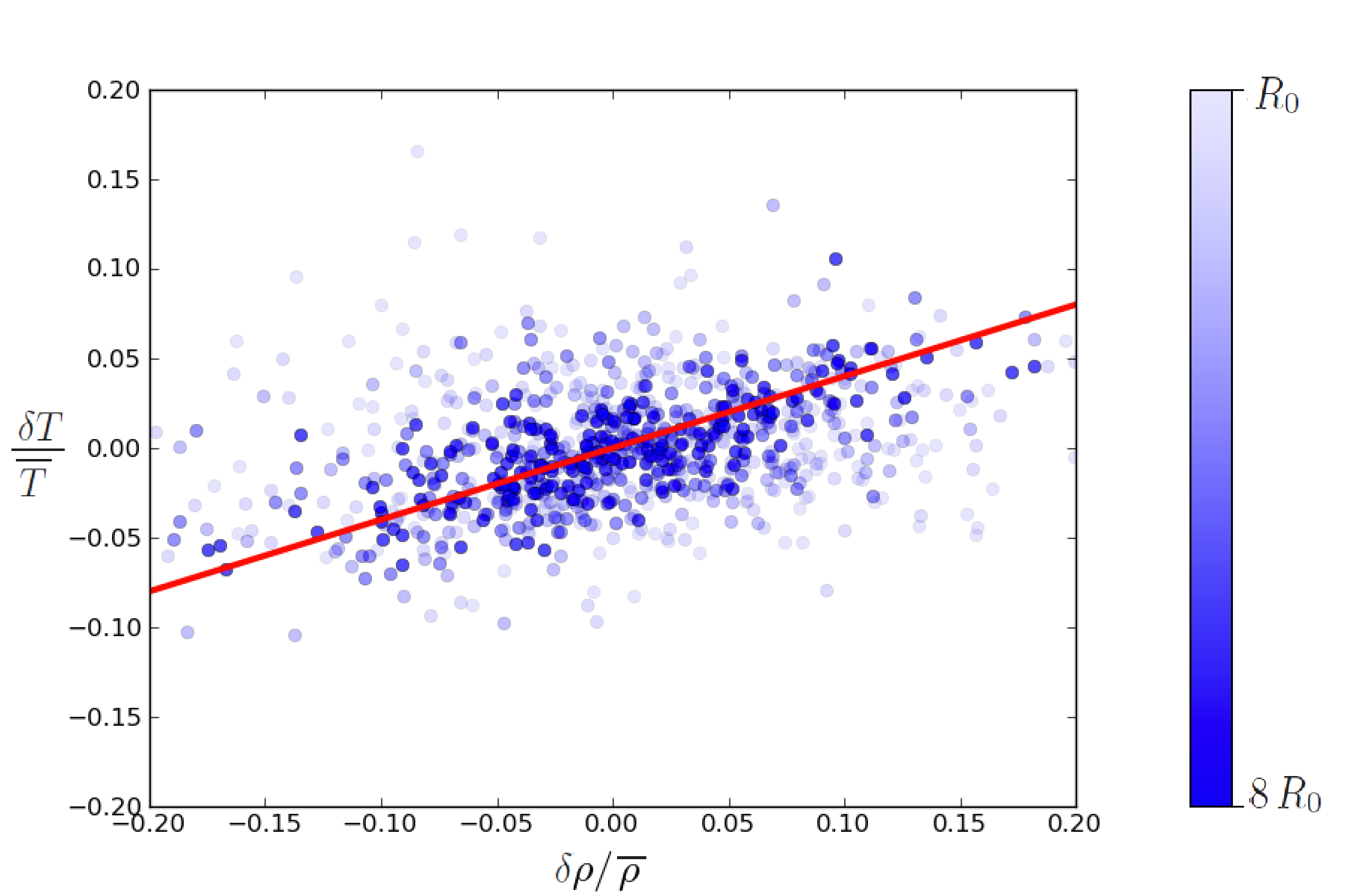
These temperature fluctuations can be due to different kinds of events that act, simultaneously or not, to suddenly heat or cool the gas. Such events can, for example, be associated with adiabatic compression or magnetic reconnection. To disentangle these different possibilities, we note that turbulent compressions, being primarily adiabatic, satisfy the following relationship between and the density fluctuations :
| (23) |
On figure 3 we plot the distribution of a series of fluctuation events randomly selected during the model in the plane. The dot opacity is a function of the event’s radius: darker points stand for outer parts of the disk. The events are scattered around the adiabatic slope (represented with a red line), but display a large dispersion that decreases as radius increases. The difference between the disk cooling time and its orbital period is so large that the correlation should be much better if all the heating/cooling events were due to adiabatic compression. This implies that temperature fluctuations are mainly the result of isolated heating events such as magnetic reconnection. This suggestion is supported by the larger dispersion at short distance from the star, where turbulent activity is largest. However, a detailed study of the heating mechanisms induced by MRI turbulence is beyond the scope of this paper. Indeed, the low resolution and the uncontrolled dissipation at small scales – important for magnetic reconnection – both render any detailed analysis of the problem difficult. Future local simulations at high resolution and with explicit dissipation will be performed to investigate that question further.
As shown in Balbus (2004), MHD turbulence may also induce thermal energy transport through correlations between the temperature fluctuations and velocity fluctuations . For example, the radial flux of thermal energy is given by Eq. (5) of Balbus (2004):
| (24) |
By analogy with molecular thermal diffusivity, we quantify the turbulent efficiency to diffuse heat using a parameter :
| (25) |
To make connection with standard disk models, we introduce the parameter which is a dimensionless measure of :
| (26) |
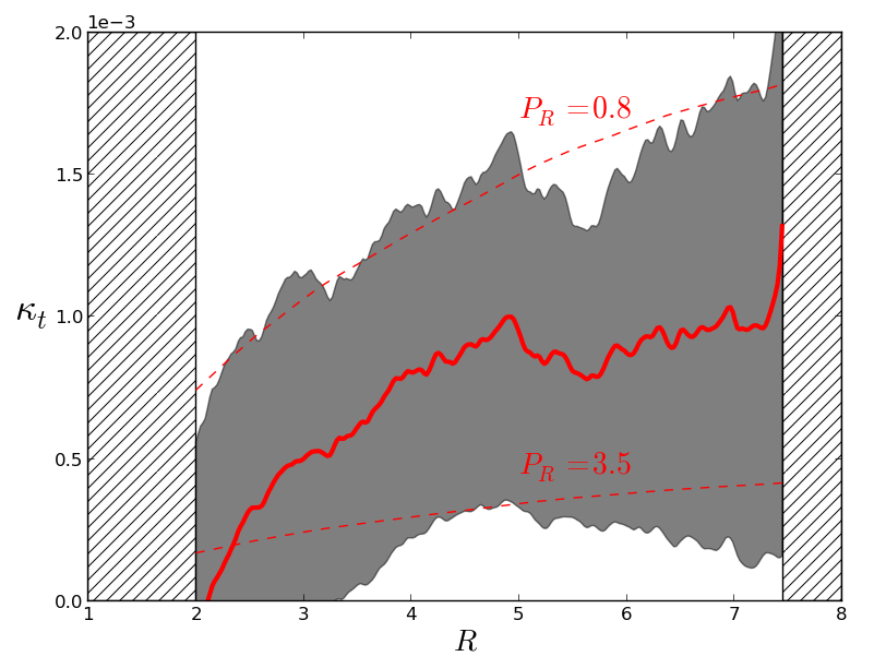
as well as the turbulent Prandtl number that compares turbulent thermal and angular momentum transports. We measure the turbulent thermal diffusivity in the model and plot in figure 4 its radial profile and statistical deviation. For comparison, we also plot two radial profiles of that would result from constant , chosen such that they bracket the statistical deviations of the simulations results. They respectively correspond to and (assuming a constant ). The large deviation around the mean value prevents any definitive and accurate measurement of , but our data suggest that is around unity. This is relatively close to that Pierens et al. (2012) used to investigate, with a diffusive model, how the turbulent diffusivity impacts on planet migration.
Turbulent diffusion must be compared to the radiative diffusion of temperature. In the optically thick approximation, the radiative diffusivity is . One can establish, using Eq. (15), that the dimensionless measure of radiative diffusivity , defined similarly to (see Eq. (25) and Eq. (26)), is equal to a few . The turbulent transport of energy is then comparable to radiative transport in PP disks (see also Appendix A in Latter & Balbus 2012). Nevertheless, radiative transport is neglected in our simulations. As indicated by the discussion above, this shortcoming should be rectified in future. Note that radiative MHD simulations are challenging and Flock et al. (2013) performed the first global radiative MHD simulations of protoplanetary disks only very recently. Previous studies had been confined to the shearing box approximation (Hirose et al., 2006; Flaig et al., 2010; Hirose & Turner, 2011) because of the inherent numerical difficulties of radiative simulations.
4 MHD simulations of PP disks with a dead zone
We now turn to the non-ideal MHD models in which the disk is composed of an inner turbulent region and a dead zone at larger radii. To make contact with previous work (Dzyurkevich et al., 2010; Lyra & Mac Low, 2012), we first consider the case of a resistivity that is only a function of position. Such a simplification is helpful to understand the complex thermodynamics of the dead zone before moving to the more realistic case in which the resistivity is self-consistently calculated as a function of the temperature using Eq. (8).
4.1 The case of a static interface
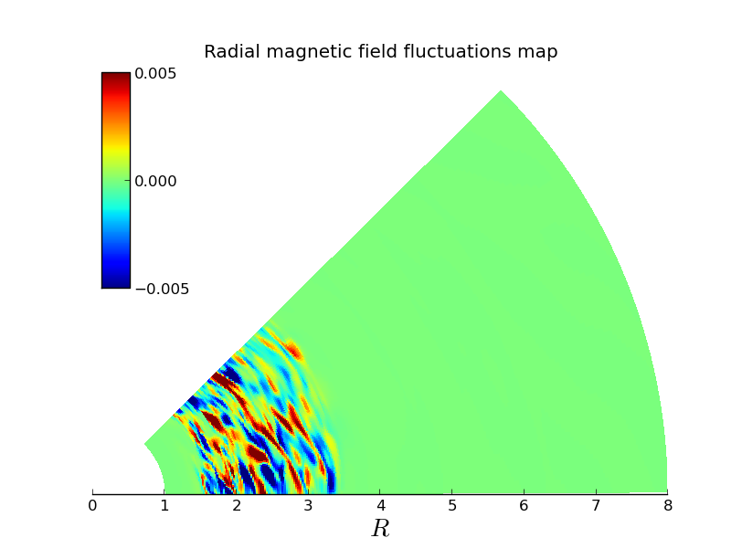
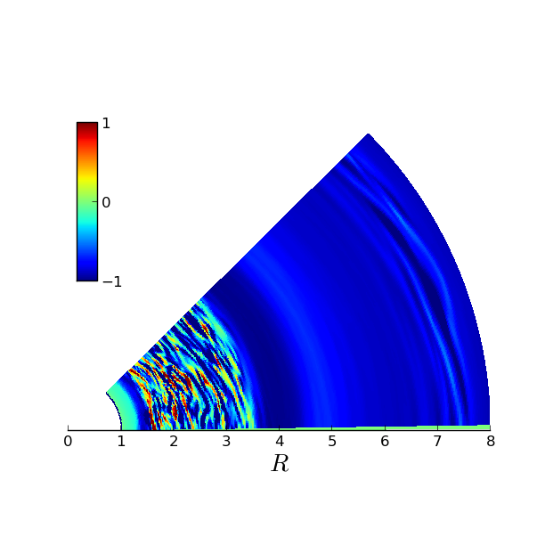
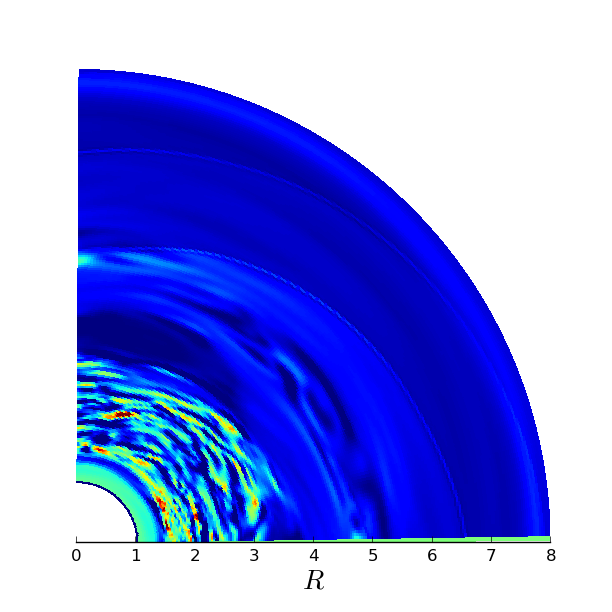
At , model has reached thermal equilibrium. We then set for , and for , and restart the simulation. The higher value of corresponds to a magnetic Reynolds number . It is sufficient to stabilize the MRI, and as expected, the flow becomes laminar outward of in a few orbits. The structure of the flow after inner orbits (which roughly amounts to one cooling time at ) is shown in figure 5. The left panel shows a snapshot of the radial magnetic field. The turbulent active region displays large fluctuations which can easily be identified. The interface between the active and the dead zone, defined as the location where the Maxwell stress (or, equivalently, the magnetic field fluctuations) drops to zero, stands at until the end of this static non-ideal simulation.
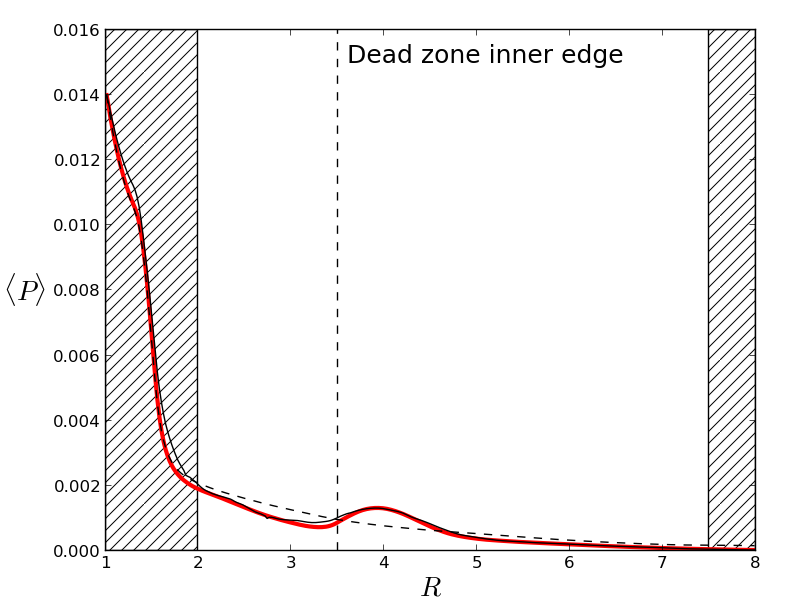
As soon as the turbulence vanishes, the sharp gradient of azimuthal stress at the interface drives a strong radial outflow. As identified by Dzyurkevich et al. (2010) and Lyra & Mac Low (2012), we observe the formation of a pressure and a density maximum near the active/dead interface. In figure 6, we present the mean pressure perturbation we obtained in that simulation. The growth time scale of that structure is so short that the source term in the continuity equation (see section 2.1) has no qualitative impact because it acts on the longer time scale . This feature persists even after we freeze the temperature and use a locally isothermal equation of state as shown by the black solid line. We conclude that pressure maxima are robust features that form at the dead zone inner edge independently of the disk thermodynamics.
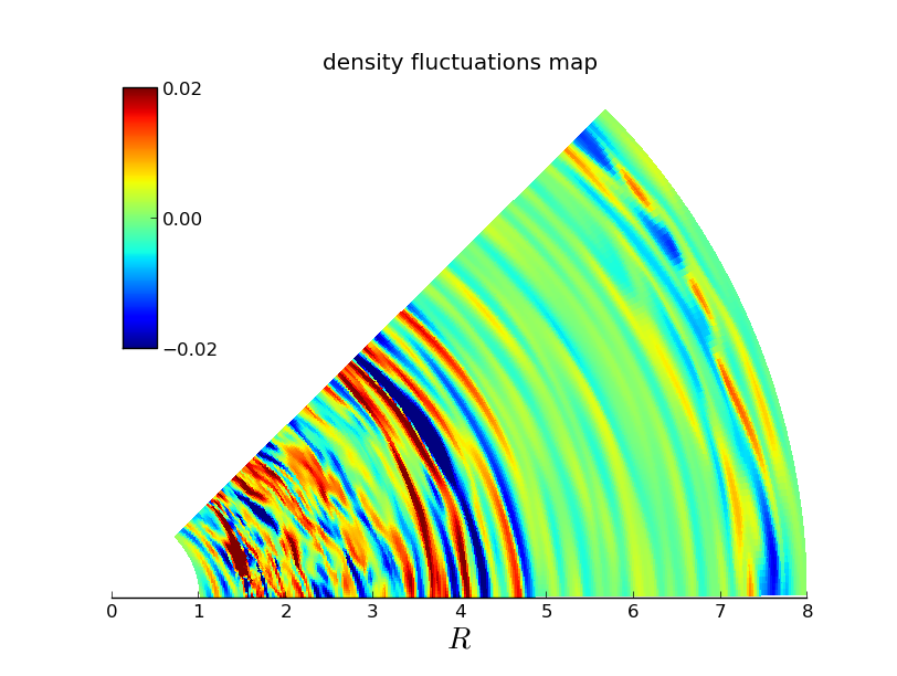
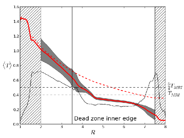
We next turn to the temperature’s radial profile. Because we expect the dead zone to be laminar, we might assume the temperature to drop to a value near (see section 2.3). However, the time averaged temperature radial profile plotted in figure 7 shows this is far from being the case. The temperature in the bulk of the dead zone levels off at , significantly above . This increased temperature cannot be attributed to Ohmic heating, since the magnetic energy is extremely small outward of (at , the magnetic energy has dropped by a factor of compared to , while at it has been reduced by about ). In contrast, there are significant hydrodynamic fluctuations in the dead zone, as shown on the right panel of figure 5. For example, density fluctuations typically amount to of the order of a few percent at . The spiral shape of the perturbation indicate that these perturbations could be density waves propagating in the dead zone, likely excited at the dead/active interface. Such a mechanism would be similar to the excitation of sound waves by the active surface layers observed in vertically stratified shearing boxes simulations (Fleming & Stone, 2003; Oishi & Mac Low, 2009) and also the waves seen in global simulations such as ours (Lyra & Mac Low, 2012) but performed using a locally isothermal equation of state. However, as opposed to Lyra & Mac Low (2012), the Reynolds stress associated with this waves is smaller in the dead zone than in the active zone, and amounts to . Such a difference is likely due to the smaller azimuthal extent we use here, as it prevents the appearance of a vortex (see section 5.1 and Lyra & Mac Low, 2012).
4.2 Wave dissipation in the dead-zone
It is tempting to use Eq. (22) to estimate the temperature that would result if the wave fluctuations were locally dissipated into heat (as is the case in the active zone). However, we obtain which significantly underestimates the actual temperature. This is probably because the density waves we observe in the dead zone do not dissipate locally. We now explore an alternative model that describes their effect on the thermodynamic structure of the dead zone.
We assume that waves propagate adiabatically before dissipating in the form of weak shocks in the dead zone; this assumption is consistent with measured Mach numbers () in the bulk of our simulated dead zone. A simple model for the weak shocks, neglecting dispersion, yields a wave heating rate :
| (27) |
where stands for the wave frequency (Ulmschneider, 1970; Charignon & Chièze, 2013). The derivation of that expression is presented in appendix B. Balancing that heating by the local cooling rate yields an estimate of the temperature’s radial profile.
| (28) |
where the relation between the pressure and the disk scale height has been used. This expression provides an estimate of the dead-zone temperature. If one assumes that the waves are excited around the dead-zone interface, the frequency should be of order the inverse of the correlation time of the turbulent fluctuations at that location. Such a short period for the waves, much shorter than the disk cooling time, is consistent with the hypothesis that these waves behave adiabatically. Local simulations of Fromang & Papaloizou (2006) suggest . Given the units of the simulations, this means that we should use . Taking and , this gives , at , which agrees relatively well with the measured value. The agreement certainly supports the assumption that waves are generated at the interface.
In order to make the comparison more precise, we plot in figure 7 the radial profile of the temperature, computed using Eq. (28)333We used the azimuthally and temporally averaged simulation data for and when computing the temperature using Eq. (28). The agreement with the temperature we measure in the simulation is more than acceptable in the bulk of the dead zone. There are however significant deviations at , i.e. next to the outer boundary. Associated with these deviations, we also measured large, but non wave–like values of the quantity at that location (see figure 5).
In order to confirm that the outer-buffer zone is responsible for these artefacts, we ran an additional simulation with identical parameters but with a much wider radial extent. The outer-radial boundary is located at , and thus the outer-buffer zone extends from to . The additional simulation shows that indeed the suspicious temperature bump moves to the outer boundary again. The temperature in the bulk of the dead zone, on the other hand, remains unchanged and is in good agreement with the model . Further details of this calculation are given in Appendix C.
In Appendix C we show that the density wave theory can also account for the density fluctuations as a function of radius. As waves propagate, their amplitudes decrease, not least because their energy content is converted into heat. Overall, the good match we have obtained between the wave properties’ radial profiles (both for the temperature and density fluctuations) and the analytical prediction strongly favour our interpretation that density waves are emitted at the active/dead zone interface and rule out any numerical artefacts that might be associated with the domain outer boundary.
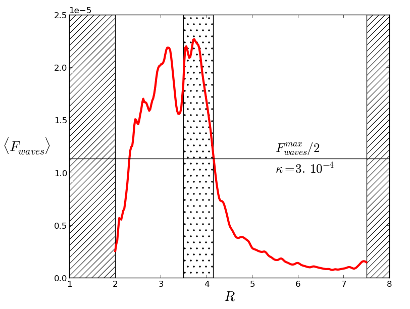
The effect of the waves can be viewed as a flux of thermal energy carried outward. Such a thermal flux can be quantified using Eq. (24) and its radial profile in model is shown in figure 8. It is positive and decreasing in the dead zone which confirms that thermal energy is transported from the active zone and deposited at larger radii. While it is rapidly decreasing with , the important point of figure 8 is that it remains important in a percolation region outward of the dead zone inner edge (located at ). Most of the wave energy that escapes the active region is transmitted to the dead zone over a percolation length, the size of the percolation region. We define the percolation region as the region inside the dead zone where the thermal transport amounts to more that half its value in the active zone. As shown by figure 8, the percolation length in model , which translates to about one scale height at that location.
Though the heat flux is greatest within about of the dead zone interface, the action of the density waves throughout our simulated dead zone keeps temperatures significantly higher than what would be the case in radiative equilibrium. This would indicate that much of the dead zone in real disks would be hotter than predicted by global structure models that omit this heating source. In particular, this should have important implications for the location of the ice line, amongst other important disk features.
4.3 The case of a dynamic interface
We now move to the main motivation of this paper. At we restart model but close the feedback loop between turbulence and temperature. The resistivity is now given by Eq. (8) with . We set the temperature threshold to the value , i.e. slightly above the typical temperature in the dead zone (which is about as discussed above). This set-up ensures that at least half of the radial domain is ‘bistable’, i.e. gas at the same radius can support either one of two quasi-steady stable states, a laminar cold state, and a turbulent hot state.
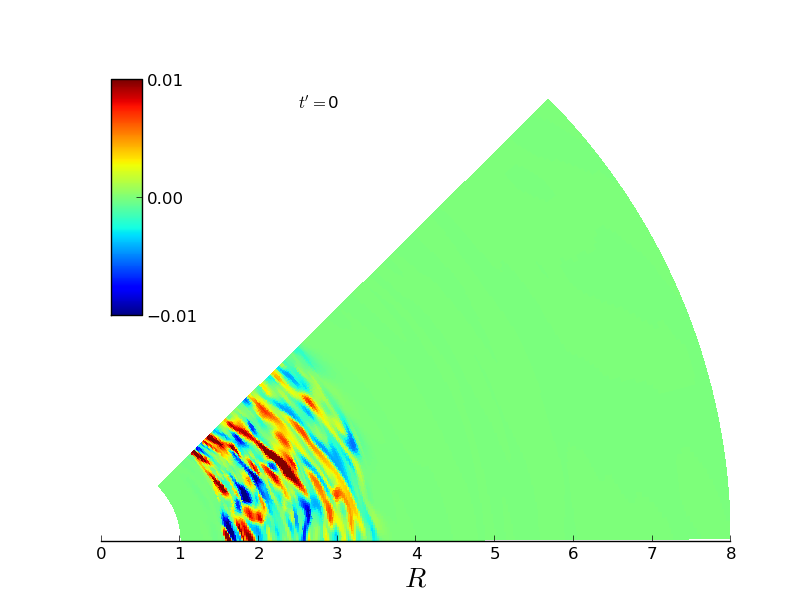
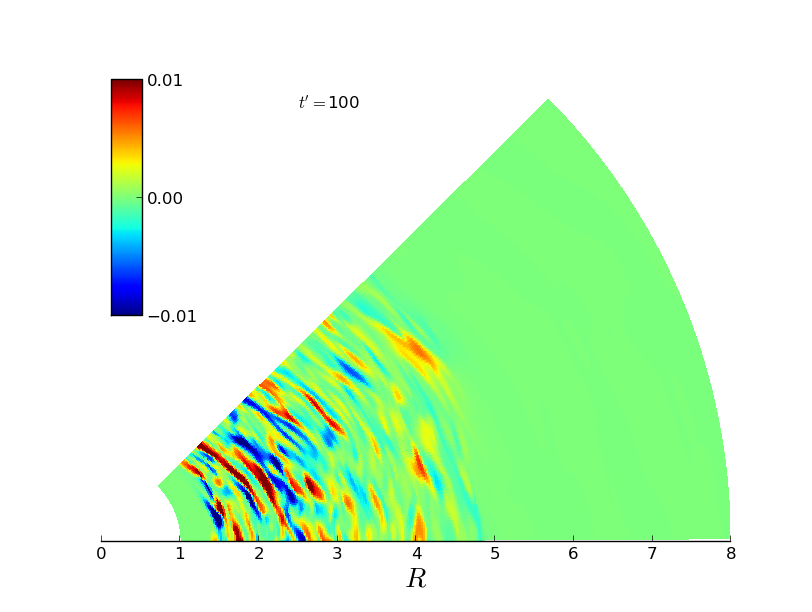
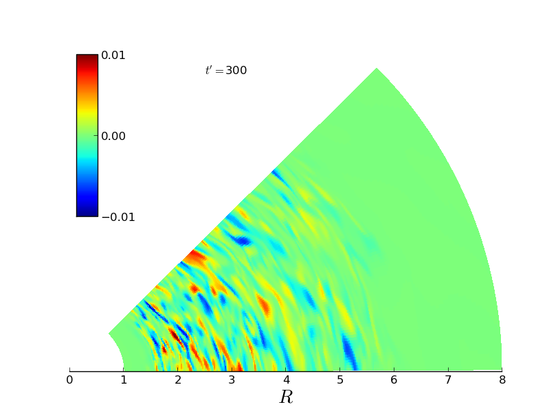
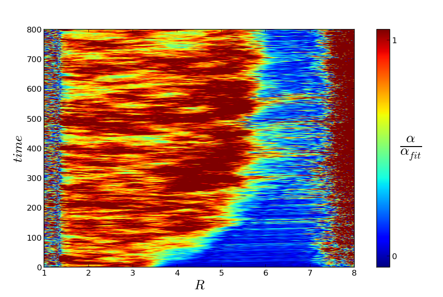
As seen in figure 7, the temperature exceeds in the region at restart. Thus, we would naively expect the interface to move to . As shown by snapshots of the radial magnetic field fluctuations in the plane at three different times on figure 9, indeed the front moves outwards. In doing so, it retains its coherence. However, as shown by the third panel of figure 9, the turbulent front does not stop at but moves outward all the way to –. This is confirmed by the left panel of figure 10, in which a space-time diagram of indicates that the front reaches its stagnation radius in a few hundred orbital periods. 444 To check that Eq. (8) is an acceptable simplification of the actual exponential dependence of with temperature, we ran an additional simulation, with the same parameters as for the but using Eq. (7) for . We find no difference with our fiducial model: the front propagates equally fast and stops at , i.e. almost the same radius as for the case. The following questions arise: can we predict the stalling radius? And can we understand this typical timescale? What can it tell us about the physical mechanism of front propagation?
Stalling radius:
we use the mean field model proposed by Latter & Balbus (2012) to interpret our results. The front-stalling radius can be calculated from the requirement that the integrated cooling and heating across the interface balance each other:
| (29) |
in which and stand for the temperature in the dead zone and in the active zone respectively. While the cooling part of the integral is well defined, the heating part is more uncertain. It is probably a mixture of turbulent heating (with an effective parameter that varies across the front) and wave heating such as described in section 4.1. For simplicity, we adopt the most naive approach possible and assume that is a constant within the front (equal to ) as long as the temperature is larger than , and vanishes otherwise. In that situation, we obtain, similarly to Latter & Balbus (2012) that the stalling radius is determined by the implicit relation:
| (30) |
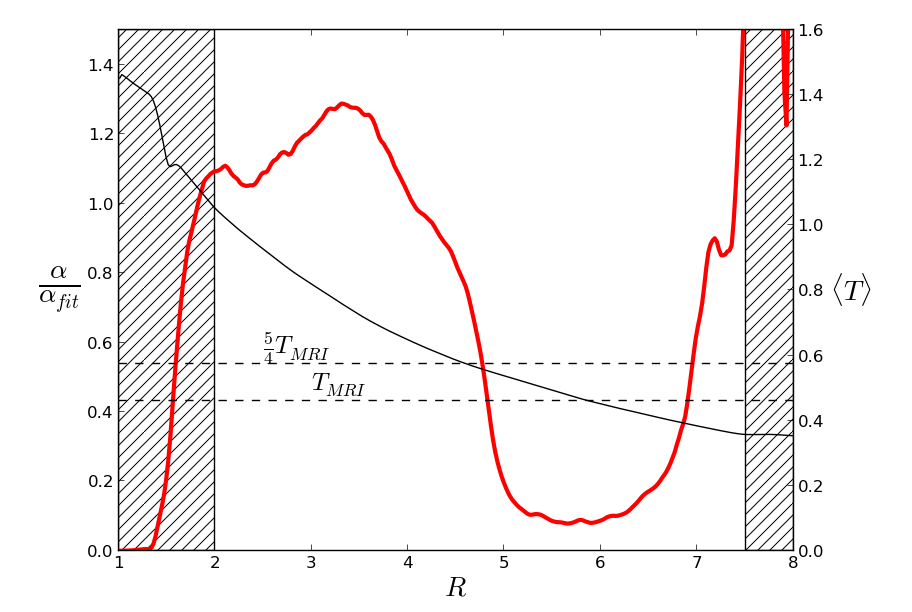
In figure 7, we draw two horizontal lines that correspond to and . The condition given by Eq. (30) is satisfied for which is very close to the critical radius actually reached in simulations (see figures 9 and the left panel of figure 10).
In order to investigate the robustness of this result, we have carried a further series of numerical experiments. First, we have repeated model using a value of (instead of ). According to figure 7, we expect the interface now to propagate over a smaller distance. As shown by the left hand side panel of figure 11, this is indeed the case: the front stalls at which is precisely the position where .
We also computed two analogues of those models with . This was done as follows: after the ideal MHD simulations has reached a quasi thermal equilibrium (), we introduced a static dead zone from to the outer boundary of the domain and we restarted this simulation. We waited for thermal equilibrium to close the feedback loop at . We used . A front propagates until the critical radius . It is as fast as the front of the case. We show in the middle panel of figure 11 that, in accordance with the previous result, the front stops close to the critical radius predicted by Eq. (30). We repeated the same experiment using and show on the right panel of figure 11 that the front stalling radius is again accounted for by the same equation.
To summarize, the front stops close to the predicted value in every simulations we performed. This shows that the equilibrium position of a dead zone inner edge can be predicted as a function of the disk’s radiative properties and thermal structure. It is robust, and in particular does not depend on the details of the turbulent saturation in our simulations (such as the radial profile).
Front speed and propagation:
the previous result is based on dynamical systems arguments. A front is static at a given radial location if the attraction of the active turbulent state balances the attraction of the quiescent state. However, the argument does not help us identify the front propagation speed. In order to understand its dynamics, we ran a set of mean field simulations akin to the ‘slaved model’ in Latter & Balbus (2012) but using parameters chosen to be as close as possible to model . We solve the partial differential equation for the temperature (we have dropped the overbar here for clarity):
| (31) |
To solve that equation, we have used the heating term measured during the ideal MHD simulation (see section 3). The thermal transport of energy is modeled by a simple diffusive law that is supposed to account for turbulent transport. As discussed in section 4.1, the dead zone is heated by waves excited at the dead/active interface. It is thus highly uncertain (and one of the purpose of this comparison) whether a diffusive model adequately describes heat transport of this fashion. The value for is chosen so heat diffusion gives the same mean flux of thermal energy as measured in our simulation (shown in figure 8). We have simplified the radial profile in that plot and have assumed that the thermal flux vanishes outward of the percolation region but is uniform in the active zone and in the percolation region:
| (32) |
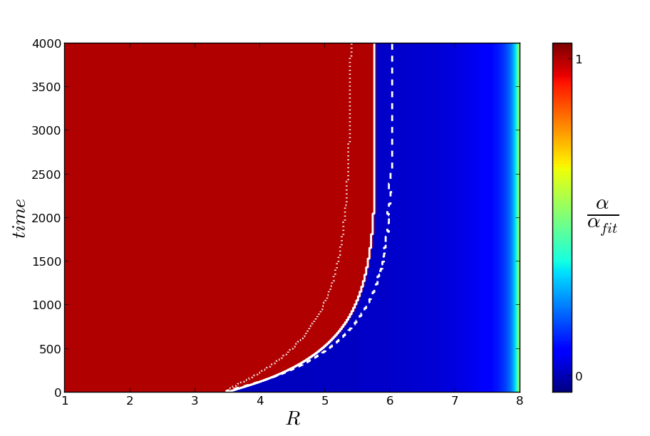
The front location is evaluated at each time step. It is the smallest radius where . As in the MHD simulation, we used and . When , we have found the dead zone inner edge is static regardless of the value of . As expected, the front displacement requires the active and the dead zone to be thermally connected. We have thus used a percolation length and a value of in the active part of the disk which matches the thermal flux at the outer edge of the percolation region (see figure 8). The simulation is initialized with the same physical configuration as the MHD simulation: a dead zone extends from to and is in thermal equilibrium. As shown on the right panel of figure 10, we find that a front propagates outward. The critical radius is in agreement with the results of the simulation and with the argument based on energy conservation detailed above. However, there is clearly a difference in the typical timescale of the propagation: the front observed in the MHD simulation propagates five time faster than the front obtained in the mean field simulation.
In order to check the sensitivity of this results to some of the uncertain aspects of the mean field model, we have run three additional mean field simulations similar to that described above. In these additional models, we change one parameter while keeping all others fixed. In the first model, we have changed the minimum value of the temperature (this is a crude way to model the effect of the dead zone heating at long distances from the interface). In the second model, we have used . In the last model, we have used , thereby extending turbulent heat transport to the entire radial extent of the simulation. The results are shown on the right panel of figure 10: in all cases, the front propagates outward slower than observed in the MHD simulation.
A slow front velocity is thus a generic feature of the diffusive approximation to heat transport. But conversely, it reveals that the fast fronts mediated by real MRI turbulence are controlled by non-diffusive heat transport. This in turn strongly suggests that the front moves forward via the action of fast non-local density wave heating, and not via the slow local turbulent motions of the MRI near the interface, as originally proposed by Latter & Balbus (2012). The transport via density waves occurs at a velocity of order . Thus, it takes a time for thermal energy to be transported through the percolation length . This is shorter than the typical diffusion time over the same distance at , for the values of used in Eq (31).
5 Instability and structure formation
Other issues that can be explored through our simulations are instability and structure formation at the dead/active zone interface and throughout the dead-zone. The extremum in pressure at the interface is likely to give rise to a vortex (or Rossby wave) instability (Lovelace et al., 1999; Varnière & Tagger, 2006; Meheut et al., 2012). On the other hand, the interface will control both the midplane temperature and density structure throughout the dead zone; it hence determines the magnitude of the squared radial Brunt-Väisälä frequency . The size and sign of this important disk property is key to the emergence of the subcritical baroclinic instability and resistive double-diffusive instability in the dead zone (Lesur & Papaloizou, 2010; Latter et al., 2010; Klahr & Bodenheimer, 2003; Petersen et al., 2007b, a). In this final section we briefly discuss these instabilities, leaving their detailed numerical analysis for a future paper.
5.1 Rossby wave instability
The Rossby wave instability has been studied recently by Lyra & Mac Low (2012) with MHD simulations that use a locally isothermal equation of state and a static dead zone. Vortex formation mediated by the Rossby wave instability was reported: a pressure bump forms at the interface which then triggers the formation of a vortex. It is natural to wonder how these results are modified when better account is made of the gas thermodynamics.
In our simulations of a static dead zone (section 4.1), we also find that pressure maxima form. Even with a dependent , the bumps survive as the interface travels to its stalling radius. Moreover, the amplitude of the pressure bump is not modified compared to those observed in simulations of static dead zones. On account of the reduced azimuthal extend of our domains, no large-scale vortices formed. (The reduced azimuth was chosen so as to minimize the computational cost of our simulations.) In order to observe the development of the Rossby wave instability we performed one run identical to the simulation except we extended the azimuthal domain: . The was a given function of position as in Section 4.1, thus the dead/active zone interface was fixed. The right panel of figure 12 shows a late snapshot of this run, in which a vortex has appeared similar to those observed by Lyra & Mac Low (2012). It survives for many dynamical timescales. Consistent with the results of Lyra & Mac Low (2012), we measure in the dead zone. This is two orders of magnitude larger than in the model. The dead zone is consequently much hotter in this simulation, which means the vortex plays a crucial role in both accretion and the thermal physics of the dead zone. Simulations are currently underway to investigate the robustness of this results and the vortex survival when we close the feedback loop (setting ). This will be the focus of a future publication.
5.2 Subcritical baroclinic and double-diffusive instabilities
Another potentially interesting feature of the interface is the strong entropy gradient that might develop near the interface. It could also impact on the stability of the flow on shorter scales, giving rise potentially to the baroclinic instability (Lesur & Papaloizou, 2010; Raettig et al., 2013) or to the double–diffusive instability (Latter et al., 2010). Both instabilities are sensitive to the sign and magnitude of the entropy gradient, which is best quantified by the Brunt-Väisälä frequency :
| (33) |
In general, we find that takes positive values of order – of the angular frequency squared. Negative values sometimes appear localized next to the interface. Positive values rule out both the baroclinic instability and the double–diffusive instability, and indeed, we see neither in the simulations. However, we caution against any premature conclusions about the prevalence of these instabilities in real disk. First, the source term in the continuity equation might alter the density radial profile and, consequently, the Brunt-Väisälä frequency in the dead zone. Second, it is well known that these instabilities are sensitive to microscopic heat diffusion. We do not include such a process explicitly in our simulations. Instead, there is numerical diffusion of heat by the grid, the nature of which may be unphysical. Both reasons preclude definite conclusions at this stage. Dedicated and controlled simulations are needed to assess the existence and nonlinear development of these instabilities in the dead zone.
6 Conclusion
In this paper, we have performed non-ideal MHD simulations relaxing the locally isothermal equation of state commonly used. We have shown the active zone strongly influences the thermodynamic structure of the dead zone via density waves generated at the interface. These waves transport thermal energy from the interface deep into the dead zone, providing the dominant heating source in its inner . As a consequence, the temperature never reaches the very low level set by irradiation. In the outer regions of the dead-zone, however, temperatures will be set by the starlight reprocessed by the disk’s upper layers (Chiang & Goldreich, 1997; D’Alessio et al., 1998). It is because the wave generation and dissipation is located at the midplane that waves should so strongly influence the thermodynamic structure of the dead zone. Note also that density waves generated by the dead/active zone edge are stronger than those excited by the warm turbulent upper layers of the disk as seen in stratified shearing box (Fleming & Stone, 2003).
Another result of this paper concerns the dynamical behaviour of the dead-zone inner edge. We find the active/dead interface propagates over several (i.e. a few tens of an AU) in a few hundreds orbits.All the simulated MRI fronts reached a final position that matched the prediction made by a mean field approach (Latter & Balbus, 2012), which appeals to dynamical systems arguments. As the gas here is bistable, it can fall into either a dead or active state; the front stalls at the location where the nonlinear attraction of the active and dead states are in balance. In contrast, the mean-field model fails to correctly predict the velocity of the simulated fronts. We find that a diffusive description of the radial energy flux yields front speeds that are too slow. In fact, the simulations show that fronts move rapidly via the efficient transport of energy by density waves across the interface. Fronts do not propagate via the action of the slower MRI-turbulent motions.
In addition, we have used our simulations to probe the thermal properties of turbulent PP disks. We have constrained the turbulent Prandtl number of the flow to be of order unity. We have also quantified the turbulent fluctuations of temperature: they are typically of order a few percent of the local temperature. However, their origin – adiabatic compression vs. reconnection – is difficult to assess using global simulations. In-depth dedicated non-isothermal shearing-box simulations will help to distinguish the dominant cause of the temperature fluctuations. Finally, we have made a first attempt to estimate the radial profile of the radial Brunt-Väisälä frequency in the dead zone. This quantity is the key ingredient for the development of both the subcritical baroclinic instability and the resistive double-diffusive instability. We find that can take both positive and negative values at different radii; but we caution that these preliminary results require more testing with dedicated simulations.
Several improvements are possible and are the basis of future work. As discussed in section 5, one obvious extension is to investigate the fate and properties of emergent vortices at the dead-zone inner edge. This can be undertaken with computational domains of a wider azimuthal extent. Such simulations may investigate the role of large-scale vortices, and the waves they generate, on the thermodynamic structure of the dead-zone. They can also observe any feedback of the thermodynamics on vortex production and evolution. We also plan to investigate other magnetic field configurations. For example, vertical magnetic fields might disturb the picture presented here because of the vigorous channel modes that might develop in the marginal gas at the dead-zone edge (Latter, Fromang, & Gressel, 2010). Such an environment may militate against the development of pressure bumps and/or vortices.
Our results, employing the cylindrical approximation, represents a thin region around the PP disk midplane. These results must be extended so that the vertical structure of the disk is incorporated. An urgent question to be addressed is the location of density wave dissipation in such global models. Waves can refract in thermally stratified disks and deposit their energy at the midplane or in the upper layers depending on the type of wave and the stratification (Bate et al. 2002, and references therein). In particular, Bate et al. demonstrate that large-scale axisymetric (and low ) density waves (f modes) propagate upwards, as well as radially, until they reach the upper layers of the disk, at which point they transform into surface gravity waves and propagate along the disk surface. But this is only shown for vertically polytropic disks in which the temperature decreases with and for waves with relatively low initial amplitudes. In PP-disk dead zones we expect the opposite to be the case, and it is uncertain how density waves behave in this different environment.
Finally, in this work we have increased the realism of one aspect of the physical problem, the dynamics of the turbulence, (via direct MHD simulations of the MRI), but have greatly simplified the physics of radiative cooling. As a result, the simulations presented here are still highly idealized and several improvements should be the focus of future investigations. For example, our approach completely neglects the fact that dust sublimates when the temperature exceeds K. As a result, the opacity drops by up to four orders of magnitude with potentially dramatic consequences for the disk energy budget (leading to a increase of the cooling rate of the same order, as opposed to our assumption of a constant ). The radial temperature profile of our simulations indicates that the sublimation radius should be located – disk scaleheights away from the turbulent front. Given that the dominant dynamical process we describe here is mediated by density waves characterized by a fast timescale (compared to the turbulent and radiative timescales), we do not expect the front dynamics to be completely altered. Nevertheless, the relative proximity between the sublimation radius and the turbulent front is still likely to introduce quantitative changes. Clearly, the thermodynamics of that region is more intricate than the simple idealized treatment we use in this work. This further highlights the need, in future work, for a more realistic treatment of radiative cooling (for example using the flux limited diffusion approximation with appropriate opacities, in combination with vertical stratification. Such simulations will supersede our heuristic cooling law with its constant parameter. They are an enormous challenge, but will be essential to test the robustness of the basic results we present here.
ACKNOWLEDGMENTS
JF and SF acknowledge funding from the European Research Council under the European Union’s Seventh Framework Programme (FP7/2007-2013) / ERC Grant agreement n 258729. HL acknowledge support via STFC grant ST/G002584/1. The simulations presented in this paper were granted access to the HPC resources of Cines under the allocation x2012042231 and x2013042231 made by GENCI (Grand Equipement National de Calcul Intensif).
Appendix A Opacity law in the buffer zones
Here, we give the functional form of we used to prevent the temperature to drop at the inner edge of the simulation.
| (34) |
where stands for or depending on the model. The value of is kept constant in the outer buffer.
Appendix B Wave heating
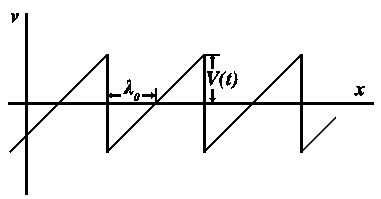
The large-scale density waves witnessed in our simulations develop weak-shock profiles, which are controlled by a competition between nonlinear steepening and wave dispersion. Keplerian shear may also play a role as it ‘winds up’ the spiral and decreases the radial wavelength; though by the time this is important most of the wave energy has already dissipated.
A crude model that omits the strong dispersion inherent in our large-scale density waves nevertheless can successfully account for the energy dissipation in the simulations. In such a model the density wave profiles are dominated by steepening and can thus be approximated by a sawtooth shape propagating at the sound speed velocity (see figure 13). The evolution of the amplitude of such isentropic waves is given by Landau & Lifshitz (1959). In the wave frame of reference, the gas velocity at the shock crest evolves over time as the shock wave dissipates:
| (35) |
where is the excitation amplitude of the wave and its wavelength, assumed to be conserved over the wave propagation. The mean mechanical energy embodied in one wave period at time is given by an integral over radius:
| (36) |
where is the wavelength at time . We next compute the mechanical energy radial flux through a unit surface:
| (37) |
where is the difference between the shocked and pre-shocked density. To compute the last equality, we have used the fact that, under the weak shock approximation, the wave evolution is isentropic and thus (Landau & Lifshitz, 1959). The wave energy and its flux are related through the following conservation law:
| (38) |
while the dissipation rate of the wave is expressed using the mechanical energy conversion into heat per unit time:
| (39) |
where is the wave frequency. We used the density fluctuations in our simulations as the difference between the shocked and pre-shocked density to estimate the local wave heating in Eq. (27).
In addition to that estimate, the thermal energy flux divergence can be used, through Eq. (38), as a way to estimate the radial variation of the wave amplitude:
This must equal the energy rate released as thermal heat given by . Combining the last two expression thus provides an expression for the radial decay of the wave amplitude:
| (41) |
The first term is the geometrical term that described the wave dilution as it propagates cylindrically. The second and third terms are specific to waves propagating in stratified media where mean pressure and sound speed are not uniform. Finally, the last term of the right hand side of this equation reflects the wave damping by shocks. In our simulations, all four terms are of comparable importance.
Appendix C Model with an extended radial extent
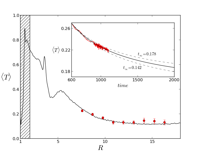
In this section of the appendix we describe the results obtained in the radially extended run. We initiated MHD turbulence in that model in the absence of any dissipative term until the region between and has reached thermal equilibrium (). At that point, we set for . As expected, a dead zone quickly appeared at those radii. Because of the prohibitic computational coast of that simulation (there are cells in the radial direction!), we were not able to run that model until thermal equilibrium is established at all radii. Indeed, the cooling time becomes very long at large radius. Instead, we followed the time evolution of the temperature at nine locations in the dead zone. Due to the absence of turbulent heating, we found that the temperature slowly decreases with time. Assuming this decrease is due to a combination of cooling (resulting from the cooling function) and wave heating, it can be modelled using the following differential equation
| (42) |
where the term accounts for the (unknown) wave heating. We fitted the time evolution of the temperature during the duration of the simulation ( orbits) in order to obtain a numerical estimate of at those nine locations. An example of that fit is provided in the insert of figure 14. Using these value, we can obtain an estimate for the equilibrium temperature in the dead zone, as shown on figure 14. The comparison with the estimate of Eq. (28) provided by the black line is excellent everywhere in the dead zone.
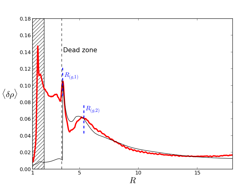
As a sanity check, we test here if the wave amplitude decreases as their energy content is converted into heat. We show on figure 15 the mean density fluctuation profile obtained in the extended simulation. It exhibits two maxima close to the dead zone inner edge located at and and the amplitude decay with radius. The reason why we see two such maxima is not clear but might be due to waves originated at the dead/active interface as well as waves excited as the location of the pressure maximum. In any case, we found that modelling the amplitude of fluctuations as the signature of a combination of two waves generated at gives acceptable results. We use an explicit scheme to numerically integrate Eq.(41) from the wave generation locations . The two waves are excited with the amplitude measured at with the frequency . We plot the solution thus obtained on figure 15. The good agreement between the analytical solution and the profile gives a final confirmation that waves control the dead zone thermodynamics.
Appendix D Simulation with a higher resolution
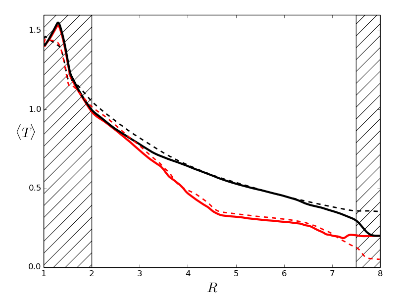
Here we present a brief test of the impact of spatial resolution on our results. We have restarted the run from the thermal equilibrium of the ideal MHD case () and the static dead zone case (), with twice as many cells in each direction. The resolution is . We show the averaged temperature profile of both cases on figure 16. Because of the large computational cost, each models are integrated for orbits and time averages are only performed over the last orbits. The temperature profiles of each case are very close to those obtained with the fiducial runs. We conclude that resolution as little impact on our results.
References
- Armitage (1998) Armitage, P. J. 1998, ApJ, 501, L189
- Balbus (2004) Balbus, S. A. 2004, ApJ, 600, 865
- Balbus (2011) Balbus, S. A. 2011, Magnetohydrodynamics of Protostellar Disks, ed. P. J. V. Garcia, 237–282
- Balbus & Hawley (1998) Balbus, S. A. & Hawley, J. F. 1998, Reviews of Modern Physics, 70, 1
- Balbus & Hawley (2000) Balbus, S. A. & Hawley, J. F. 2000, in From Dust to Terrestrial Planets, 39
- Balbus & Papaloizou (1999) Balbus, S. A. & Papaloizou, J. C. B. 1999, ApJ, 521, 650
- Barge & Sommeria (1995) Barge, P. & Sommeria, J. 1995, A&A, 295, L1
- Baruteau et al. (2011) Baruteau, C., Fromang, S., Nelson, R. P., & Masset, F. 2011, A&A, 533, A84
- Beckwith et al. (2011) Beckwith, K., Armitage, P. J., & Simon, J. B. 2011, MNRAS, 416, 361
- Blaes & Balbus (1994) Blaes, O. M. & Balbus, S. A. 1994, ApJ, 421, 163
- Chambers (2009) Chambers, J. E. 2009, ApJ, 705, 1206
- Charignon & Chièze (2013) Charignon, C. & Chièze, J.-P. 2013, A&A, 550, A105
- Chiang & Goldreich (1997) Chiang, E. I. & Goldreich, P. 1997, ApJ, 490, 368
- D’Alessio et al. (1998) D’Alessio, P., Canto, J., Calvet, N., & Lizano, S. 1998, ApJ, 500, 411
- Dzyurkevich et al. (2010) Dzyurkevich, N., Flock, M., Turner, N. J., Klahr, H., & Henning, T. 2010, A&A, 515, A70
- Flaig et al. (2010) Flaig, M., Kley, W., & Kissmann, R. 2010, MNRAS, 409, 1297
- Fleming & Stone (2003) Fleming, T. & Stone, J. M. 2003, ApJ, 585, 908
- Flock et al. (2013) Flock, M., Fromang, S., González, M., & Commerçon, B. 2013, A&A, 560, A43
- Fromang et al. (2006) Fromang, S., Hennebelle, P., & Teyssier, R. 2006, A&A, 457, 371
- Fromang & Papaloizou (2006) Fromang, S. & Papaloizou, J. 2006, A&A, 452, 751
- Fromang et al. (2007) Fromang, S., Papaloizou, J., Lesur, G., & Heinemann, T. 2007, A&A, 476, 1123
- Hawley (2001) Hawley, J. F. 2001, ApJ, 554, 534
- Hirose et al. (2006) Hirose, S., Krolik, J. H., & Stone, J. M. 2006, ApJ, 640, 901
- Hirose & Turner (2011) Hirose, S. & Turner, N. J. 2011, ApJ, 732, L30
- Igea & Glassgold (1999) Igea, J. & Glassgold, A. E. 1999, ApJ, 518, 848
- Klahr & Bodenheimer (2003) Klahr, H. H. & Bodenheimer, P. 2003, ApJ, 582, 869
- Kretke et al. (2009) Kretke, K. A., Lin, D. N. C., Garaud, P., & Turner, N. J. 2009, ApJ, 690, 407
- Landau & Lifshitz (1959) Landau, L. D. & Lifshitz, E. M. 1959, Fluid mechanics, 385–390
- Latter & Balbus (2012) Latter, H. N. & Balbus, S. 2012, MNRAS, 424, 1977
- Latter et al. (2010) Latter, H. N., Bonart, J. F., & Balbus, S. A. 2010, MNRAS, 405, 1831
- Lesur & Longaretti (2007) Lesur, G. & Longaretti, P.-Y. 2007, MNRAS, 378, 1471
- Lesur & Papaloizou (2010) Lesur, G. & Papaloizou, J. C. B. 2010, A&A, 513, A60
- Lovelace et al. (1999) Lovelace, R. V. E., Li, H., Colgate, S. A., & Nelson, A. F. 1999, ApJ, 513, 805
- Lyra et al. (2009) Lyra, W., Johansen, A., Zsom, A., Klahr, H., & Piskunov, N. 2009, A&A, 497, 869
- Lyra & Mac Low (2012) Lyra, W. & Mac Low, M.-M. 2012, ApJ, 756, 62
- Meheut et al. (2012) Meheut, H., Meliani, Z., Varniere, P., & Benz, W. 2012, A&A, 545, A134
- Nelson & Gressel (2010) Nelson, R. P. & Gressel, O. 2010, MNRAS, 409, 639
- Oishi & Mac Low (2009) Oishi, J. S. & Mac Low, M.-M. 2009, ApJ, 704, 1239
- Perez-Becker & Chiang (2011) Perez-Becker, D. & Chiang, E. 2011, ApJ, 735, 8
- Petersen et al. (2007a) Petersen, M. R., Julien, K., & Stewart, G. R. 2007a, ApJ, 658, 1236
- Petersen et al. (2007b) Petersen, M. R., Stewart, G. R., & Julien, K. 2007b, ApJ, 658, 1252
- Pierens et al. (2012) Pierens, A., Baruteau, C., & Hersant, F. 2012, MNRAS, 427, 1562
- Pneuman & Mitchell (1965) Pneuman, G. W. & Mitchell, T. P. 1965, Icarus, 4, 494
- Raettig et al. (2013) Raettig, N., Lyra, W., & Klahr, H. 2013, ApJ, 765, 115
- Sano et al. (2000) Sano, T., Miyama, S. M., Umebayashi, T., & Nakano, T. 2000, ApJ, 543, 486
- Shakura & Sunyaev (1973) Shakura, N. I. & Sunyaev, R. A. 1973, A&A, 24, 337
- Simon & Hawley (2009) Simon, J. B. & Hawley, J. F. 2009, ApJ, 707, 833
- Sorathia et al. (2012) Sorathia, K. A., Reynolds, C. S., Stone, J. M., & Beckwith, K. 2012, ApJ, 749, 189
- Steinacker & Papaloizou (2002) Steinacker, A. & Papaloizou, J. C. B. 2002, ApJ, 571, 413
- Teyssier (2002) Teyssier, R. 2002, A&A, 385, 337
- Ulmschneider (1970) Ulmschneider, P. 1970, Sol. Phys., 12, 403
- Umebayashi & Nakano (1988) Umebayashi, T. & Nakano, T. 1988, Progress of Theoretical Physics Supplement, 96, 151
- Varnière & Tagger (2006) Varnière, P. & Tagger, M. 2006, A&A, 446, L13
- Zhu et al. (2009a) Zhu, Z., Hartmann, L., & Gammie, C. 2009a, ApJ, 694, 1045
- Zhu et al. (2009b) Zhu, Z., Hartmann, L., Gammie, C., & McKinney, J. C. 2009b, ApJ, 701, 620
- Zhu et al. (2010) Zhu, Z., Hartmann, L., Gammie, C. F., et al. 2010, ApJ, 713, 1134