Strict limit on in-plane ordered magnetic dipole moment in URu2Si2
Abstract
Neutron diffraction is used to examine the polarization of weak static antiferromagnetism in high quality single crystalline URu2Si2. As previously documented, elastic Bragg-like diffraction develops for temperature K at but not at wave vector transfer . The peak width indicates correlation lengths Å and Å. The integrated intensity of the dependent peaks corresponds to a sample averaged -oriented staggered moment of at K. The absence of dependent diffraction at places a limit on an or orbital based in-plane staggered magnetic dipole moment, which is associated with multipolar orders proposed for URu2Si2.
I Introduction
Over two decades of concerted theoretical and experimental effort has so far failed to reveal the true nature of the so-called “hidden order” (HO) in the heavy-fermion material, URu2Si2 mydosh2011colloquium . The enigmatic HO state is signaled by a sharp specific heat anomaly at = 17.5 K palstra1985superconducting ; maple1986partially , but the nature of the underlying order parameter is unresolved. This state of affairs has fueled an active subfield of research, with many creative theoretical proposals, and a full battery of experimental techniques brought to bear on the problem.mydosh2011colloquium The eventual explanation for the HO in centered tetragonal URu2Si2 will need to account for numerous intriguing experimental findings, including strong fermi-surface (FS) reconstruction below THO palstra1985superconducting ; maple1986partially , an antiferromagnetic phase that is reached from the HO phase by applying pressure amitsuka1999 but does not appear to affect the FS,nakashima2003haas ; PhysRevLett.105.216409 -axis polarized spin fluctuations which become gapped and coherent at THO wiebe2007gapped , and most recently, the identification of C4 rotational symmetry breaking of the weak basal-plane spin susceptibility. okazaki2011rotational
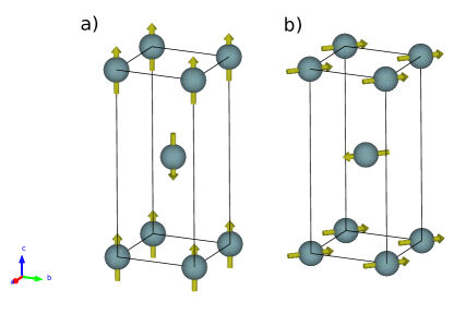
One of the first experimental signals which seemed to correlate with THO was found using elastic neutron scattering. The first neutron studies revealed the onset of the so-called Small Moment Antiferromagnetic (SMAF) phase below THO, which was characterized by a (100) ordering wave vector, and a very small ordered moment of approximately 0.03 .broholm1987magnetic ; mason1990neutron ; isaacs1990 ; broholm1991magnetic The magnetic structure in the SMAF phase consists of dipole moments oriented along the -axis, with ferromagnetically ordered layers alternating anti-ferromagnetically along the -axis (Figure 1 a). The reported size of the ordered moment varies from 0.011 to 0.03 /U in single crystal samples.broholm1987magnetic ; mason1990neutron ; isaacs1990 ; broholm1991magnetic ; Amitsuka2007 It is now clear that lattice strain can induce stronger sample averaged staggered magnetization possibly through inclusions of droplets of the pressure induced large moment phase,luke1994muon ; matsuda2001 ; amato2004weak ; niklowitz2010 and 29Si NMR places an upper limit of 0.0002 on a homogeneous -axis oriented staggered moment that is static on the microsecond time scale (Fig. 1(a)). takagi2007no High quality samples at ambient pressure are generally found to have a 0.01 to 0.02 staggered magnetization, with a correlation length in excess of 200 Å as in the present experiment. Whether intrinsic or extrinsic in origin, the size of the ordered moment in the SMAF phase is insufficient to explain the size of the specific heat anomaly at 17.5 K within the conventional framework for rare earth and actinide magnetism,jensen1991rare and thus the true nature of the order parameter remains elusive.
A recent study of the magnetic susceptibility of small crystals of URu2Si2, using the highly sensitive torque magnetometry technique, has revealed C4 symmetry breaking in the basal plane of the tetragonal unit cell.okazaki2011rotational This symmetry breaking onsets at in small crystals, indicating the formation of domains of the broken symmetry state. Since this discovery, additional experiments have confirmed the presence of C4 symmetry breaking through NMR line width broadening kambe2013nmr and an anisotropic cyclotron resonance signal tonegawa2012cyclotron . Theoretical proposals have been put forth to explain the C4 symmetry breaking, including spin nematic order fujimoto2011spin , a spin-orbit density wave das2013imprints , and a modulated spin liquid phase.pepin2011modulated These proposals show how spin rotation symmetry could be broken while respecting time reversal symmetry, and hence avoiding the formation of a magnetic dipole moment in the basal plane. However, another possibility is also evident: small in-plane ordered dipole moments which have so far escaped detection.
Though a small ordered in-plane dipole moment would not by itself account for the change of entropy at the hidden order transition any more than the -oriented SMAF, its presence or absence is critical to understanding C4 symmetry breaking. A putative transverse staggered magnetization was recently considered in three separate theoretical works. Rau et alrau2012hidden proposed a spin density wave (SDW) involving 5 crystal field doublets. The (undetermined) details of the crystal field wavefunctions dictate the size of the in-plane moment induced by such a SDW, which could be vanishingly small. Nevertheless, a small moment of unspecified magnitude pointing along [110] is expected in this case rau2012hidden . A second theoretical prediction of a small in-plane moment comes from Chandra et al, who propose the order parameter characterizing the HO phase is hybridization between conduction electrons and local Ising-like 5 wavefunctions, the combination of which produce an object that breaks both single and double time-reversal symmetry, a so-called “hastatic” order which entails a small in-plane moment in the hidden order phase. Chandra2013 Chandra et al place a theoretical upper limit of = 0.015 on the size of the in-plane ordered moment. A third paper examines the complete set of multipole correlations allowed in URu2Si2 ikeda2012emergent . Employing density functional theory to establish a multi band Anderson Hamiltonian and augmented RPA theory to account for interactions, a rank-5 multipole (dotriacontapole) order with ‘nematic’ E- symmetry was found to be critical to a low temperature condensed phase. While no estimate of magnitude is provided, a staggered pseudospin moment along the [110] direction is concomitant to this order. Although the dotriacontapole order was initially supported by the interpretation of high magnetic field neutron diffraction data, ressouche2012hidden this conclusion has recently been discounted based on a space group analysis.khalyavin2014symmetry Furthermore, a recent photoemission study of the FS in URu2Si2 meng2013imaging did not observe features associated with dotriacontapole ordering in Ref. ikeda2012emergent, . The photoemission experiment provided evidence for itinerant 5 electrons so that theories relating to (localized) crystal field wave functions such as Refs. rau2012hidden, to Chandra2013, may be called into question. Nevertheless, even in the absence of a fully consistent theory, in light of the C4 symmetry breaking magnetic susceptibility data, it is of utmost importance to establish whether or not a small dipole moment is formed in the basal plane of URu2Si2.
We therefore performed an elastic neutron scattering experiment to search for a small ordered in-plane dipole moment in a single crystal of URu2Si2. Our measurement puts an upper limit on the possible size of any such moment of 0.0011 assuming a magnetic form factor appropriate to the 5 electron configuration of U3+. Because the measurement was carried out as close as possible (=(001)) to the origin of reciprocal space, the limit is relatively insensitive to the electronic orbital associated with a putative staggered magnetization.
II Experimental Method
A large single crystal of URu2Si2 was grown by the Czochralski method using a Tri-Arc furnace at McMaster University. The crystal was oriented in the plane and mounted in a helium flow cryostat on the SPINS triple-axis spectrometer at the NIST Center for Neutron Research. The instrument was configured for elastic scattering with = = 4.7 meV, using a vertically focussed PG(002) monochromator and a flat PG(002) analyzer. The Full Width at Half Maximum energy resolution for this configuration is 0.27 meV. Cooled beryllium filters were used before and after the sample to eliminate second order () contamination. SPINS has a nickel supermirror guide before the monochromator, giving an energy-dependent incident beam divergence of 1 degree Å-1/, where is the incident wavenumber of the neutrons. Soller collimators (80’ before and after the sample) were in place to control the in-plane beam divergence.
The magnetic neutron scattering cross section is sensitive to the relative orientation of the scattering wave-vector, , to the direction of the magnetic moment, . Specifically, the cross section is maximal for and exactly zero for . Thus, for a magnetic structure with moments oriented along the -axis (Fig. 1(a)) there is no magnetic contribution to Bragg scattering at -type positions. In contrast, for in-plane ordered moment, such as that proposed in Refs. rau2012hidden, , ikeda2012emergent, , and Chandra2013, and shown in Fig. 1(b), the polarization factor is largest for -type positions. With our experimental configuration, we can access reflections and differentiate between transverse and in-plane ordered moments by focusing on - and - type reflections, respectively.
The space group for URu2Si2 is centered tetragonal. The conventional tetragonal unit cell, which contains two formula units, has lattice parameters and Å at T=293 K and the general selection rule for reflections with Miller indices in the corresponding tetragonal reciprocal lattice is . The magnetic structures proposed (in-plane moment, Fig. 1 b)) and measured (-axis SMAF phase, Fig. 1 a)), however, break the centering translational symmetry and produce peaks at the nuclear-forbidden positions. This provides an ideal scenario to search for small magnetic signals on a low background at where , while differentiating between in-plane and transverse ordered moments through the polarization factor.
A note on our choice of incident energy is appropriate. The use of cold neutrons with low incident energy allows us to analyze the elastically scattered neutrons with an energy resolution of 0.27 meV, thereby excluding inelastic processes which could contribute to overall background and obscure a small signal. We chose an incident energy of 4.7 meV to avoid the effects of multiple-scattering. Possibilities for multiple-scattering, i.e. where some proportion of the detected neutrons have undergone more than one scattering process before being detected, depend on the incident energy and details of the Bragg reflection geometry. The effect can be strong for large samples such as the one studied here to achieve sensitivity to small moment magnetic ordering. Considering the lattice parameters for URu2Si2 and our use of the scattering plane, we find there are no multiple Bragg scattering processes for the (001) or (003) positions and neutron energies from 3.34 to 4.71 meV (Appendix C).
III Results and Discussion
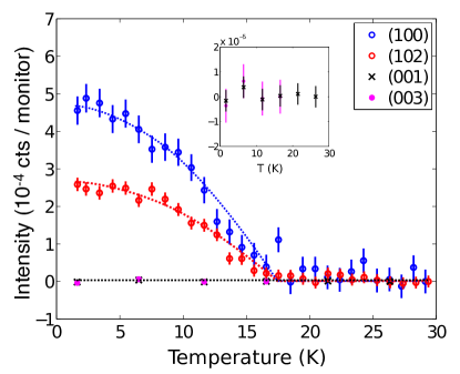
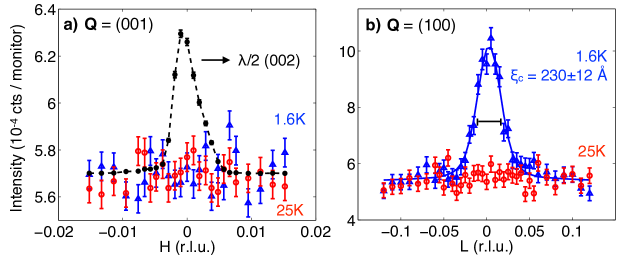
First, we looked for the SMAF ordered moment polarized along the -axis. Figure 2 shows the temperature dependence of the (100) and (102) peak intensities. Both are allowed magnetic Bragg peaks for this type of ordering (Figure 1 a)). The (100) and (102) reflections were collected at 3 minutes and 10 minutes per point, respectively, and the intensity is normalized to a monitor in the incident beam with a count rate of 6100 counts/s. Both reflections show a temperature dependence consistent with a transition near 17.5 K, the hidden order transition temperature. In contrast, the intensities at (001) and (003), which are sensitive to static in-plane order, show no increase above background. For this temperature scan, the intensity at the (001) position was measured for 2.8 hours per point, while (003) was measured for 55 min per point. Transverse scans at (001) and (100) are shown in Figure 3, at two temperatures, 1.6 K and 25 K. The (100) peak disappears above the transition. The (001) position does not show a peak at either temperature. To prove the trajectory probed actually passed through the (001) location in reciprocal space we also show data collected without the beryllium filters in the beam (black filled symbols). Under those conditions there is a component of neutrons that diffracts from the (002) nuclear Bragg peak. It appears exactly where a putative (001) magnetic peak would occur for neutrons. There is no sign of a rod of scattering parallel to at (001) which would manifest as a peak in the transverse scan at both temperatures. The lack of rods is an indication of reduced stacking faults in this crystal, which is consistent with the relatively small SMAF moment (). broholm1987magnetic ; isaacs1990 ; Amitsuka2007 Fig. 3(b) shows transverse scans through the (100) position. From a flat background in the PM phase (T=25 K) a peak develops in the HO phase (T=1.6 K). This peak is not resolution limited (horizontal bar and Fig. 5(a)-(b)). A fit of perpendicular scans through (100) to a Lorentzian convoluted by a Gaussian leads to correlation lengths of =230(12) Å and =240(15) Å along the and directions respectively. Previously reported correlation lengths for URu2Si2 range from 200 Åisaacs1990 to 400 Åbroholm1987magnetic for the -axis and 100 Åbroholm1991magnetic to 450 Åisaacs1990 for the -axis.
To determine the size of the out-of-plane magnetic moment and place limits on the in-plane moment , we normalize to the (101) nuclear reflection, which has the weakest structure factor of any reflection from the URu2Si2 crystal structure, and therefore is least affected by extinction. Details of the normalization are given in Appendix A.
Entering into the magnetic cross section is the magnetic form factor, , which is the Fourier transform of the unpaired spin density and depends on the spatial distribution of spin density. In the “hastatic order” scenario, contains both conduction electron and 5 components, and presumably has a more extended spin density. Figure 4 shows the magnetic form factor for various spin density distributions. Two possibilities for a localized U moment are shown, namely the 5 and 5 electronic configuration along with some other possibilities that relate to moments forming from bands derived from Ru or Si orbitals. We also reproduce the measured magnetic form factor squared from itinerant magnetic excitations associated with Ru in Sr2RuO4 servant2002magnetic . For Si, we show the square of the normalized x-ray atomic scattering factor, tabulated in Ref. brown2006magnetic, , which measures the Fourier transform of the total local electron density. These latter approximations are only intended to show plausible variations in magnetic form factor around the (001) and (003) positions, and not to represent realistic calculations for spin density in URu2Si2. We note that because we are basing the size of the upper limit for solely on a measurement at the (001) position, which has a very small wave-vector ( = 0.65 Å-1), sensitivity to the choice of form factor is small, approximately 1 %. Upper limits that are based on the (003) position with = 1.95 Å-1 are affected much more severely. Thus, though our limit is consistent with that quoted by Das et al,das2013absence and is stricter than that quoted by Metoki et al, metoki2013neutron those experiments are essentially only sensitive to local 5 electron magnetism, since they are based in partdas2013absence or entirelymetoki2013neutron on data from (003).
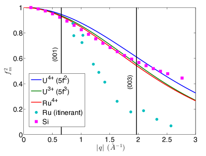
Table 1 summarizes the measured intensities of the relevant magnetic and nuclear peaks, as well as the derived magnetic moments. We use form factors based on the U 5 and 5 electronic configurations to determine and , respectively (5 was chosen for since it produces a more relaxed limit).
| Reflection | T (K) | (barns) | (barns) | () |
|---|---|---|---|---|
| (101) | 26 | 0.29(6) | 0.29 | – |
| (100) | 1.6 | 10.0(8) | – | 0.022(1) |
| (102) | 1.6 | 6.7(5) | – | 0.022(1) |
| (001) | 1.6 | 3.0(2) | – | 0.0011 |
IV Conclusions
Our search for an in-plane ordered dipole moment in a high quality single crystal of URu2Si2 places an upper limit of on the size of any such moment with a correlation length in excess of 200 Å. Our measurement cannot rule out ordered in-plane moments smaller than this or with a substantially shorter correlation length. We note that it is still within the bounds placed on the dipole moment produced in an ordered dotriacontapole model.ikeda2012emergent The assumption of a localized 5 character of the magnetic form factor may not be suitable for theories such as the hastatic order, where the in-plane moment arises in part from conduction electrons with a more extended spin density distribution. In that case, the size of the magnetic moment consistent with our measurements (and others obtained from neutron scattering das2013absence ; metoki2013neutron ) could be larger than the value quoted here. With a specific form factor it would be possible to calculate a new limit based on the magnetic scattering structure factor listed in Table 1.
Our experiment thus places strict and well-defined constraints on theories with in-plane magnetic dipole moments, such as the theories of hastatic order Chandra2013 and rank-5 superspin density waverau2012hidden . This may shift the focus to theories where C4 rotational symmetry is broken while retaining time-reversal symmetry.
The authors acknowledge illuminating discussions with P. Chandra, P. Coleman and R. Flint. K.A.R. acknowledges the helpful logistical assistance of J.W. Lynn. Work at IQM was supported by the US Department of Energy, office of Basic Energy Sciences, Division of Material Sciences and Engineering under grant DE-FG02-08ER46544. This work utilized facilities supported in part by the National Science Foundation under Agreement No. DMR-0944772.
Appendix A Normalized Neutron Diffraction
The elastic magnetic neutron scattering cross section at a reciprocal lattice vector associated with a periodic magnetic structure is, squires2012introduction
| (1) |
where is the magnetic dipole moment of the neutron in units of the nuclear Bohr magneton, cm is the classical electron radius, and is the magnetic structure factor, which, for collinear moments, is given by
| (2) |
where is the Landé g-factor, is the expectation value of the angular momentum operator, is the magnetic form factor (Eqn. 12), is the Debye-Waller factor, which accounts for atomic thermal motion and which is indistinguishable from unity at temperatures and wave vectors of interest, , and the sum is over the atom basis. In the case of URu2Si2, the basis consists of two ions at and . The magnetic structure factor reduces to,
For the SMAF structure , producing non-zero intensity at (100), (300) etc. For the proposed in-plane moments, , and intensity should arise at (001), (003), etc. Details of the magnetic form factors, , are given in Appendix B.
| Refl. | c | moment | |||
| (Å-1) | ( counts/monitor) | direction | |||
| (100) | 1.5217 | 2.8(1)a | 0.0215(8) | 0.0222(9) | |
| (102) | 2.0097 | 2.0(1)a | 0.0201(9) | 0.0210(9) | |
| (001) | 0.6563 | 0.0085b | 0.00105(3) | 0.00106(3) | |
| (101) | 1.6572 | 8200(500)a | – | – | – |
is determined using the integrated area of a transverse q-scan across the peak of interest (), via where is the area of a transverse scan through the two-dimensional resolution function (normalization defined in Eqn. 10), plotted in Fig. 5c) as a function of .
is determined from the maximum peak height, , via .
c Moments are listed for two choices for the magnetic form factor, as shown in Fig. 4.
The coherent elastic nuclear scattering cross section is given by,
| (3) |
where is the nuclear structure factor, given by
| (4) |
where is the coherent scattering length for the atom which is located at the basis vector , and is the Debye-Waller factor.
Denote a three-dimensional resolution function for elastic diffraction as with the same normalization condition as the Dirac -function:
| (5) |
The monitor-normalized intensity near a nuclear Bragg peak, , takes the following form:
| (6) |
Here is a suitably dimensioned pre-factor, which absorbs all sensitivity related factors characterizing a given instrumental configuration.
Containing the identical pre-factor, the corresponding expression for magnetic scattering under the same experimental conditions reads
| (7) |
Here we have defined the transverse projection of the magnetic vector structure factor:
| (8) |
If, as for , the chemical structure and therefore the nuclear scattering cross section is well known, the dimensionless squared magnetic structure factor can be determined through ratios of peak intensities as follows:
| (9) |
Note that by using the fact that the resolution perpendicular to the scattering plane is independent of the scattering angle, we have split off that part of the resolution function so as to focus on the two-dimensional in-plane elastic resolution function with the following normalization condition:
| (10) |
The magnetic structure factor can also be obtained from a ratio of integrated intensities
| (11) | |||||
Here it is understood that the path of integration is matched for the measured integrated intensity and the corresponding integral over the resolution function. In Equations 9 and 11 the measured intensity ratio is balanced by the corresponding ratio for the resolution function. If the latter ratio will not deviate significantly from one.
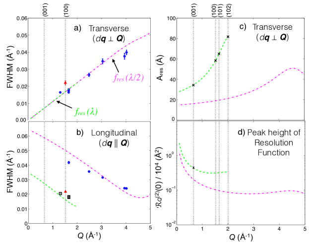
The resolution function can readily be calculated based on the instrumental configuration.cooper1967resolution Fig. 5 shows the wave vector dependence of various aspects of the resolution function. By comparing the experimentally measured width of nuclear Bragg peaks with the calculated widths, Figs. 5(a) and (b) indicate that the calculation based on the known beam divergences and the instrument geometry accurately reflects the instrumentation configuration. Fig. 5(c) shows the wave vector dependence of the transverse (rocking) integral through the resolution function for use in Eq. 11 and Fig. 5(d) depicts the q-dependence of the peak value of the normalized two dimensional elastic resolution function for use in Eq. 9.
Table II shows the values for the -oriented staggered magnetization calculated from the (100) and (102) magnetic peak intensities using Eq. 11.
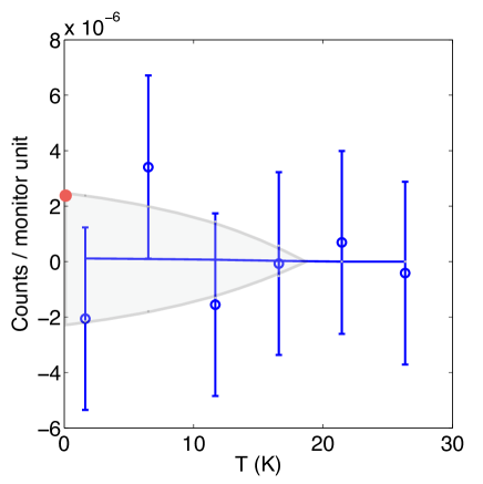
To determine the upper bound on , we fit the intensity vs. temperature data at (001) to the following functional form,
This form represents an order parameter curve, as could be expected for a 2nd order phase transition. We fix (in the absence of further information about the universality class of the transition) and K and allow to vary. The fitted value is , and we take the maximum possible value of consistent with this fit to determine the upper limit on the in plane moment, (Fig. 6), through Eqn. 9. The corresponding limits based on different possible form factors are listed in Table II.
Appendix B Form factor
The electronic configuration associated with magnetism in URu2Si2 is not known. Two possibilities are U4+ () or U3+ (). flint2012 The magnetic form factor, , which enters into Eqn. 1, is slightly different for the two configurations. The form factor, which accounts for the spatial distribution of unpaired spin density in the atomic orbitals, can be approximated by the first two terms in a harmonic expansion,brown2006magnetic
| (12) |
where is the Landé -factor and,
| (13) |
Here is the radial wave function for the unpaired spins and is the spherical Bessel function.
The form factors were calculated at the relevant wave vectors using data from Ref. brown2006magnetic, and are tabulated in Table 2 for both and configurations. We choose the configuration for determining , consistent with Ref. broholm1991magnetic, . For the upper limit on , we choose the form factor for the configuration since it produces a more relaxed upper limit.
Appendix C Multiple Scattering
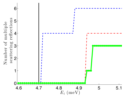
Multiple elastic scattering can occur when a sphere of radius centered at passes through reciprocal lattice points other than the origin and the desired reflection. Figure 7 shows how many such reflections (with distances within 0.05 Å-1) exist for URu2Si2 arranged in the scattering plane, as a function of incident energy. Our chosen incident energy of 4.7 meV is free of multiple scattering (shown by the black line).
References
- (1) J. A. Mydosh and P. M. Oppeneer, Reviews of Modern Physics 83, 1301 (2011).
- (2) T. T. M. Palstra, A. A. Menovsky, J. Van den Berg, A. J. Dirkmaat, P. H. Kes, G. J. Nieuwenhuys, and J. A. Mydosh, Phys. Rev. Lett. (1985).
- (3) M. B. Maple, J. W. Chen, Y. Dalichaouch, T. Kohara, C. Rossel, M. S. Torikachvili, M. W. McElfresh, and J. D. Thompson, Phys. Rev. Lett. 56, 185 (1986).
- (4) H. Amitsuka, M. Sato, N. Metoki, M. Yokoyama, K. Kuwahara, T. Sakakibara, H. Morimoto, S. Kawarazaki, Y. Miyako, and J. A. Mydosh, Phys. Rev. Lett. 83, 5114 (1999).
- (5) M. Nakashima, H. Ohkuni, Y. Inada, R. Settai, Y. Haga, E. Yamamoto, and Y. Onuki, Journal of Physics: Condensed Matter 15, S2011 (2003).
- (6) E. Hassinger, G. Knebel, T. D. Matsuda, D. Aoki, V. Taufour, and J. Flouquet, Phys. Rev. Lett. 105, 216409 (2010).
- (7) C. R. Wiebe, J. A. Janik, G. J. MacDougall, G. M. Luke, J. D. Garrett, H. D. Zhou, Y.-J. Jo, L. Balicas, Y. Qiu, J. R. D. Copley, et al., Nature Physics 3, 96 (2007).
- (8) R. Okazaki, T. Shibauchi, H. J. Shi, Y. Haga, T. D. Matsuda, E. Yamamoto, Y. Onuki, H. Ikeda, and Y. Matsuda, Science 331, 439 (2011).
- (9) J. G. Rau and H.-Y. Kee, Phys. Rev. B 85, 245112 (2012).
- (10) H. Ikeda, M.-T. Suzuki, R. Arita, T. Takimoto, T. Shibauchi, and Y. Matsuda, Nature Physics 8, 528 (2012).
- (11) P. Chandra, P. Coleman, and R. Flint, Nature 493, 621 (2013).
- (12) C. Broholm, J. K. Kjems, W. J. L. Buyers, P. Matthews, T. T. M. Palstra, A. A. Menovsky, and J. A. Mydosh, Phys. Rev. Lett. 58, 1467 (1987).
- (13) T. E. Mason, B. D. Gaulin, J. D. Garrett, Z. Tun, W. J. L. Buyers, and E. D. Isaacs, Phys. Rev. Lett. 65, 3189 (1990).
- (14) E. D. Isaacs, D. B. McWhan, R. N. Kleiman, D. J. Bishop, G. E. Ice, P. Zschack, B. D. Gaulin, T. E. Mason, J. D. Garrett, and W. J. L. Buyers, Phys. Rev. Lett. 65, 3185 (1990).
- (15) C. Broholm, H. Lin, P. T. Matthews, T. E. Mason, W. J. L. Buyers, M. F. Collins, A. A. Menovsky, J. A. Mydosh, and J. K. Kjems, Phys. Rev. B 43, 12809 (1991).
- (16) H. Amitsuka, K. Matsuda, I. Kawasaki, K. Tenya, M. Yokoyama, C. Sekine, N. Tateiwa, T. C. Kobayashi, S. Kawarazaki, and H. Yoshizawa, Journal of Magnetism and Magnetic Materials 310, 214 (2007).
- (17) G. M. Luke, A. Keren, L. P. Le, Y. J. Uemura, W. D. Wu, D. Bonn, L. Taillefer, J. D. Garrett, and Y. Ōnuki, Hyperfine Interactions 85, 397 (1994).
- (18) K. Matsuda, Y. Kohori, T. Kohara, K. Kuwahara, and H. Amitsuka, Phys. Rev. Lett. 87, 087203 (2001).
- (19) A. Amato, M. J. Graf, A. De Visser, H. Amitsuka, D. Andreica, and A. Schenck, Journal of Physics: Condensed Matter 16, S4403 (2004).
- (20) P. G. Niklowitz, C. Pfleiderer, T. Keller, M. Vojta, Y.-K. Huang, and J. A. Mydosh, Phys. Rev. Lett. 104, 106406 (2010).
- (21) S. Takagi, S. Ishihara, S. Saitoh, H.-i. Sasaki, H. Tanida, M. Yokoyama, and H. Amitsuka, Journal of the Physical Society of Japan 76, 033708 (2007).
- (22) J. Jensen and A. R. Mackintosh, Rare earth magnetism (Clarendon Press, Oxford, 1991).
- (23) S. Kambe, Y. Tokunaga, H. Sakai, T. D. Matsuda, Y. Haga, Z. Fisk, and R. E. Walstedt, Phys. Rev. Lett. 110, 246406 (2013).
- (24) S. Tonegawa, K. Hashimoto, K. Ikada, Y.-H. Lin, H. Shishido, Y. Haga, T. Matsuda, E. Yamamoto, Y. Onuki, H. Ikeda, et al., Phys. Rev. Lett. 109, 036401 (2012).
- (25) S. Fujimoto, Phys. Rev. Lett. 106, 196407 (2011).
- (26) T. Das, arXiv preprint arXiv:1308.1992 (2013).
- (27) C. Pépin, M. R. Norman, S. Burdin, and A. Ferraz, Phys. Rev. Lett. 106, 106601 (2011).
- (28) E. Ressouche, R. Ballou, F. Bourdarot, D. Aoki, V. Simonet, M. T. Fernandez-Diaz, A. Stunault, and J. Flouquet, Phys. Rev. Lett. 109, 067202 (2012).
- (29) D. D. Khalyavin, S. W. Lovesey, A. N. Dobrynin, E. Ressouche, R. Ballou, and J. Flouquet, Journal of Physics: Condensed Matter 26, 046003 (2014).
- (30) J.-Q. Meng, P. M. Oppeneer, J. A. Mydosh, P. S. Riseborough, K. Gofryk, J. J. Joyce, E. D. Bauer, Y. Li, and T. Durakiewicz, Phys. Rev. Lett. 111, 127002 (2013).
- (31) F. Servant, B. Fåk, S. Raymond, J. P. Brison, P. Lejay, and J. Flouquet, Phys. Rev. B 65, 184511 (2002).
- (32) P. J. Brown, International Tables for Crystallography C, 554 (2006).
- (33) P. Das, R. Baumbach, K. Huang, M. Maple, Y. Zhao, J. S. Helton, J. Lynn, E. Bauer, and M. Janoschek, New Journal of Physics 15, 053031 (2013).
- (34) N. Metoki, H. Sakai, E. Yamamoto, N. Tateiwa, T. Matsuda, and Y. Haga, Journal of the Physical Society of Japan 82, (2013).
- (35) G. L. Squires, Introduction to the theory of thermal neutron scattering (Cambridge University Press, Cambridge, 2012).
- (36) M. J. Cooper and R. Nathans, Acta Crystallographica 23, 357 (1967).
- (37) R. Flint, P. Chandra, and P. Coleman, Phys. Rev. B 86, 155155 (2012).