Calibration and performance of the STAR Muon Telescope Detector using cosmic rays
Abstract
We report the timing and spatial resolution from the Muon Telescope Detector (MTD) installed in the STAR experiment at RHIC. Cosmic ray muons traversing the STAR detector have an average transverse momentum of 6 GeV/. Due to their very small multiple scattering, these cosmic muons provide an ideal tool to calibrate the detectors and measure their timing and spatial resolution. The values obtained were 100 ps and 1-2 cm, respectively. These values are comparable to those obtained from cosmic-ray bench tests and test beams.
keywords:
Muon Telescope Detector, cosmic ray, timing resolution, and spatial resolutionPACS:
25.75.Cj, 29.40.Cs1 Introduction
Data taken over the last decade have demonstrated that RHIC has created a hot, dense medium with partonic degrees of freedom called the Quark-Gluon Plasma (QGP). One of the physics goals for the next decade is to study the fundamental properties of the QGP such as the temperature, density profile, and color-screening length via electro-magnetic probes such as di-leptons [2, 3, 4, 5, 6, 7, 8, 9, 10]. Muons can be measured more precisely because of their relatively reduced Bremsstrahlung radiation in the detector materials. Such an improved measurement is essential for separating the meson ground state (1S) from its excited states (2S+3S), each of which is predicted to melt at very different temperatures. The Muon Telescope Detector (MTD) in the Solenoidal Tracker at RHIC (STAR) will allow the measurement of the mesons and mesons, over a broad transverse momentum range through di-muon decays to study color screening features, and -e correlations to distinguish heavy flavor correlations from initial lepton pair production [11]. The MTD will thus provide direct information on the temperature and the characteristics of color screening in the QGP created in RHIC collisions.
The MTD is based on the Multi-gap Resistive Plate Chambers (MRPC) technology. A similar technology was used for the recently installed STAR TOF system [12, 13]. Unlike the TOF MRPCs [14], however, the MTD MRPCs are much larger, and have long double-ended read-out strips. The MTD detectors are positioned behind the iron return bars of the STAR magnet, and cover 45% of the full azimuth within a pseudo-rapidity range of 0.5. The construction and installation of the MTD system was begun in 2011 and will be completed in 2014.
Prototype MTD detectors were built and studied from 2007 to 2011. These detectors were tested in the laboratory with cosmic rays, in test beams, and in STAR experiment during RHIC runs. The cosmic-ray and beam tests indicated a timing (100 ps) and the spatial resolution (1 cm) that would be sufficient to achieve the physics goals [15]. The operation of the prototype MTD detectors in STAR in 2007-2008 demonstrated that clean muon identification could be achieved for muon transverse momenta above a few GeV/. The bench and test-beam results, as well as detailed simulations, thus indicated that the MTD would provide important physics information on quarkonia and primordial di-lepton measurements at RHIC [16]. However, during the tests of the MTD prototypes in STAR in 2007-2008, the timing resolution was 200-300 ps, which was much worse than that observed in the previous cosmic-ray and test-beam studies. This poorer resolution resulted from the particular digitization electronics [17] that were used at that time and the long cables between the MTD detectors and the digitizers.
In 2009, new prototype MTD detectors were installed in STAR. For these prototypes, the simple on-board front-end electronics used previously [18] to drive long cables to the digitizers were replaced with the same electronics as are used in the STAR TOF system [13, 19]. The TOF electronics are based on the CERN HPTDC [20] chip. In 2010, a cosmic-ray trigger based on the information from the MTD prototypes was implemented in the STAR trigger system. High energy (6 GeV) cosmic rays provide an excellent means to study the timing and spatial resolution as the smearing from multiple scattering in the detector materials is a relatively small effect.
In this paper, the timing and spatial resolution of the MTD MRPCs read-out by STAR TOF electronics for cosmic muons reconstructed in the STAR experiment in 2010-2011 will be reported. The performance observed during the operation of 10% of the full MTD system during the 2012 RHIC run will also be presented. This paper is arranged as follows. Section 2 describes the MTD MRPCs, and Section 3 describes the experimental aspects. The details of the data analysis and the MRPC performance are reported in Section 4. The summary and conclusions are then presented in Section 5.
2 MTD MRPC Modules
A number of different MRPC designs were studied for possible use in the MTD system. These include single- and double-stack MRPCs with five or six gas gaps and several different read-out pad geometries. During the 2007-2011 RHIC runs, some of these prototype MRPCs were installed in STAR near mid-rapidity and at a radius of 400 cm. These prototypes were integrated into the STAR data acquisition and trigger systems and took data throughout an entire RHIC run. Events useful for the study of the performance of these detectors were saved using a trigger that required a hit in at least one read-out strip.
| Conditions | Type | trays |
|---|---|---|
| cosmic and test-beam | type A | – |
| Run 7: Au+Au | type A | 2 modules in 1 tray |
| Run 8: d+Au, p+p | ||
| Run 9: p+p | type A | 3 modules in 1 tray |
| Run 10: Au+Au, cosmic trigger | ||
| Run 11: Au+Au, cosmic trigger | type A | 3 A modules in 1 tray |
| type B | 1 B module in 1 tray | |
| type C | 2 C modules in 2 trays | |
| Run 12: p+p, cosmic trigger | type B | 12 modules in 12 trays |
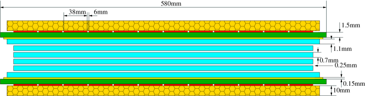
Table 1 summarizes the details of the MRPC modules studied in the 2007-2012 RHIC runs. The MRPC modules were held in gas-tight aluminum boxes called “trays.” A type A MRPC was a double-stack module with 10 gas gaps and 6 readout strips with outer dimensions of 8717 cm2. The read-out pads were double-ended and 2.5 cm wide with 0.4 cm gaps in between each pad. Type B (C) was a single-stack module with 5 (6) 250 m-wide gas gaps and 12 readout strips, also read out on both ends. The module size was 8752 cm2, and the readout pads were 3.8 cm wide with 0.6 cm gaps. For the 2011 RHIC run, one MRPC of type B and two MRPCs of type C were installed in STAR. The type B MRPC, shown schematically in Fig. 1, was selected as the final design for the full MTD system. Twelve of these final-design modules were installed and operated during RHIC Run 12.
The gas mixture used was 95% Freon R-134a and 5% isobutane. The readout electronics were very similar to those implemented in the STAR TOF system. These record the absolute time of particle hits with respect to a master 40 MHz clock with a time conversion for the least significant bit of 24.4 ps. The electronics also provide analog multiplicity information from each end of each MRPC module (as an “or” of all of the strips in that module) to the STAR Level-0 trigger. This information is used both for selecting events with MTD hits, but also to enable triggers based only on prompt hits, which will suppress the MTD backgrounds resulting from hadronic showers in the magnet backlegs. Additional details on the electronics are available in Refs. [13, 19].
3 Experimental Setup
3.1 The STAR Detector
The primary charged-particle tracking device in the STAR experiment [21] is the Time Projection Chamber (TPC) [22]. The TPC is 4 meters long along the beam line and covers the full azimuth and a pseudo-rapidity range of 1. Ionization electrons drift toward the nearest end, where the signals are read out. The TPC is divided into 24 super-sectors, 12 at each end, and each with 45 rows of read-out pads along the radius. Each super-sector is divided into inner and outer sectors. The TPC provides the positions of primary ionization clusters generated by the passage of charged particles. The charged-particle tracks traversing the TPC will curve in the 0.5 T STAR magnetic field with a curvature that depends on the transverse momentum of the track. The ionization energy loss () measured as the areas of these charge clusters can be used for particle identification [23, 24, 25].
The STAR TOF detector [13] was fully installed before the 2010 RHIC run. It covers the full azimuth and pseudo-rapidities 0.9 at a radius of 220 cm. It extends STAR’s particle identification capabilities to momenta of 3 GeV/ for and [26]. The Barrel Electromagnetic Calorimeter (BEMC) is installed outside the TOF system [27]. The TPC, TOF, and BEMC systems are centered in a solenoidal magnetic field generated by the STAR magnet. This magnet is cylindrical and consists of 30 flux-return bars, four end rings, and two pole tips. The return flux path for the field is provided by the outer magnet steel [28]. The 6.85 m long flux-return bars, also called “backlegs,” are trapezoidal in cross-section and 57 cm thick at a radius of 363 cm. These return bars and the BEMC serve as a hadron absorber allowing only muons to reach the MTD in elementary and heavy-ion collisions. Outside these return bars, there are the boxes which contain the photomultiplier tubes (PMT) and electronics for the BEMC. The MTD detectors are mounted to the BEMC PMT boxes at a radius of 400 cm.
3.2 STAR Cosmic Ray Trigger
The simulation of a central AuAu collisions using a realistic description of the STAR geometry demonstrated that most charged hadrons are stopped within the BEMC and backlegs and the few escaping particles (primary or secondary) primarily pass through the gaps between the backlegs [16]. In the experimental data collected during a RHIC run, the average transverse momentum, , of muons reaching the MTD detectors is 2 GeV/. The multiple scattering for 2 GeV/ muons in the backlegs leads to an MTD spatial resolution of 10 cm and a timing resolution of 100 ps. Multiple scattering thus makes it difficult to measure the timing and spatial resolution of the MTD MRPCs. Furthermore, with such a large smearing of the particle paths due to multiple scattering, the random matching between charged particles reconstructed in the TPC and MTD hits leads to significant backgrounds for identifying muons.
In the 2010 RHIC run, a cosmic-ray trigger based on the MTD detectors was implemented. The desired cosmic ray muons traverse the MTD, return bars, BEMC, TOF, and TPC detectors, generating long tracks in the TPC and two hits in the MTD and TOF barrels. As there was only a small patch of MTD detectors, and the TOF was fully installed, the cosmic-ray trigger requires a coincidence of one MTD hit and two TOF hits. Hits belonging to a single muon traversing the TPC are collected and reconstructed into tracks with well-defined trajectory, momentum , and TPC ionization energy loss . The STAR track reconstruction software assumes that particles originate in the center of STAR. Thus, a single cosmic muon passing through all of STAR is reconstructed as two TPC tracks.
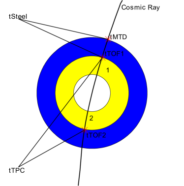
Figure 2 provides a schematic view of a cosmic-ray event in the STAR detector. The time measured by the two TOF detectors and the MTD is called tTOF1, tTOF2, and tMTD, respectively. The calculated time of flight between the two TOF detectors, using the path length and measured by the TPC, is called tTPC. The time of flight from the MTD to the first TOF detector is called tSteel, which can be derived from the track’s helix parameters, momentum , and the 0.5 T magnetic field.
4 Performance of the MTD
4.1 Muon Identification
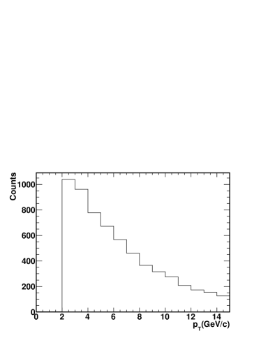
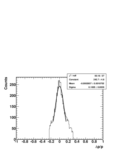
Cosmic ray muon tracks with 2 GeV/ which matched to TOF and MTD hits were selected. The two tracks from one cosmic ray muon were each required to have at least 25 TPC hits (out of the possible 45). The left frame of Fig. 3 shows the distribution of the cosmic-ray muons with 2 GeV/, and the right frame shows the relative momentum difference () distribution of the two TPC-reconstructed tracks from one cosmic-ray muon. The average is about 6 GeV/c and the average momentum resolution is about 10%.
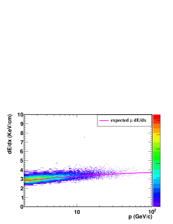
The absolute value of the relative momentum of the two TPC-reconstructed tracks, , was required to be less than 27%. The TPC ionization energy loss, , versus the momentum, , is shown in Fig. 4. The expected muon versus from the Bichsel function is shown as the line in this figure [24]. It describes the data nicely, which demonstrates that a clean sample of cosmic muons was obtained.
4.2 Spatial Resolution
Tracks reconstructed in the STAR TPC were extrapolated to the MTD radius, which allows the measurement of the spatial resolution of the MTD detectors in the direction (along the strips) and the azimuth, , direction (perpendicular to the strips). This extrapolation assumes a magnetic field strength and direction that depends on the radius. The magnetic field is 0.5 T in one direction for radii including the TPC, TOF, and BEMC detectors, and is in the opposite direction with a value of -1.26 T inside the backleg steel. The BEMC PMT boxes and MTD detectors are in a field-free region.
Figure 5 shows the difference between the TPC track extrapolation and the MTD hit position in the direction, , (left frame) and in the direction, , (right frame). For each MTD hit, the hit position in the direction is set at the middle of the strip with biggest signal, and the hit position in the direction can be derived from the signal leading time difference between two readouts of the strip. The MTD detector spatial resolution in the two directions are obtained as the standard deviations of these difference distributions, and are 2.6 cm and 0.006 radians, respectively.
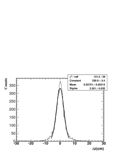

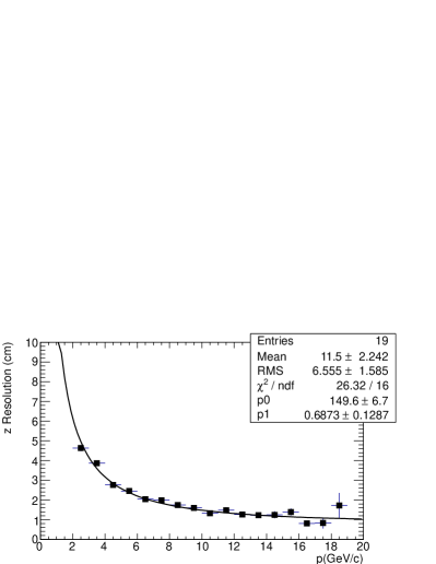
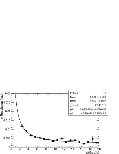
Figure 6 shows the dependence of the spatial resolution along the (left frame) and (right frame) direction as a function of the muon momentum. These data were fit with a functional form motivated by the expectation for the contribution to the measured resolutions from multiple scattering in the detector materials. The formula used was , where and are fit parameters and is the momentum. The spatial resolution of the MTD in the absence of multiple scattering in the detector materials is then given by . According to Fig. 6, the MTD detector spatial resolutions are then 0.8 cm and 2.210-3 rad in the and directions, respectively. The 2.210-3 rad resolution is equivalent to a 0.9 cm resolution of the track at the 400 cm radius of the MTD detectors.
4.3 Time Resolution
The measurement of the time resolution of the MTD detectors is now described. Well-matched tracks were selected by requiring that Z6 cm and 0.2 rad.
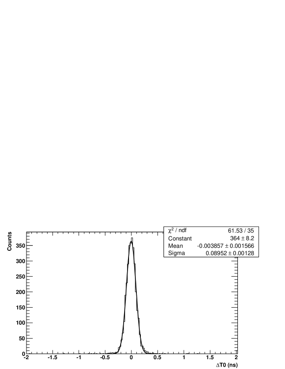
Two times for each muon track, called tTOF1 and tTOF2 (cf. Fig. 2), were provided by the TOF detectors and are used to calculate the “start time” for the event. The resolution of the start time is obtained from the distribution of the time difference, T0 (tTOF2tTOF1)tTPC. Here, (tTOF2tTOF1) is the TOF-measured time-of-flight, and tTPC is the time-of-flight that would be expected for a muon with the trajectory and momentum as reconstructed in the TPC. Figure 7 shows the T0 distribution, from which a standard deviation of 90 ps is observed. The TOF single-detector time resolution is thus 90 ps/, or 64 ps.
To perform the slewing calibration and evaluate the time resolution, the quantity of interest is the MTD time, tMTD, minus the start time from the TOF detectors and the expected time-of-flight for the cosmic muons between the TOF and MTD detectors, tSteel. This is expressed as T (tTOF2tTPCtTOF1)/2 tMTD tSteel (cf. Fig. 2). The T distributions are recorded for each MTD read-out strip separately.
The slewing calibration is done by three passes through the data. To illustrate the procedure, the 2010 data with three type A modules will be used. In both the TOF and MTD systems, the pulse-size metric used for the slewing correction is the pulse width at the leading-edge threshold, which is called “Time over Threshold” (ToT).
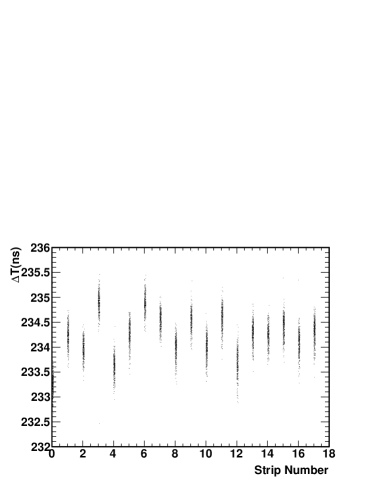
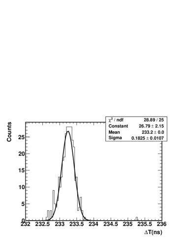
The first step is the extraction of the relative offsets, which proceeds by fitting the T distribution for each strip by a Gaussian, and recording the mean values of these Gaussians. The left frame of Fig. 8 shows the T distribution versus the readout strip, and the right frame shows the T distribution for one strip and the Gaussian fit.
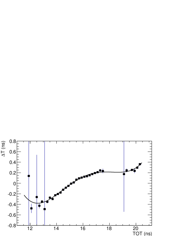
The second step to combine all channels using the relative offsets and plot the slewing itself, which is T versus ToT. The quantity ToT is the geometric mean of the ToT values from the two ends of the lit strip, i.e, . This is fit with a 5th-order polynomial, and an example is shown in Fig. 9. The third step is re-equalize the channel-dependent time offsets after applying the first step’s crude offsets and subtracting the slewing using the 5th-order polynomial.
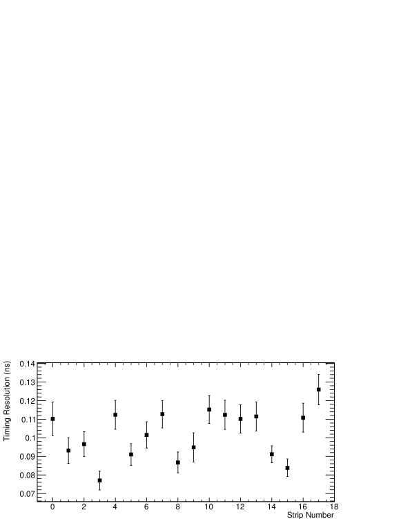
The time resolution is then as the standard deviation of a Gaussian fit to the resulting T distribution, which is shown for each strip in the top frame of Fig. 10. Combining all of the strips and fitting that T distribution with a Gaussian, which is shown in the bottom frame, implies a total time resolution of 104 ps. This resolution includes the start timing resolution of 90ps/2 45 ps and the contribution to the resolution from the multiple scattering for 6 GeV/ muons, which is 25 ps.
After subtracting these two contributions in quadrature, the MTD time resolution is observed to be 90 ps. This is close to the value obtained in the early test beam studies and the bench tests with cosmic rays. The other data sets shown in Tab. 1 were calibrated using the same procedure and the time and spatial position resolution results are summarized in Tab. 2. The performance of the same type of MRPC detector in different years is consistent.
| Conditions | Type | resolution |
|---|---|---|
| cosmic & test-beams [15] | type A | 60 ps, 0.6 cm |
| Run 7: Au+Au [16] | type A | 200-300 ps |
| Run 8: d+Au, p+p | ||
| Run 9: p+p | type A | 90 ps, 0.8 cm (), 0.9 cm () |
| Run 10: Au+Au, cosmic trigger | ||
| Run 11: Au+Au, cosmic trigger | type A | 89 ps, 1.1 cm (), 1.1 cm () |
| type B | 101 ps, 1.4 cm (), 1.6 cm () | |
| type C | 127 ps, 2.4 cm (), 1.8 cm () | |
| Run 12: p+p, cosmic trigger | type B | 108 ps, 2.6 cm (), 1.9 cm () |

5 Conclusions
The time and spatial resolution of the STAR MTD system were obtained using cosmic-ray muons traversing the STAR detector. The relatively high momentum muons can be cleanly triggered upon and selected in the data, and allow studies of the time and spatial resolutions with relatively small contributions from multiple scattering in the STAR detector materials. The MTD resolution values observed in data sets spanning several years were 100 ps for the timing resolution and 1-2 cm for the spatial resolution.
6 Acknowledgments
We thank the STAR Collaboration and the RACF at BNL for their support.
References
- [1]
- [2] J. Adams et al., Nucl. Phys. A 757, 102 (2005).
- [3] I.Arsene et al., Nucl. Phys. A 757, 1 (2005); K. Adcox et al., Nucl. Phys. A 757, 184 (2005); B.B. Back et al., Nucl. Phys. A 757, 28 (2005).
- [4] R. Rapp and J. Wambach, Adv. Nucl. Phys. 25 (2000) 1.
- [5] Electromagnetic Probes at RHIC II (Working Group Report), G. David, R. Rapp and Z. Xu, Phys. Rept. 462, 176 (2008).
- [6] B.I. Abelev et al., Phys. Rev. C 80, 041902 (2009), arXiv:0904.0439.
- [7] H. Satz, J. Phys. G 32, R25 (2006).
- [8] A. D. Frawley, T. Ullrich and R. Vogt, Phys. Rept. 462, 125 (2008).
- [9] T. Matsui and H. Satz, Phys. Lett. B178, 416 (1986).
- [10] A. Mocsy and P. Petreczky, Phys. Rev. Lett. 99, 211602 (2007); Y. Burnier, M. Laine and M. Vepsalainen, JHEP 0801, 043 (2008).
-
[11]
STAR Muon Telescope Detector Proposal:
http://www.star.bnl.gov/ruanlj/MTDreview2010/MTDproposalv14.pdf. -
[12]
STAR Time-of-Flight Proposal:
http://www.star.bnl.gov/STAR/tof/publications/TOF20040524.pdf. - [13] W.J. Llope et al., Nucl. Instr. Meth. A 661, S110 (2012).
- [14] B. Bonner et al., Nucl. Instr. Meth. A 508, 181 (2003); M. Shao et al., Nucl. Instr. Meth. A 492, 344 (2002); J. Wu et al., Nucl. Instr. Meth. A 538, 243 (2005).
- [15] Y. Sun et al., Nucl. Instr. Meth. A 593, 307 (2008); Y. Wang et al., Nucl. Instr. Meth. A 640, 85 (2011).
- [16] L. Ruan et al., J. Phys. G 36, 095001 (2009); Z. Xu, BNL LDRD project 07-007; Beam Test Experiment (T963) at FermiLab.
- [17] F. S. Bieser et al., Nucl. Instr. Meth. A 499, 766 (2003).
- [18] W.J. Llope et al., Nucl. Instr. Meth. A 596, 430 (2008).
- [19] J.J. Schambach et al., Int. J. Mod. Phys. E 16, 2496 (2007).
-
[20]
High Performance Time to Digital Converter Manual:
http://tdc.web.cern.ch/tdc/hptdc/docs/hptdcmanualver2.2.pdf. - [21] K. H. Ackermann et al., Nucl. Instr. Meth. A 499, 624 (2003).
- [22] M. Anderson et al., Nucl. Instr. Meth. A 499, 659 (2003).
- [23] M. Shao et al., Nucl. Instr. Meth. A 558, 419 (2006).
- [24] H. Bichsel, Nucl. Instr. Meth. A 562, 154 (2006).
- [25] Y. Xu et al., Nucl. Instr. Meth. A 614, 28 (2010).
- [26] J. Adams et al., Phys. Lett. B 616, 8 (2005).
- [27] M. Beddo et al., Nucl. Instr. Meth. A 499, 725 (2003).
- [28] F. Bergsma et al., Nucl. Instr. Meth. A 499, 633 (2003).