Optical properties of multilayer optics
including negative index materials
Abstract
Negative indices are revisited through the thin-film admittance formalism. Effective indices and phase delay associated with wave propagation through negative index layers are carefully defined and computational rules easily implementable in standard thin-film software are derived from this approach. This admittance formalism is then used to recover the main features of the perfect lens and to highlight the benefit of such negative index materials to improve the performances of quarter-wavelength Bragg mirrors and Fabry-Perot band-pass filters.
I Introduction
In the field of electromagnetic optics, the past fifteen years have seen the emergence of new and astounding concepts directly connected with the potential availability of artificial materials, such as nano-engineered materials Shalaev_2007 ; Jiang_2013 or photonic crystals Gralak_2000 ; Notomi_2000 . These metamaterials are rationally designed to exhibit unprecedented optical properties like negative Veselago_1968 ; Shelby_2001 or zero Kocaman_2011 index of refraction, which create ways to achieve innovative functionalities unattainable with natural materials, as the perfect flat lens Pendry_2000 or the invisibility cloak Pendry_2006 ; Zolla_2007 ; Schurig_2006 ; Ergin_2010 .
Beside the first preliminary experimental demonstrations of these new and exciting concepts, the thin-film community was used to play with tailored ”arbitrary indices in the complex plane” and to build complex optical functions based on their use: the implementation of the admittance formalism Macleod_2010 was the main mathematical tool to allow for such tailoring. However, despite this favorable context, negative indices have not really been disseminated within this community.
The main objective of this work is to help rectify this situation, by adapting the concept of negative index to the admittance theory, and then by using this extended formalism to analyze the optical properties of some standard multilayer stacks, like the quarter-wavelength Bragg mirror, the Fabry-Perot bandpass filter, or the antireflection coating, where one or more layers of these stacks involve Negative Index Materials (NIMs).
II Negative index of refraction
In general, the refractive index of a medium at a frequency is given from Maxwell’s equations by the following relation
| (1) |
where and are the Fourier transforms of the temporal electric permittivity and magnetic permeability of the medium, and , are the electromagnetic properties of vacuum. Equation (1) is valid for linear and isotropic media, and the Fourier transform involves an exponential in the form .
These frequency dependent quantities are complex, hence the refractive index is not a well-defined single-valued function. Therefore, the computation of the square root of requires the choice of a branch (also called a Riemann sheet Ramakrishna_2005 ), that is a portion of its range over which this function is single-valued. For the square root function, the two possible principal values differ only by their signs. Although the choice of this sign for the refractive index of left-handed metamaterials has been a subject of controversy Chen_2005 ; *Mackay_2006; *Ramakrishna_2007; *Chen_2007; Stockman_2007 ; *Mackay_2007; Govyadinov_2007 , all the proposed approaches provide identical conclusions for media that are both negatively refracting and nonamplifying. As shown in next paragraphs, the choice of the negative sign leads to conditions (on the permittivity and permeability) derived from Maxwell’s equation’s and causality. A first set of relations is
| (2) | |||
| (3) |
where prime and double prime denote the real and imaginary parts of each complex quantity, respectively. The relation (2) is simply the dissipative requirement corresponding to an absorbing or transparent medium. As to the relation (3), it plays a vital role since, as shown hereafter, it ensures that a plane wave decays in amplitude as it propagates in a dissipative NIM medium. Finally, in the low-loss regime, the combination of these relations yields the well-known conditions
| (4) |
In order to understand the link between these last two relations and the wave amplitude decay in a NIM medium, we first compute the square roots of a complex number () by using the following general formula Cooke_2008
| (5) |
where corresponds to the sign of the imaginary part . Then, by introducing the real and imaginary parts of each quantity in equation (1), we infer
| (6) |
and thus, for the refractive index
| (7) |
where is given by
| (8) |
For a plane wave propagating in the positive direction in a NIM medium, the phase and amplitude changes are driven by an exponential in the form
| (9) |
where is the modulus of the wave-vector in vacuum.
Thus, for a NIM medium (), we must choose the minus sign in the general square root formula (5), while the decay of the wave amplitude during the propagation imposes that the condition that be positive or equal to zero, which leads to
Moreover, in the low-loss regime, we can write, as a first approximation
| (10) |
If the product was negative, would be negative too, following (2) and (6), and would be equal to zero, in accordance with (7) taken at the same level of approximation. This means that the product must be positive: The two real parts and are thus of the same sign, and from conditions (2) and (3), we can conclude that they are simultaneously negative, see (4), whereas the refractive index is given, in the same low-loss regime, by Ramakrishna_2005_2
| (11) |
III Admittance formalism
III.1 General presentation
Let us now consider a multilayer stack deposited at the surface of a plane substrate and illuminated by a monochromatic plane wave at an angle of incidence (AOI) . At any position within the stack, the tangential component of the magnetic field and the cross product between the normal to the substrate and the tangential component of the electric field are parallel Macleod_2010 ; Amra_1993 . The algebraic ratio of these quantities is called the complex admittance . Hence
| (12) |
If we are able to compute the complex admittance of the entire stack, we can easily determine the amplitude reflection coefficient of the plane wave on the stack by using the formula
| (13) |
where is the effective index of the incident medium, i.e. the proportionality factor between the same vectors as previously stated, but for the incoming plane wave.
The computation of the factor is based on the application of a recursive formula linking the admittances at two consecutive boundaries Amra_1993
| (14) |
where is the layer number, its effective index and the phase delay introduced by the crossing of this layer. The initialization of this recursive formula is made in the substrate where only the outgoing plane wave is present
| (15) |
where is the total number of layers in the stack and the effective index of the substrate.
Therefore, to define the optical properties of a multilayer stack including a negative index material, we first need to determine the effective index of this artificial material, and then the phase delay associated with the crossing of a layer thickness .
III.2 NIM effective indices
If we first consider the propagation of a plane wave within a transparent positive index material (PIM), we have
| (18) |
and then
| (19) |
For a plane wave passing through a multilayer stack, is an invariant while depends on the layer medium. Therefore, the effective indices of a PIM medium are defined by
| (20) |
where is the vacuum impedance.
For a negative index material illuminated by a plane wave at an angle of incidence , relation (17) becomes
| (21) |
where is the refractive index of the incident medium. To compute , we again need to obtain the square root of a complex number whose real and imaginary parts in this case are defined by
| (22) |
To apply here an approach strictly identical to the one detailed in Section II for a NIM medium in the low-loss regime, we need to satisfy an additional condition
| (23) |
which allows us to give an approximate expression for , i.e.
| (24) |
Moreover, in the transparency regime (), relation (23) can be rewritten as a propagating condition
| (25) |
and the effective indices of the NIM medium are thus given by
| (26) |
The effective indices of a transparent NIM layer (, ) are then positive in the propagating mode.
Besides from that, by using the invariance of , we can replace in (26) by to obtain
| (27) |
The relations defining the effective indices of a NIM layer are thus seen to be identical to those obtained for the effective indices of a PIM layer.
III.3 NIM phase delay
Making use of the results from the previous section, we can easily compute a general expression for the phase delay associated with a NIM layer thickness in the propagating mode of the transparency regime
| (28) |
Using the same approach as in Section III.2 (replacement of by ), we can rewrite relation (28) in the form
| (29) |
III.4 PIM Mirror Image
Let us consider a transparent NIM layer and a standard positive index material (PIM) whose electromagnetic properties (relative electric permittivity and relative magnetic permeability) are equal and opposite to the NIM ones
| (30) |
In the propagating mode of the transparency regime, one can write
| (31) |
This last equation shows that we can simulate the properties of a NIM layer by replacing it with an equivalent PIM layer, provided that we use for this PIM layer a virtual thickness opposite to that of the NIM layer (). We now call this layer the correlated PIM Mirror Image (PIMMI) of the NIM layer.
This property is essential because it allows us to use standard thin-film software to predict, in the propagating mode, the optical properties of interference coatings including one or more NIM layers.
IV The Perfect Lens
Before we can systematically investigate the reflection and transmission of a plane wave by multilayer thin films containing both positively and negatively refracting materials, we start by analyzing the specific case of the Perfect Lens Pendry_2000 with the help of the admittance formalism detailed in the previous section.
A perfect lens can be described as a slab (in other words a single layer) of -1 index material with and surrounded by air (, ). At any AOI , we have
| (32) |
and then following (14)
| (33) |
regardless of the slab thickness . This implies that the reflection coefficient is equal to zero at any angle of incidence and state of polarization (SOP), while the law of conservation of the spatial pulsation takes the form
| (34) |
which imposes : and .
Thanks to the admittance formalism, we also recover very easily two of the three fundamental properties of the Perfect Lens, i.e. its antireflection behavior and its imaging ability. Details of the third fundamental property (evanescent wave amplification Pendry_2000 ) are not required to understand the optical properties of multilayer optics in the propagating mode; thus they are not discussed here.
V Optical properties of NIM/PIM stacks
In this work, we consider ideal negative index materials, i.e. without absorption and spectral dispersion, and above all, without any restriction on the choice of NIM electromagnetic properties.
Moreover, in this section, all the computations are made in the propagating mode, and thus, all the effective indices and phase delays are real.
V.1 All-NIM configurations
Let us consider an all-NIM multilayer stack (refractive index , physical thickness , ) deposited on the surface of a PIM semi-infinite substrate (refractive index ).
The complex admittance of this all-NIM stack can be computed with the recursive formula (14) and the initialization condition (15)
| (35) | ||||
As stressed in Section III.4, we can replace each NIM layer number by its correlated PIM Mirror Image (refractive index , physical thickness , ) and write
| (36) |
| (37) | ||||
| (38) |
where are the complex admittances of the correlated classical all-PIM multilayer stack (refractive index , physical thickness ).
As a consequence
| (39) |
which means that the only difference between an all-NIM multilayer configuration and the corresponding all-PIM one is a sign change in the phase of the reflection coefficient. Therefore, the use of all-NIM stacks does not provide any effective benefit with respect to the related all-PIM configurations.
V.2 Quarter-wavelength Bragg mirror
V.2.1 Standard PIM configuration
Let us consider a standard quarter-wavelength mirror including seven high and low index alternated layers deposited on a semi-infinite glass substrate () with air as the incident medium (). This stack can be described by the following synthetic formula
Air / HLHLHLH / Glass
where H (respectively L) is a high-index (respectively low-index) quarter-wavelength layer at the central wavelength of the mirror.
For our simulations, we choose nm as the design wavelength, silica (, ) as the low index material, and tantalum pentoxide (, ) as the high index material. The gray line on Fig. 1 shows the spectral variation of the reflectance of this mirror at zero AOI.
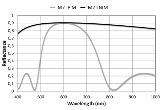
V.2.2 NIM/PIM configurations
Low-index NIM layers
If we replace the low-index L layers of the previous all-PIM quarter-wavelength Bragg mirror by NIM layers (, = -1.48, = 101.35 nm), the formula of the stack becomes
Air / HHHH / Glass
and the computation of its optical properties can be achieved by replacing these NIM layers by their correlated PIM Mirror Images ( = 1.48, = -101.35 nm). The black line in Fig. 1 shows the spectral variation of the reflectance of this M7 LNIM mirror at zero AOI. We observe a spectacular increase in the spectral bandwidth of this mirror induced by the use of low-index NIM layers. This bandwidth now covers almost the entire wavelength range, from 400 to 1000 nm, whereas the spectral width of the corresponding PIM configuration does not exceed 250 nm.
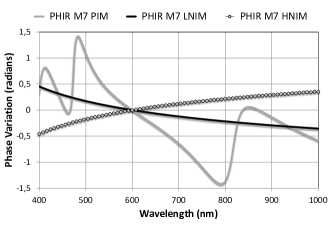
High-index NIM layers
For a stack formula
Air / LLL / Glass
where is a high-index quarter-wavelength NIM layer ( = -2.24, = 66.96 nm), the result of the simulation (spectral dependence of the reflectance) is exactly the same as that obtained for the low-index NIM layers configuration. The only difference is related to the phase change at the reflection , defined by whose spectral dependence is shown in Fig. 2 (gray disks with black contour) together with those of the M7 All-PIM (gray line) and M7 LNIM (black line) configurations. The spectral dependence of this phase quantity is indeed equal and opposite to that of the low-index NIM layers configuration (with four high-index NIM layers in this last configuration compared to three low-index NIM layers in the previous one).
V.3 Fabry-Perot bandpass filter
V.3.1 Standard PIM configuration
Let us now consider a Fabry-Perot bandpass filter including two identical M7 mirrors surrounding a 2B spacer layer. The corresponding multilayer stack is then described by the following formula
Air / HLHLHLH 2B HLHLHLH / Glass
where H and B have the same meaning as above. The spectral dependence of the transmittance of this bandpass filter is shown in Fig. 3.
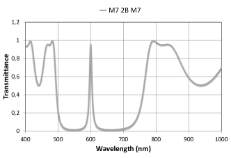
The full width at half maximum (FWHM) of the passband is about 8 nm whereas that of the stopband is around 150 nm with a maximum rejection level of -18.6 dB.
V.3.2 NIM/PIM configurations
First analysis
Taking into account the difference in phase behavior of the NIM and PIM quarter-wavelength Bragg mirrors discussed in Section V.2.2, we have to first consider three different NIM/PIM Fabry-Perot configurations, i.e.
-
•
the M7LNIM 2B M7LNIM configuration, in which the low-index quarter-wavelength PIM layers of both M7 mirrors are replaced by corresponding NIM layers,
-
•
the M7HNIM 2B M7HNIM configuration, in which the NIM layers are now the high-index layers of both M7 mirrors, and
-
•
the M7LNIM 2B M7HNIM configuration, which corresponds to a design intermediate to the two previous ones.
The spectral dependence of the transmittance of these three Fabry-Perot configurations is shown in Fig. 4.
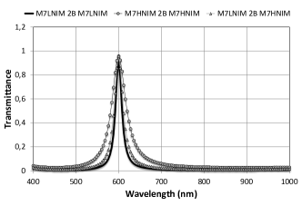
The replacement of some PIM layers by NIM layers in the standard design of this Fabry-Perot (FP) bandpass filter induces then, for the three considered configurations, a large increase in the width of the stopband (more than a factor of 4) which allows us to avoid the use of blocking filters for most potential applications. However the spectral properties of these three configurations are not exactly identical, and, in order to highlight their differences, we have summarized in Table 1, for each FP configuration, the values of the two parameters introduced in the previous section, i.e. the filter bandwidth (FWHM) and the maximum rejection level in the stopband.
| FP stack formula | (nm) | (dB) |
|---|---|---|
| H 2B H | 8.5 | -18.6 |
| H 2B H | 16.8 | -21.3 |
| 2B | 40.3 | -15.8 |
| H 2B | 23.6 | -19.5 |
The bandwidth of these Fabry-Perot filters is between 8.5 nm (for the standard configuration) and 40.3 nm (for the configuration using high-index quarter-wavelength NIM layers), whereas the rejection level is not drastically affected by these design changes (being between -15.8 dB and -21.3 dB).
Discussion
To explain the differences in behavior observed among these various configurations, we must consider the overall round-trip phase of each Fabry-Perot configuration and study its spectral dependence. We have indeed at normal incidence
| (40) |
where is the optical path difference corresponding to the round-trip of light in the spacer layer and (respectively ) is the phase change at the reflection of light on the upper mirror (respectively lower mirror) of the Fabry-Perot cavity. This means that, for an M7 2B M7 configuration, we have to consider for the term a seven-layer quarter-wavelength Bragg mirror deposited on a glass substrate with silica as incident medium and for the term a seven layers quarter-wavelength Bragg mirror deposited on air with silica, again, as the incident medium.
The quantity is given here by
| (41) |
where the index sp is related to the spacer of the Fabry-Perot cavity. At the design wavelength, we thus have Macleod_2010
| (42) |
where is in .
In general, the transmittance of a Fabry-Perot multilayer filter around the design wavelength is given by
| (43) |
with
| (44) |
where (respectively ) is the reflectance of the upper mirror (respectively lower mirror) of the Fabry-Perot cavity. Accordingly, the bandpass width is defined by
| (45) |
This means that the bandwidth of the Fabry-Perot is directly driven by the spectral dependence of the overall round-trip phase . Moreover, in the linear regime, we can write Lequime_2009
| (46) |
where the linear dependence of the overall round-trip phase around the design wavelength is given by
| (47) |
For all the Fabry-Perot configurations considered in Table 1, the spacer layer is half-wave at the design wavelength, whereby relation (47) becomes
| (48) |
Thus, minimizing the linear dependence of the overall round-trip phase (and accordingly maximizing the related spectral bandwidth ) requires the use of mirrors characterized by a positive spectral dependence of the global phase change at the reflection for the design wavelength.
| FP stack formula | ||||
|---|---|---|---|---|
| H 2B H | -0.00929 | -0.00950 | -0.02926 | 8.5 |
| H 2B H | -0.00216 | -0.00212 | -0.01475 | 16.8 |
| 2B | 0.00216 | 0.00212 | -0.00619 | 40.1 |
| H 2B | -0.00216 | 0.00212 | -0.01052 | 23.6 |
The spectral bandwidths predicted by using this approach are summarized in Table 2 for the four previous Fabry-Perot configurations. They are in perfect accordance with those given in Table 1.
The same approach (minimizing the spectral dependence of the overall round trip phase ) can be used to design a kind of white Fabry-Perot cavity, i.e. a multilayer cavity that spontaneously exhibits a resonant behavior over a very large spectral range. The description of this optimization scheme exceeds the frame of this paper and will be described further in a dedicated article Lequime .
V.4 Antireflection coatings
V.4.1 Standard PIM configurations
We restrict our study to single-layer and double-layer antireflection stacks providing zero reflectance at a given design wavelength (here 600 nm) and normal incidence. Theoretical analyses using admittance formalism Macleod_2010 shows that we have only two possible configurations
-
•
a single-layer solution (1A) whose refractive index and optical thickness are imposed (, at the design wavelength), or
-
•
a double-layer solution for which the phase delays of both layers must satisfy the following set of equations
(49) In this case, we can either choose the same low-index and high-index materials as above, i.e. () and () and thereby define two different solutions following the sign of
Solution 2A: Air / 1.312L 0.317H / Glass
Solution 2B: Air / 0.688L 1.683H / Glass
or we can impose that the optical thicknesses of both layers be equal to , which leads to the following relation
(50) If we use silica for the top layer (), the refractive index of the bottom layer will be equal to 1.825, the formula of the corresponding stack being simply given in this case by
Solution 2C: Air / L H / Glass
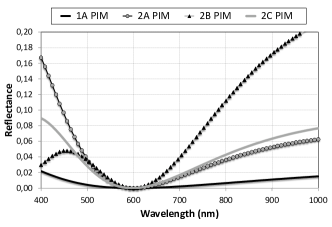
The Figure 5 shows the spectral dependence of the reflectance of the single-layer solution (1A) as well as the three double-layer solutions (2A, 2B and 2C) at zero AOI. Clearly the single-layer solution is the best one in terms of behavior throughout the spectral range.
V.4.2 NIM/PIM configurations
In accordance with the conclusion of Section V.1, we do not need to analyze the optical properties of all-NIM antireflection coatings, because the spectral dependence of their reflectance would be identical to those shown in Fig. 5.
Hence we focus our further analysis on the NIM/PIM double-layer configurations by considering only the stacks in which the high-index PIM layer is replaced by a NIM layer (and, except for the phase change at reflection, the replacement of the only low-index layer would provide obviously identical results). In this case, the set of equations (49) remains exactly the same, but the results in terms of physical thickness must now be negative. The three NIM/PIM antireflection double-layer stacks are thus described by the formulas
Solution 2: Air / 1.312L 1.683 / Glass
Solution 2: Air / 0.688L 0.317 / Glass
Solution 2: Air / L / Glass
and the spectral dependence of their reflectance is shown in Fig. 6 (where, in order to exemplify the differences among the various curves, the vertical scale is expanded by a factor of 4 with respect to Fig. 5).
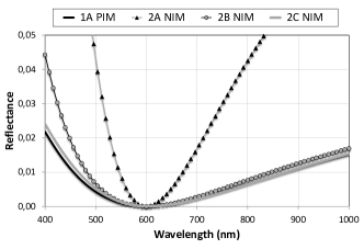
We observe that the spectral dependence of the residual reflectance provided by solution 2 is nearly identical to that of solution 1A. The use of a NIM layer in a double-layer configuration is then a way to synthesize a virtual index in accordance with the single layer condition. Nevertheless, it does not allow us to achieve perfect spectral behavior, i.e., zero reflectance at any wavelength over a wide spectral range (400-1000 nm for instance).
VI Conclusion
In this paper, we hope to have conclusively shown the usefulness of the admittance formalism to model the optical properties of multilayer stacks including negative index materials. The most attractive results concern the quarter-wavelength Bragg mirrors and the multilayer Fabry-Perot filters, and the ability to tailor the phase properties of such multilayer structures open interesting avenues for design of white Fabry-Perot. Other potential applications of the admittance formalism include the analysis of zero-index stop band structures which consist in an alternation of layers of opposite refractive indices Li_2003 . Finally, it could be really attractive to apply this approach to the study of optical properties of the same multilayer structures with more realistic spectral material properties, as defined by V. A. Podolskiy Podolskiy_2003 , V. M. Shalaev Shalaev_2005 or more recently Z. H. Jiang Jiang_2013 .
References
- (1) V. M. Shalaev, ”Optical negative-index metamaterials,” Nat. Photon. 1, 41-48 (2007).
- (2) Z. H. Jiang, S. Yun, L. Lin, J. A. Bossard, D. H. Werner, and T. S. Mayer, “Tailoring Dispersion for Broadband Low-loss Optical Metamaterials Using Deep-subwavelength Inclusions,” Scientific Reports 3, 01571 (2013).
- (3) B. Gralak, S. Enoch, and G. Tayeb, “Anomalous refractive properties of photonic crystals,” J. Opt. Soc. Am. A 17, 1012-1020 (2000).
- (4) M. Notomi, “Theory of light propagation in strongly modulated photonic crystals: Refraction like behavior in the vicinity of the photonic bang gap,” Phys. Rev. B 62, 10696-10705 (2000).
- (5) V. G. Veselago, ”The electrodynamics of substances with simultaneously negative values of and ,” Sov. Phys. Usp. 10, 509–514 (1968, Russian text 1967).
- (6) R. A. Shelby, D. R. Smith, and S. Schultz, ”Experimental Verification of a Negative Index of Refraction,” Science 292, 77-79 (2001).
- (7) S. Kocaman, M. S. Aras, P. Hsieh, J. F. McMillan, C. G. Biris, N. C. Panoiu, M. B. Yu, D. L. Kwong, A. Stein, and C. W. Wong, “Zero phase delay in negative-refractive-index photonic crystal superlattices,” Nat. Photon. 5, 499-505 (2011).
- (8) J. B. Pendry, ”Negative Refraction Makes a Perfect Lens,” Phys. Rev. Lett. 85, 3966-3969 (2000).
- (9) J. B. Pendry, D. Schurig, D. R. Smith, ”Controlling Electromagnetic Fields”. Science 312, 1780–1782 (2006)
- (10) F. Zolla, S. Guenneau, A. Nicolet, and J. B. Pendry, “Electromagnetic analysis of cylindrical invisibility cloaks and the mirage effect,” Opt. Lett. 32, 1069-1071 (2007).
- (11) D. Schurig, J. J. Mock, B. J. Justice, S. A. Cummer, J. B. Pendry, A. F. Starr, D. R. Smith, ”Metamaterial Electromagnetic Cloak at Microwave Frequencies”. Science 314, 977–980 (2006).
- (12) T. Ergin, N. Stenger, P. Brenner, J. B. Pendry, M. Wegener, “Three-Dimensional Invisibility Cloak at Optical Wavelengths,” Science 328, 337-339 (2010).
- (13) H. A. Macleod, Thin-film optical filters, 4th ed. (CRC Press, 2010).
- (14) S. A. Ramakrishna and O. J. F. Martin, ”Resolving the wave vector in negative refractive index media,” Opt. Lett. 30, 2626-2628 (2005).
- (15) Y. F. Chen, P. Fischer, and F. W. Wise, ”Negative Refraction at Optical Frequencies in Nonmagnetic Two-Component Molecular Media,” Phys. Rev. Lett. 98, 067402 (2005).
- (16) T. G. Mackay and A. Lakhtakia, Comment on ”Negative Refraction at Optical Frequencies in Nonmagnetic Two-Component Molecular Media,” Phys. Rev. Lett. 96, 159701 (2006).
- (17) S. A. Ramakrishna, Comment on ”Negative Refraction at Optical Frequencies in Nonmagnetic Two-Component Molecular Media,” Phys. Rev. Lett. 98, 059701 (2007).
- (18) Y. F. Chen, P. Fischer, and F. W. Wise, Reply to Comments on ”Negative Refraction at Optical Frequencies in Nonmagnetic Two-Component Molecular Media,” Phys. Rev. Lett. 98, 059702 (2007).
- (19) M. I. Stockman, ”Criterion for Negative Refraction with Low Optical Losses from a fundamental Principle of Causality,” Phys. Rev. Lett. 98, 177404 (2007).
- (20) T. G. Mackay and A. Lakhtakia, Comment on ”Criterion for Negative Refraction with Low Optical Losses from a fundamental Principle of Causality,” Phys. Rev. Lett. 98, 189701 (2007).
- (21) A. A. Govyadinov, V. A. Podolskly, and M. A. Noginov, ”Active metamaterials: Sign of refractive index and gain-assisted dispersion management,” Appl. Phys. Lett. 91, 191103 (2007).
- (22) R. Cooke, Classical algebra: its nature, origins, and uses (John Wiley and Sons, 2008).
- (23) S. A. Ramakrishna, ”Physics of negative refractive index materials,” Rep. Prog. Phys. 68, 449–521 (2005).
- (24) C. Amra, ”First-order vector theory of bulk scattering in optical multilayers,” J. Opt. Soc. Am. A 10, 365-374 (1993)
- (25) C. Fu, Z. M. Zhang, and D. B. Tanner, ”Radiative properties of multilayer thin films with positive and negative refractive indices,” in Proceedings of IMECE2002 (American Society of Mechanical Engineers, 2002), Paper 32771
- (26) M. Lequime, “Spectral properties of planar multilayer microcavities,” presented at the International Conference Frontiers of Optical Coatings FOC 2009, Xi’An, P. R. China, 11-15 Oct. 2009
- (27) M. Lequime, B. Gralak, S. Guenneau, M. Zerrad, and C. Amra, ”Negative Index Materials: The Key to ”White” Multilayer Fabry-Perot,” to be published (2013)
- (28) J. Li, L. Zhou, C. T. Chan, and P. Sheng, ”Photonic Band Gap from a Stack of Positive and Negative Index Materials,” Phys. Rev. Lett. 90, 083901 (2003).
- (29) V. A. Podolskiy, A. K. Sarychev, and V. M. Shalaev, ”Plasmon modes and negative refraction in metal nanowire composites,” Opt. Express 11, 735-745 (2003).
- (30) V. M. Shalaev, W. Cai, U. K. Chettiar, H. K. Yuan, A. K. Sarychev, V. P. Drachev, and A. K. Kildishev, ”Negative index of refraction in optical metamaterials,” Opt. Lett. 30, 3356-3358 (2005).