Optimisation of fractal spaceframes under gentle compressive load
Abstract
The principle of hierarchical design is a prominent theme in many natural systems where mechanical efficiency is of importance. Here we establish the properties of a particular hierarchical structure, showing that high mechanical efficiency is found in certain loading regimes. We show that in the limit of gentle loading, the optimal hierarchical order increases without bound. We show that the scaling of material required for stability against loading to be withstood can be altered in a systematic, beneficial manner through manipulation of the number of structural length scales optimised upon. We establish the relationship between the Hausdorff dimension of the optimal structure and loading for which the structure is optimised. Practicalities of fabrication are discussed and examples of hierarchical frames of the same geometry constructed from solid beams are shown.
pacs:
46.32.+x 46.70.De 46.25.CcI Introduction
Hierarchical designs are found throughout nature where highly mechanically efficient load bearing structures are required Lakes . Trabecular bone serves as a prime example where requirements for stiffness and strength are met through utilising structural hierarchy Huiskes . Allometric scaling has been observed in the lattice-like sub-structure of the trabecular bone: in mammals, lattice connectivity increases and trabeculae thickness decreases with decreasing mass of animal Trab_Allo . The structure of fossilised ammonites have long been appreciated to exhibit a fractal structure in their suture lines Saunders_2 . Although other driving factors have been proposed Per_Palm , it has been persistently hypothesised that higher degrees of structural hierarchy are responsible for increased resilience to pressure bearing (for a given mass of construction material) Saunders_2 ; Oloriz ; Long . It has recently been shown that hierarchical and fractal-like suture joints can be used to tailor mechanical properties, load resistance and flaw tolerance Li . Further examples include spider capture silk Du_spider ; Zhang , nacre Nac_1 and gecko setae Gao ; Yao_1 , all exhibit hierarchical structures with geometric parameters tailored for different loading conditions.
Recent theoretical works have found that efficient structures can be generated through a self similar design principle Farr_and_Mao ; Ray_hol ; Ray_pressure . Under external pressure and gentle compressive loading the same tendencies are found: with decreasing load, the optimal number of hierarchical orders is found to increase and a tendency towards more slender components is observed Farr_and_Mao ; Ray_hol ; Ray_pressure ; Ray_fab .
Advances in construction techniques have made it possible to fabricate designs with structural order on a wide range of length-scales. The construction of frames with a photosensitive polymer can be used in conjunction with other techniques such as electroless nickel plating and etching, to create frames with the same geometry but constructed from hollow, metallic tubing Schaedler ; Jacobsen ; Saleh . Using such techniques, hierarchical metallic lattices, for example, have been created with structural order ranging from the nano- to the centimetre scale Schaedler . Such techniques make it possible to design and create materials where beneficial properties of the macrostructure are bought about through the prudent choice of design parameters at structural length scales orders of magnitude smaller.
Here, a hierarchical spaceframe design constructed from hollow tubes is analysed in full and its benefits over a solid beam construction are discussed. A spaceframe constructed from solid beams is created through rapid prototyping techniques showing the fabrication of the thin walled structure to be a plausible goal. The optimal number of hierarchical levels for a given loading is found and fractal dimension of the optimal structure is calculated. We discuss particular issues of practical importance when designing and fabricating hierarchical structures.
II Theory
II.1 Solid beam and generation-0
To serve as a reference, we first consider the problem of obtaining the amount of material that is required, , to construct a beam of length , freely hinged at its ends, stable under a compressive load . If we take an initially straight, solid, slender beam with circular cross section, constructed from an isotropic material, we see that the Euler buckling mode of the strut gives the first limit on stability. The load at which this instability is reached is given by:
| (1) |
where is the second moment of area ( for a solid beam with circular cross-section) and is the Young’s Modulus of the material. Suitable non-dimensional variables for this problem are defined as,
| (2) | |||
| (3) |
measuring loading and volume respectively. For a given , setting such that the beam is on the point of instability due to Euler buckling gives us the minimum volume required for stability. This value of is found to be,
| (4) |
Thus the minimum non-dimensional volume of material, , required for stability for a given loading, , can be expressed as:
| (5) |
As a comparison, it is noted that the volume of material required for stability under tension varies linearly with the loading parameter, or . In all practical applications the non-dimensional parameters and are much smaller than 1. Thus, to support a given magnitude of loading over a given distance requires less material if the support is under tension rather than compression. Furthermore, it is seen that splitting a given load over two tension members, each supporting half the load, has little consequence on the total volume of material required; on the other hand, as a result of the above scaling, the amount of material required increases greatly if multiple compression members are used to support a given load Cox .
If instead the circular beam is taken to be hollow, with thin walls, two restrictions are seen to apply to the loading. The first is given by Eq. (1) with where is the thickness of the cylinder wall. Secondly, a short wavelength failure mode must be considered, Koiter buckling Koiter , giving a second inequality:
| (6) |
where is the Poisson ratio. Setting the geometry of the beam to be such that Euler buckling and Koiter buckling occur at the same value of loading, it is straightforward to show that
| (7) |
In the regime this change in scaling law represents a saving in material over the solid beam. In this work, the hollow cylinder will be referred to as the generation-0 structure.
II.2 Hollow generation-1 structure

The generation-1 structure is a simple spaceframe made up of octahedra which separate two end tetrahedra: the geometry of the spaceframe is shown in figure 1 (a) with . Here we consider the component cylinders to be hollow with thin walls. If the length of the whole structure is defined as , and the length of an individual component beam is , then,
| (8) |
Assuming all beams in the structure to be made up of identical beams that exhibit Hookean behavior for loading less than the Euler limit and whose spring constant is given by,
| (9) |
where is the cross-sectional area of the beam. For large enough , the whole frame can be shown to have a bending stiffness, , and spring constant, given by:
| (10) | |||
| (11) |
where is a constant found to be Farr_and_Mao . If the structure is oriented such that the end points of the tetrahedra are aligned along the -axis in Cartesian coordinates, then on loading these end points with a force in a compressive manner, it is found that that all beams parallel with the plane are under tension. Assuming the beams under tension making up the end tetrahedra support a load of while other tension members support a load of . It is found that all other beams support a compressive load. The beams connected to the end points are acted on by a force of
| (12) |
while all other beams under compression take half this load. In the generation-1 frame, there are 3 failure modes: Koiter buckling of the individual beams and Euler buckling of both the composite frame and the individual beams. The three parameters that we wish to optimise over are , and . We proceed by defining
| (13) |
and stating that the beams connected to the loading points of the structure are on the point of simultaneous failure due to both Euler and Koiter buckling. Through use of Eqs. (1, 6, 12 & 13) it follows that:
| (14) | |||||
| (15) |
Then, using Eqs. (1, 8 - 10 & 12 - 15) and setting the whole spaceframe to be on the point of Euler buckling, it is found that
| (16) |
where is the floor function. Then, using Eqs. (8 & 12) it is found that,
| (17) |
Using Eqs. (8, 14 & 15), the non-dimensional volume is found to be,
| (18) |
thus, through use of Eq. (17),
| (19) |
This expression represents a gain in efficiency over both the solid and hollow beams in the limit . For comparison a spaceframe constructed from solid beams scales as . Thus it is seen, in the limit of gentle loading, the structure presented here is more efficient.
II.3 Generation- optimisation
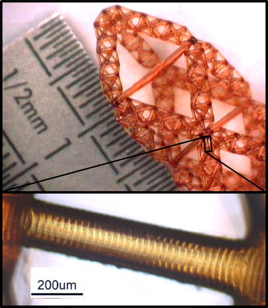
The generation- structure can be created through an iterative procedure. In creating the generation-1 structure, the simple, hollow beam that makes up the generation-0 structure is replaced with a spaceframe. It is an analogous step that takes us from the generation-1 structure to the generation-2 structure: all simple beams in the structure that are loaded under compression are replaced by (scaled) generation-1 frames. Thus, it is noted, a generation- constructed from hollow tubes has characteristic length scales upon which it could fail. The notation used here will follow that in Ref. Farr_and_Mao :] a given property of the structure that is recurrent on different hierarchical levels of the structure will be denoted , which represents the property on the -th level in a generation- structure ( and denotes the smallest and largest length scale in the structure respectively). The generation-1, 2 and 3 structures are shown in stereographic form in figure 1. Shown in figure 2 is the upper tetrahedron and octahedron of a generation-2 spaceframe constructed through rapid prototyping techniques.
The properties of any (sub)frame can be related to the smallest component beams through expressions involving . These expressions are dependent only on the geometry of the spaceframe and are given by:
| (20) | |||||
| (21) | |||||
| (22) | |||||
| (23) |
where is the effective spring constant of all (sub)structures of length , and is the applied compressive load to each substructure of length .
It is seen that to avoid Euler buckling at each hierarchical length scale, the constraint
| (24) |
must be imposed for all . Given that the smallest beams are made of hollow tubes, the possibility of Koiter buckling must be taken into account. This constraint on loading provides us with the inequality
| (25) |
| Generation | Mass (kg) | |||
|---|---|---|---|---|
| Hollow - 0 | - | - | - | 1421 |
| Solid - 0 | - | - | - | |
| Hollow - 1 | 44 | - | - | 487 |
| Solid - 1 | 140 | - | - | 2920 |
| Hollow - 2 | 22 | 22 | - | 439 |
| Solid - 2 | 46 | 47 | - | 1790 |
| Hollow - 3 | 13 | 14 | 14 | 533 |
| Solid - 3 | 23 | 23 | 24 | 2180 |
The parameters over which we optimise are , (which are assumed to be constant over the generation-1 structure), and . Defining the geometry such that Euler buckling and the short wavelength Koiter buckling occur simultaneously in the beams of length , through use of Eqs. (6, 13 & 24) with , it can be shown that and are given by:
| (26) | |||||
| (27) |
Using these experssions and Eq. (9) it can be shown that
| (28) |
Then using Eqs. (13 - 15, 21, 23, 20 & 24), setting all (sub)frames to be on the point of failure due to Euler buckling, it can be observed that,
| (29) |
and, for ,
| (30) |
In this calculation, the spring constant of the simple beams under tension at any given hierarchical level are chosen to be equal, they are set as that of the spaceframe of the same length. To achieve this, using Eqs. (21, 22, 26, 27 & 28) we see that the radii, , of the tension resisting beams of length are,
| (31) |
and remains constant for the whole structure. For , it is found that,
| (32) | |||
| (33) |
To obtain the former equation, Eqs. (2, 13, 20 & 21) were used, and in the latter, Eqs. (3, 21, 26 & 27). The scaling of material required to make a stable structure out of hollow tubes, to leading order, is therefore shown to obey:
| (34) |
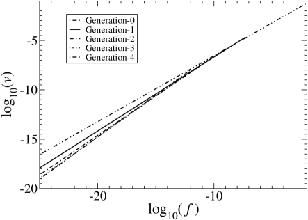
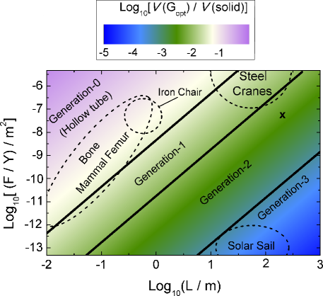
Combining Eqs. (32 & 33) and eliminating a full expression for the volume required for stability under a given load can be obtained, and this is plotted in figure 3, where the scaling of Eq. (34) is seen to dominate. For , this design shows that considerable gains in efficiency are possible through increasing the hierarchical order of the structure. In the limit the scaling of material required for stability against loading to be withstood is seen to tend to that found for a simple beam under tension. For a given material, increases with increasing . Thus, for all non-zero values of loading, the optimal generation is found to be finite. The progression of the optimal generation of the hierarchical frame is shown in figure 4 where the material saving and optimal generation are plotted for various values of and . We see that, for a given , low and high (or small ) lead to higher generation numbers being more efficient.
The optimisation procedure described above results in a structure that sets
| (35) | |||||
| (36) |
and in the limit , is approximated by
| (37) |
The analysis above assumes that on all length scales elastic failure is the active failure mode. Plotted in figure 5 is the slenderness ratio for the smallest beams and the minimum aspect ratio of all the spaceframes in the structure, as defined by the expressions:
| (38) | |||||
| (39) |
where is the maximum distance of any material making up a spaceframe of length from its neutral axis. As the loading parameter becomes smaller, the slenderness ratio increases, thus it is likely in the regime where maximal gains from the hierarchical construction are found, the elastic (as opposed to plastic) failure mode is dominant.
III Fractal Dimension
The structures described above are hierarchical over a certain range of length scales. Within this range, one can calculate an effective Hausdorff dimension, , through considering the self similarity of the structure at different hierarchical levels. It is found that it is dependent on and is given by the following expression:
| (40) |
The values shown in figure 6 are confirmed through a box-counting technique. The box counting method is used with a set of cubes with side length of or ( takes the same values as in Eq. (39)). For small enough box sizes (below the range of length scales where the structure is hierarchical), a structure optimised for a finite force will have a Hausdorff dimension of 3. For suitably small but finite values of loading however, the set will yield a non-trivial Hausdorff dimension. As a result of the variation of with , the fractal dimension of the optimal structure described above is not a constant over all length scales. The upper and lower bounds for the fractal dimension can, however, be found. These bounds are shown in figure 6 where they are plotted against the loading parameter for which the structure is optimised. A sub-optimal structure with a constant Hausdorff dimension could be created by setting where is taken from the optimised structure. Such a structure, with and taken from Eqs. (26) and (27) respectively, would be stable for loading greater than and would attain the upper bound in Hausdorff dimension shown in figure 6. In the limit of it is seen from Eqs. (29, 30, 40) that the limit of the fractal dimension tends to 1.
IV Fabrication of hierarchical structures
With the development of novel fabrication techniques the engineering challenge in creating these structures is not insurmountable. In most terrestrial applications, it is found the optimal level of hierarchy, for this structure, will not exceed 3. This puts some restrictions on, but does not negate, the engineering challenge.
We have fabricated fractal compression members using a modified EnvisionTEC Perfactory® type III mini system from a photosensitive polymer, EnvisionTEC R05 Ray_fab . This mask-projection based photopolymerisation system has a pixel digital light processing projector allowing a resolution of 5. The structure shown in figure 2 was first modelled in 3D as an STL file, before being split into numerous thin layers and stored as a job file using Perfactory RP proprietary software. These layers are visible in the final manufactured structure, see figure 2. Light with wavelength approximately 475nm is then passed through the projector and focused onto the resin surface for polymerisation of the exposed areas. The sample is then washed using ispropanol in an ultrasonic bath and left to dry. A postcuring procedure is followed using an EnvisionTEC Otoflash System to harden the material. An alternative material, EnvisionTEC RC25 (Nanocure), has also been used to create frames of the same geometry using the same fabrication procedure but without the necessity for postcuring Ray_fab .
The structure shown in figure 2 is a generation-2 hierarchical frame with and . The smallest beams in the structure have radii of approximately 0.15mm and lengths of 1.35mm. The layer thickness of the growth was 25m.
Mechanical testing of the structure presented here has been undertaken Ray_fab and good agreement between the structure’s performance and finite element simulations is found. It is noted that, in this case, the bending moments induced at the beam ends due to deformation result in failure at lower loads than predicted in the theory presented here. It is also noted that the “slender beam” approximation used here is not well met by structures fabricated to date.
V Conclusions
We have shown that through a hierarchical design principle a highly efficient compression bearing structure can be created. Analysing all possible modes of failure, at each length scale, we have shown that the scaling of volume of material required for stability against a given loading can be systematically varied in an advantageous manner. We have shown that the use of hollow, rather than solid beams, changes the scaling in a manner analogous to increasing the generation number by 1. More generally it is noted that for hierarchical structures optimised for gentle compressive loading here and in Refs. Farr_and_Mao ; Farr_Efficient_Shell , a structure with characteristic length scales of failure obeys a relationship of . We have also shown the dependence of fractal dimension of the optimal structure on the applied load at failure. The dependence on loading of the optimal number of levels of hierarchy for this structure has also been obtained.
Further optimisation of the structure is possible: at every hierarchical level, there exist two different loading conditions for beams/sub-frames under compression. Despite this, in the work presented here, all beams and sub-frames at a particular hierarhical level are equivalent; variation of sub-frame charateristics, optimising each one for its particular loading would result in a more efficient structure.
The use of these hierarchical structures will be dependent on cost of production and robustness of the structure in their intended use. The potential trade-off between mechanical efficiency and robustness of hierarchical structures must be investigated further. It is noted that the structure presented above is minimally rigid. Thus, for this particular structure, modeled with freely hinged joints, removal of a single beam (or subframe) will result in collapse of the structure at all larger lengthscales. In the case of non-freely hinged joints, some rigidity will be maintained however a transition from stretching to bending dominated regimes will occur.
Finally it is noted that the smallest possible building blocks for these hierarchical designs are single and multi wall carbon nanotubes. It has been shown that both Koiter and Euler buckling of these tubes are closely approximated by Eqs. (1) and (6), up to a prefactor in the case of multi-walled carbon nanotubes CNTs . Thus it is expected that the analysis shown previously will still hold. Alternative structural elements include hollow nanotubes constructed through atomic layer deposition Ikkala_tubes . Ultimately, molecular self-assembly may offers a fabrication method for these intricate hierarchical materials with structural features from the nanoscale up self_assembly ; inorganic_rods .
VI Acknowledgements
The authors would like to acknowledge the work of Joel Segal, Ranbir Singh and Fred Grillet, from the Department of Mechanical, Materials and Manufacturing Engineering, University of Nottingham also that of Mark Strickland of the Faculty of Engineering at the University of Nottingham.
Appendix A Stereolithography files
The fabrication of these intricate structures has become possible through advances in 3-d printing. With the increasing availability and resolution of commercial printers, the authors have made some example stereolithography (.stl) files freely available online Yongs .
References
- (1) Lakes, R., Nature, 361, 511-515, (1993)
- (2) R. Huiskes, R. Ruimerman, G. H. van Lenthe, and J. D. Janssen, Nature, 361, 511 (1993)
- (3) M. Doube, M. M. Klosowski, A. M. Wiktorowicz-Conroy, J. R. Hutchinson and S. J. Shefelbine, Proc. R. Soc. B, 278, 3067 - 3073 (2011)
- (4) W. B. Saunders, D. M Work, and S. V. Nikolaeva, Science, 286, 760 (1999)
- (5) J. A. Pérez-Claros, P. Palmqvist and F. Olóriz, Mathematical Geology, 34, 323-343, (2002)
- (6) F. Olóriz, P. Palmqvist, and J. A. Pérez-Claros, LETHIA, 30, 191-204, (1997)
- (7) C. A. Long, J. Morphology, 185, 185-195 (1985)
- (8) Y. Li, C. Ortiz and M. C. Boyce, Phys Rev E, 85, 031901 (2012)
- (9) N. Du, X. Y. Liu, J. Narayanan, L. Li, M. L. M. Lim and D. Li, Biophysical Journal, 91, 4528 - 4535 (2006)
- (10) H. Zhou and Y. Zhang, Physical Review Letters, 94, 028104 (2005)
- (11) H. D. Espinosa, A. L. Juster, F. J. Latourte, O. Y. Loh, D. Gregoire and P. D. Zavattieri, Nature Communications, 2, 173 (2011)
- (12) H. Gao, X. Wang, H. Yao, S. Gorb and E. Arzt, Mechanics of Materials, 37, 175-185, (2005)
- (13) H. Yao and H. Gao, Journal of the Mechanics and Physics of Solids, 54, 1120-1146 (2006)
- (14) R. S. Farr and Y. Mao, EPL, 84, 14001 (2008)
- (15) D. Rayneau-Kirkhope, Y. Mao and R. S. Farr, Physical Review Letters, 109, 204301 (2012)
- (16) D. Rayneau-Kirkhope, R. S. Farr and Y. Mao, EPL, 93, 34002 (2011)
- (17) D. Rayneau-Kirkhope, R. S. Farr, Y. Mao and J. Segal, Mechanics Research Communications, 46, 41-46 (2012)
- (18) T. A. Schaedler, A. J. Jacobsen, A. Torrents, A. E. Sorensen, J. Lian, J. R. Greer, L. Valdevit and W. B. Carter, Science, 334, (2011)
- (19) A. J. Jacobsen, W. Barvosa-Carter and S. Nutt, Advanced Materials, 19, 3892-3896, (2007)
- (20) N. Saleh, N. Hopkinson, R. J. M. Hague and S. Wise, Rapid Prototyping Journal, 10, 305-315 (2004)
- (21) Cox, The Design of Sturctures of the Least Weight (Pergamon, New York, 1965)
- (22) W. T. Koiter, Ph.D. thesis, Technische Hogeschool Delf, 1945
- (23) Liebherr, www.liebherr.com, 4 August 2012
- (24) B. Wie, Journal of Guidance, Control and Dynamics, 24, 526 - 535 (2004)
- (25) Yong Mao, University of Nottingham, www.nottingham.ac.uk/ ppzym/print, 14 May 2013
- (26) R. S. Farr, Phys. Rev. E, 76, 056608 (2007)
- (27) N. Hu, K. Nunoya, D. Pan, T. Okabe and H. Funkunaga, Int. J. Solids Struct., 44, 6535 (2007)
- (28) R. H. A. Ras, M. Kemell, J. de Wit, M. Ritala, G. ten Brinke, M. Leskela and O. Ikkala, O., Advanced Materials, 19, 102 - 106 (2007)
- (29) S. Zhang, Nature Biotechnology, 21, 1171 - 1177 (2003)
- (30) K. Liu, N. Zhao and E. Kumacheva, Chem. Soc. Rev., 40, 656 - 671 (2011)
- (31) EnvisionTEC R05 and RC25 (Nanocure) Techincal Data, www.envisiontec.de, 22 November 2010