∎
Tel.: +49-(0)30-8104-3562
Fax: +49-(0)30-8104-1827
22email: thibault.derrien@gmail.com 33institutetext: Tatiana E. Itina 44institutetext: Laboratoire Hubert Curien (LabHC), UMR CNRS 5516 - Université Jean Monnet Bat. F, 18 rue du Professeur Benoit Lauras, 42000 Saint-Etienne, France 55institutetext: Sandra Höhm, Arkadi Rosenfeld 66institutetext: Max-Born-Institut für Nichtlineare Optik und Kurzzeitspektroskopie (MBI), Max-Born-Straße 2A, D-12489 Berlin, Germany
Rippled area formed by surface plasmon polaritons upon femtosecond laser double-pulse irradiation of silicon: the role of carrier generation and relaxation processes
Abstract
The formation of laser-induced periodic surface structures (LIPSS, ripples) upon
irradiation of silicon with multiple irradiation sequences consisting of
femtosecond laser pulse pairs (pulse duration 150 fs, central wavelength 800 nm)
is studied numerically using a rate equation system along with a two-temperature
model accounting for one- and two-photon absorption and subsequent carrier
diffusion and Auger recombination processes. The temporal delay between the
individual equal-energy fs-laser pulses was varied between and ps for
quantification of the transient carrier densities in the conduction band of the
laser-excited silicon. The results of the numerical analysis reveal the
importance of carrier generation and relaxation processes in fs-LIPSS formation
on silicon and quantitatively explain the two time constants of the delay dependent
decrease of the Low-Spatial-Frequency LIPSS (LSFL) area observed experimentally. The role of carrier generation, diffusion and recombination are quantified individually.
DOI: 10.1007/s00339-013-8205-2. The final publication is available at http://link.springer.com.
Keywords:
Laser-induced periodic surface structure (LIPSS) Femtosecond laser Silicon Surface-Plasmon-Polariton Double-pulsepacs:
79.20.Ds 73.20.Mf 06.60.Jn 68.35.Bg1 Introduction
The irradiation of solids with multiple linear polarized femtosecond laser pulses at fluences close to the damage threshold leads to the formation of laser-induced periodic surface structures (LIPSS) on the surface of almost all materials Borowiec2003 ; Huang2009a ; Chakravarty2011 ; Bonse2012 . For strong absorbing materials such as metals or semiconductors, in most cases low-spatial-frequency LIPSS (LSFL) are observed with a period close to the irradiation wavelength Borowiec2003 ; Huang2009a ; Bonse2012 . These LSFL are generated by interference of the incident laser beam with a surface electromagnetic wave (SEW) generated at a rough surface Sipe1983 ; Bonch-Bruevich1992 .
On silicon, predominantly LSFL were observed after low repetition rate ( kHz) Ti:Sapphire femtosecond laser pulse irradiations in air environment Bonse2002 ; Costache2004 ; Guillermin2007 ; Bonse2009 ; Bonse2010 . Their orientation is perpendicular to the laser beam polarization and the periods typically range between and , depending on the degree of material excitation Bonse2009 ; Derrien2013 , and the number of laser pulses per spot Bonse2010 . Several authors have suggested that these structures are caused by excitation of surface plasmon polaritons (SPP) at the air - silicon interface when the material turns from a semiconducting into a metallic state Huang2009a ; Bonse2009 ; Martsinovskii2008 . The interference between the electromagnetic field of the SPP and the incident laser pulse leads to a spatially modulated deposition of optical energy to the electronic system of the material. After coupling to the lattice system Derrien2010 and subsequent ablation processes, this results in a periodically corrugated surface topography Barberoglou2013 .
The SPP-hypothesis has led to recent experiments investigating the impact of a temporally tailored energy distribution to the silicon surface by double-pulse irradiation Hoehm2013 ; Hoehm2013a ; Barberoglou2013 . In this material, the LSFL spatial period does not significantly depend on the double-pulse delay Hoehm2013a ; Barberoglou2013 , while the LSFL rippled area strongly decreases with delays up to several ps Hoehm2013 . Two characteristic exponential decay times of ps and ps were found.
In a numerical study, we have demonstrated that the SPP active area caused by a spatially Gaussian beam profile quantitatively explains the LSFL-covered (rippled) area as a function of the double-fs-pulse delay Derrien2013a . In this work, we extend the latter study and detail the contributions of the individual carrier generation and relaxation processes i.e., one- and two-photon absorption, carrier collisions and diffusion, and Auger recombination.
2 Theoretical model
For SPP excitation, the silicon has to turn from a semiconducting to a metallic state upon fs-laser excitation, the following criterion has to be fulfilled Raether1986
| (1) |
Here, represents the dielectric function of the laser-excited silicon which can be described (as a function of laser-induced carrier density ) by a Drude model Sokolowski-Tinten2000
| (2) |
where represents the plasma frequency and the laser angular frequency [: electron charge, : dielectric permittivity of the vacuum].
| Coefficient | Symbol | Value | Unit | Reference |
| Band gap energy | eV | Bauerle2000 | ||
| Dielectric constant of crystalline silicon | Palik1985 | |||
| One-photon absorption coefficient | Palik1985 | |||
| Two-photon absorption coefficient | Sabbah2002 | |||
| Carrier collision time | s | Sokolowski-Tinten2000 | ||
| Effective optical mass | kg | Sokolowski-Tinten2000 | ||
| Auger recombination rate | Driel1987 | |||
| Minimum Auger recombination time | s | Yoffa1980 | ||
| Minimum electron-phonon coupling time | s | Sjodin1998 | ||
| Threshold density for electron-phonon coupling | m-3 | Sjodin1998 |
The temporal change of the carrier density in the conduction band is described by a nonlinear partial differential equation (Eq. 3) considering carrier generation, carrier diffusion and Auger recombination. The carrier diffusion is driven by its temperature , which couples via electron-phonon (e-ph) interaction with the silicon lattice temperature and is described by a two-temperature model (Eqs. 4, 5).
| (3) | ||||
| (4) | ||||
| (5) |
The carrier generation rate is given by , the Auger recombination rate by and the heat source term is . The carrier mobility depends on the collision frequency . The relevant parameters are compiled in Tab. 1.
The intensity in the sample is calculated by numerically solving the equation At the sample surface, it is calculated via , where is the transient surface reflectivity at nm Bulgakova2010 . For a temporally Gaussian double-pulse, the incident laser intensity is given by
| (6) |
where denotes the peak fluence of each individual pulse of the sequence. For more details on the model, refer to Refs. Derrien2013a ; Bulgakova2005 .
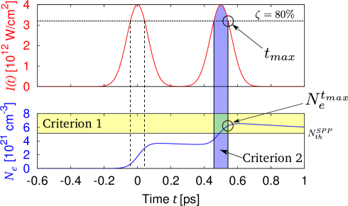
Two criteria must be satisfied to allow the excitation of Surface Plasmon Polaritons (SPPs). Criterion 1 is defined by the condition that carrier density must exceed a threshold density defined by Eq. (1). Combining Eqs. (1) and (2), this threshold density can be rewritten as Martsinovskii2008
| (7) |
Criterion 2 is based on the idea that temporal interference between the incident laser wave and the SPP is required (which occurs lastly during the second part of the double-pulse). This defines the last instant where the intensity of the second pulse drops to a fraction of its maximum value []. Both criteria are illustrated in Fig. 1 where the intensity distribution of the double-pulse sequence is shown in the upper part, and the corresponding carrier dynamics is presented in the lower part. is exemplified for a value of , and the corresponding is indicated by the two circles.
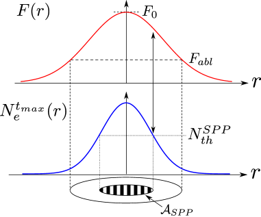
In order to consider the spatially Gaussian beam profile used in the experiments Hoehm2013 , the corresponding radial distribution of the carrier density has to be calculated. For that, the Eqs. (3-5) have been simultaneously solved numerically for different fluences and delays. The radial position of the Gaussian beam is linked to the local laser fluence by the relation . Thus, the radial position can be associated with . Applying now the threshold criterion (Eq. 7) allows to quantify the SPP active area , as illustrated in Fig. 2. By systematically varying for the given experimental conditions, a comparison between the SPP active area and the LSFL-rippled area can be performed as discussed in the following section.
3 Results
In order to quantify the impact of the optical absorption, Auger recombination and carrier diffusion, all of these processes have been studied individually. For each case, starting from the optimum agreement demonstrated in Ref. Derrien2013a , the corresponding process parameter (two-photon absorption: , Auger recombination: , carrier diffusion: ) has been varied while keeping the others unchanged.
Fig. 3 shows the SPP active area as a function of the double-pulse delay up to ps for three different values of two-photon absorption coefficient , and cm/GW. The results of the numerical calculations are shown as lines, while the LSFL rippled area is added as blue data points for comparison. The black solid line represents the optimum agreement between and . For (i.e., one-photon absorption only), the results do not reproduce the rapid decay of LSFL-rippled area at short pulse delays. Moreover, to obtain an optimum agreement with at longer delays, the peak fluence had to be set to J/cm2, which is 10 times higher than the experimental value J/cm2 Hoehm2013 . In order to quantify the importance of the two-photon absorption, has been varied between the two most prominent values found in the literature, i.e., cm/GW Bristow2007 and cm/GW Sabbah2002 . However, no signficant differences can be observed when the peak fluence is adjusted individually for an optimum agreement ( J/cm2 for cm/GW and J/cm2 for cm/GW). The choice of the latter is more reasonable here as its corresponding fluence is closer to the experimental value. These results demonstrate that the two-photon absorption is essential to explain the rapid decay of .

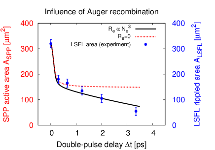
In order to quantify the impact of Auger recombination, the Auger recombination rate has been set to . Fig. 4 shows the SPP active area as a function of the double-pulse delay with (solid line) and without (dotted line) Auger recombination. For and temporally non-overlapping double-pulses, the SPP active area remains almost constant, indicating that diffusion cannot significantly reduce the laser-induced carrier density on a timescale of a few ps. The case with Auger recombination included () clearly demonstrates the major contribution of this effect to the SPP active area.
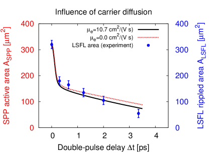
In order to study the effect of carrier diffusion, the carrier mobility was varied. Fig. 5 shows the SPP active area as a function of the double-pulse delay for two different carrier mobilities . The best agreement (black curve) with has been obtained by setting cm Derrien2013a , resulting from the carrier collision time fs reported in Ref. Sokolowski-Tinten2000 . The dotted curve has been calculated by setting . This comparison demonstrates the limited influence of carrier diffusion on SPP active area on the timescale up to a few ps.
4 Conclusion
The carrier dynamics at the surface of silicon upon femtosecond double-laser pulse irradiation has been numerically investigated as a function of double-pulse delay and laser peak fluence, considering different processes of carrier generation and relaxation. Based on that and on two optical criteria, the SPP active area was quantified. The comparison to experimental results of the LSFL rippled area confirms the SPP-based mechanism of LSFL formation. It was quantitatively demonstrated that the two-photon absorption is responsible for the fast decay in the sub-picosecond delay range of the SPP active area, while Auger recombination accounts for the slower area decay at delays up to several picoseconds. Diffusion plays a minor role only.
Acknowledgements.
T.J.-Y.D. acknowledges a postdoctoral fellowship awarded by the Adolf-Martens-Fond e.V. This work was supported by the German Science Foundation (DFG) under Grant Nos. RO 2074/7-2 and KR 3638/1-2.References
- (1) A. Borowiec, H.K. Haugen, Appl. Phys. Lett. 82(25), 4462 (2003)
- (2) M. Huang, F. Zhao, Y. Cheng, N. Xu, Z. Xu, ACS Nano 3(12), 4062 (2009)
- (3) U. Chakravarty, R. Ganeev, P. Naik, J. Chakera, M. Babu, P. Gupta, J. Appl. Phys. 109, 084347 (2011)
- (4) J. Bonse, J. Krüger, S. Höhm, A. Rosenfeld, J. Laser Appl. 24(4), 042006 (2012)
- (5) J.E. Sipe, J.F. Young, J. Preston, H.V. Driel, Phys. Rev. B 27(2), 1141 (1983)
- (6) A.M. Bonch-Bruevich, M.N. Libenson, V.S. Makin, V.A. Trubaev, Opt. Eng. 31(4), 718 (1992)
- (7) J. Bonse, S. Baudach, J. Krüger, W. Kautek, M. Lenzner, Appl. Phys. A 74, 19 (2002)
- (8) F. Costache, S. Kouteva-Arguirova, J. Reif, Appl. Phys. A 79, 1429 (2004)
- (9) M. Guillermin, F. Garrelie, N. Sanner, E. Audouard, H. Soder, Appl. Surf. Sci. 253, 8075 (2007)
- (10) J. Bonse, A. Rosenfeld, J. Krüger, J. Appl. Phys. 106, 104910 (2009)
- (11) J. Bonse, J. Krüger, J. Appl. Phys. 108, 034903 (2010)
- (12) T.J.Y. Derrien, T.E. Itina, R. Torres, T. Sarnet, M. Sentis, J. Appl. Phys. 114, 083104 (2013)
- (13) G.A. Martsinovskii, G.D. Shandybina, D.S. Smirnov, S.V. Zabotnov, L.A. Golovan, V.Y. Timoshenko, P.K. Kashkarov, Opt. Spectrosc. 105, 67 (2008)
- (14) T.J.Y. Derrien, T. Sarnet, M. Sentis, T.E. Itina, J. Optoelectron. Adv. Mater. 12(3), 610 (2010)
- (15) M. Barberoglou, G. Tsibidis, D. Gray, E. Magoulakis, C. Fotakis, E. Stratakis, P. Loukakos, Appl. Phys. A 113, 273 (2013)
- (16) S. Höhm, A. Rosenfeld, J. Krüger, J. Bonse, Appl. Surf. Sci. 278, 7 (2013)
- (17) S. Höhm, M. Rohloff, A. Rosenfeld, J. Krüger, J. Bonse, Appl. Phys. A 110, 553 (2013)
- (18) T.J.Y. Derrien, J. Krüger, T.E. Itina, S. Höhm, A. Rosenfeld, J. Bonse, Opt. Express (Accepted) (2013)
- (19) H. Raether, Surface Plasmons on Smooth and Rough Surfaces and on Gratings (Springer-Verlag, 1986)
- (20) K. Sokolowski-Tinten, D. von der Linde, Phys. Rev. B 61, 2643 (2000)
- (21) D. Bäuerle, Laser Processing and Chemistry, 4th edn. (Springer-Verlag, 2011)
- (22) E.D. Palik, Handbook of Optical Constants of Solids (Academic Press, 1985)
- (23) A. Sabbah, D. Riffe, Phys. Rev. B 66, 165217 (2002)
- (24) H.V. Driel, Phys. Rev. B 35(15), 8166 (1987)
- (25) E.J. Yoffa, Phys. Rev. B 21(6), 2415 (1980)
- (26) T. Sjodin, H. Petek, H.L. Dai, Phys. Rev. Lett. 81(25), 5664 (1998)
- (27) N.M. Bulgakova, R. Stoian, A. Rosenfeld, Quantum Electron. 40(11), 966 (2010)
- (28) N.M. Bulgakova, R. Stoian, A. Rosenfeld, I.V. Hertel, W. Marine, E.E.B. Campbell, Appl. Phys. A 81, 345 (2005)
- (29) A.D. Bristow, N. Rotenberg, H.M.V. Driel, Appl. Phys. Lett. 90, 191104 (2007)