The TTC 2013 Flowgraphs Case
Abstract
This case for the Transformation Tool Contest 2013 is about evaluating the scope and usability of transformation languages and tools for a set of four tasks requiring very different capabilities. One task deals with typical model-to-model transformation problem, there’s a model-to-text problem, there are two in-place transformation problems, and finally there’s a task dealing with validation of models resulting from the transformations.
The tasks build upon each other, but the transformation case project also provides all intermediate models, thus making it possible to skip tasks that are not suited for a particular tool, or for parallelizing the work among members of participating teams.
1 Objective of the Case
The objective of this case111This case’s project on github: https://github.com/tsdh/ttc-2013-flowgraphs-case is to evaluate the flexibility of transformation tools, i.e., to evaluate their usefulness for tasks requiring different capabilities. Although different capabilities are needed, all tasks are connected by their general topic: analysis and transformations in compiler construction.
Task 1 deals with a typical model-to-model transformation problem. Given an abstract syntax graph of a Java program conforming to a very detailed metamodel, the structure graph of the original program conforming to a much simpler metamodel has to be generated. Embedded in this task is a model-to-text transformation where parts of the Java syntax graph have to be serialized back to Java source code.
In task 2, the structure graph resulting from task 1 should be enhanced with control flow information. This is an in-place transformation task which is suited for graph transformation tools but can also be tackled algorithmically.
Task 3 is also an in-place transformation. Based on the control flow graph resulting from task 2, data flow information has to be synthesized. Again, this task is suited to be tackled with graph transformations or algorithmically.
The context of task 4 is a bit offside the strict transformation context. A simple validation tool and DSL should be developed to offload testing to Java developers.
Because every task builds upon the results of previous tasks, the intermediate models are also provided to allow participants to defer or skip tasks not particulary suited for their tools, or to allow teams for developing solutions in parallel.
2 Detailed Task Description
Task 1: Structure Graph.
The first task requires writing a model-to-model transformation. The source
models are abstract Java syntax graphs conforming to the JaMoPP metamodel
[4]. The JaMoPP metamodel covers the complete syntax of Java 7.
However, to restrict the size of the transformation, the elements actually
contained in the provided source models is limited. They all contain one
compilation unit containing exactly one class with exactly one method. The
method may have parameters. In the method’s body, there may be local variable
declarations, arithmetic expressions (only +, -, *, and
/), assignments, unary modification expressions (i++; and
i--;), return statements, and blocks. There may be
if-statements and while-loops with a boolean expression as
condition. Statements may be labeled, and break/continue may be
used with or without target label. The target metamodel of the transformation
is depicted in Figure 1.
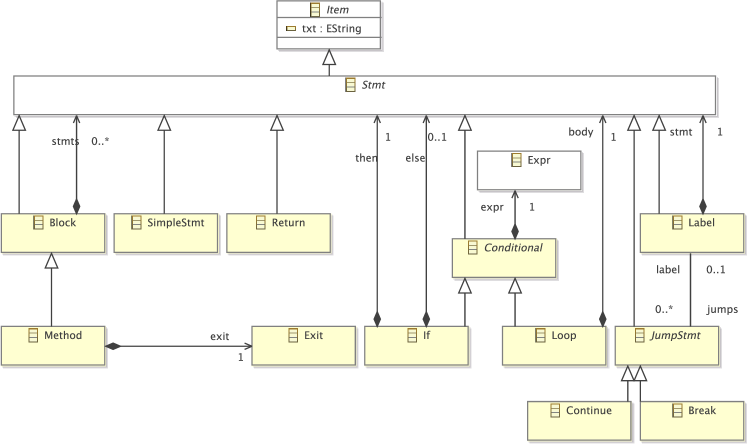
It is very similar to the original JaMoPP metamodel from a structural point of
view. The major difference is that statements and expressions are represented
as one single object instead of being split up any further. Another difference
is that every Method has exactly one Exit. There is no
correspondence in Java, but it’s a synthetic element added in favour of task 2.
No matter how a method is exited, the last object in a method’s control flow
graph is this method’s Exit object.
All metamodel classes extend the abstract Item class, even the class
Expr although not visible in Figure 1.
Item declares a txt attribute. The transformation has to set the
value of this attribute to the concrete Java syntax of the statement or
expression, that is, there is a model-to-text transformation embedded in this
model-to-model transformation.
With the exception of Break and Continue objects that might refer
to a target Label, the structure graphs created by the transformation
are simple trees that reflect the containment hierarchy of the method.
Task 2: Control Flow Graph.
This task deals with an in-place transformation problem. The semantics of the Java programming language should be integrated into the structure graphs created by the previous transformation. The task is to perform an intra-procedural control flow analysis. Any instruction should be connected to the instructions that may follow it in the method’s control flow. Figure 2 shows the relevant metamodel excerpt.
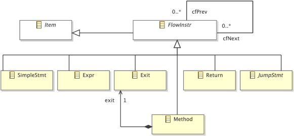
Simple statements, expressions, the synthetical exits, methods, return,
and the jump statements break and continue extend
FlowInstr. Every flow instruction knows its immediate control flow
predecessors (cfPrev) and successors (cfNext). It’s those links
the transformation has to synthesize from the structure graph.
Blocks, labels, loops, and if-statements don’t participate in the control flow. Instead, when control flow reaches a block, the first flow instruction in the block is the control flow successor of the previous flow instruction. Since blocks may be nested in other blocks, the first flow instruction is actually the first one reachable by a depth-first search. These first semantics apply to the whole description of this task.
In case of a label, the first flow instruction in the labled statement is the control flow successor.
In case of loops and if-statements, the successor is their test expression. This expression has in turn two control flow successors. If it is a test expression of a loop, the successors are the first flow instruction in the loop’s body, and the first flow instruction following the loop. If it is a test expression of an if-statements, the first successor is the first flow instruction in then-statement. If there is an else-statement, its first flow instruction is the other control flow successor. Otherwise, the other successor is the first flow instruction in the statement following the if-statement.
The control flow successor of a Method is its first flow instruction,
and Return statements always have the method’s Exit as control
flow successor.
The most complex control flow rules apply to the Break and
Continue statements. Without a target label, the control flow successor
of a Break is the first flow instruction following the immediately
surrounding loop, and the successor of a Continue is the test expression
of the immediately surrounding loop. With a target label, the control flow
successor of a Break is the first flow instruction following the labeled
statement, and the successor of a Continue is the expression of the
surrounding labeled loop.
Task 3: Data Flow Graph.
In this task, an intra-procedural data flow analysis should be performed. The relevant metamodel excerpt is shown in Figure 3. This can be done based on the control flow graph, but one important piece of information is missing from it: for every flow instruction, the sets of read and written variables have to be known. Therefore, this task is twofold:
-
1.
The model-to-model transformation from task 1 has to be extended so that it also creates
Varobjects for local variables andParamobjects for method parameters which are connected to flow instructions reading from and writing to them. -
2.
A transformation synthesizing data flow edges has to be written that takes the control flow graph resulting from applying task 2’s transformation to the result of the extended java-to-structure-graph transformation.
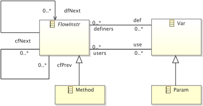
Subtask 3.1.
For every local variable statement and every method parameter in the JaMoPP
model, the extended model-to-model transformation has to create a Var or
a Param object, respectively. The txt attribute should be set to
the variable’s/parameter’s name. Furthermore, every flow instruction should be
connected to the variables it writes (the def reference) and to the
variables it reads (the use reference).
Subtask 3.2.
The model resulting from applying the enhanced model-to-model transformation on the JaMoPP syntax graphs followed by applying the control flow transformation from task 2 to it is the source model for the data flow transformation to be developed in this subtask.
It’s sole purpose is to synthesize dfNext links. For every flow
instruction , a dfNext link has to be created from all nearest
control flow predecessors that define a variable which is used by .
Formally:
That is, uses at least one variable defined by , and there is a control flow path from to in which at least one variable used by and defined by is not redefined by intermediate flow instructions.
There are several ways to tackle this problem. A simple one is to take the definition literally, i.e., for every flow instruction search the nearest control flow predecessors that define a variable used by instruction with quadratic worst-case effort. A more efficient and sophisticated algorithm is described in the dragonbook [2], chapter 9.1. The models resulting from this task which include control and data flow information are called program dependence graphs (PDG), and they play an important role in the optimization phase in compilers [3].
Task 4: Validation.
The fourth task is no strict transformation task. Instead, the challenge is
validating the program dependence graphs resulting from task 3. Concretely, it
should be checked if all cfNext and dfNext links are set
properly.
A simple tool that gets a result PDG as input and all control and data flow links specified with a simple DSL should be provided. The tool should print all missing and all false links, i.e., all links defined in the textual specification that don’t occur in the model, and all links occuring in the model that are not defined by the specification.
In the example Java programs provided in this case description project, every
statement and expressions occurs at most once in a method, e.g., there’s is no
method with two i++; statements. Therefore, for all PDGs generated from
them, the txt attribute can be used to uniquely identify any object.
An example specification is given in Listing 1. There’s no restrictions on the actual syntax except that it should be easy to write for a Java programmer.
The requested tools’s job is simple. It has to load a PDG and to read a
specification such as depicted in Listing 1. For
any cfNext or dfNext link in the model, it has to check if it is
also defined in the specification. If not, it has to print a false-link
warning message. Reversely, it has to check if every link defined in the
specification also occurs in the model. If not, it has to print a
missing-link warning.
3 Evaluation
The evaluation of solutions has been done in two phases. Before the workshop, there was an open peer review where participants assessed the objective criteria completeness, correctness, and efficiency. Furthermore, they assigned scores for the subjective criteria of the transformation language’s and tool’s usefulness and its ease of use. During the workshop, all attendants only assigned scores for the subjective criteria. The overall winner (the Epsilon solution) was then determined by setting the open peer review scores off against the workshop scores.
References
- [1]
- [2] Alfred V. Aho, Monica S. Lam, Ravi Sethi & Jeffrey D. Ullman (2006): Compilers: Principles, Techniques, and Tools (2nd Edition). Addison-Wesley Longman Publishing Co., Inc., Boston, MA, USA.
- [3] Jeanne Ferrante, Karl J. Ottenstein & Joe D. Warren (1987): The program dependence graph and its use in optimization. ACM Trans. Program. Lang. Syst. 9(3), pp. 319–349, 10.1145/24039.24041.
- [4] Florian Heidenreich, Jendrik Johannes, Mirko Seifert & Christian Wende (2009): JaMoPP: The Java Model Parser and Printer. Technical Report TUD-FI09-10, Technische Universität Dresden, Fakultät Informatik. ftp://ftp.inf.tu-dresden.de/pub/berichte/tud09-10.pdf.