Double scouring by turbulent jets downstream of a submerged sluice gate
Abstract
In this work we study the scour produced by a jet downstream of a submerged sluice gate on a non-cohesive particles sediment bed. The experiments were performed for various values of sill heights and fluid depths. New regimes were observed in which two holes are simultaneously developed. We identified the origins of the two holes and showed that they are produced by different scouring mechanisms. The dependence of the position of the holes with the approach fluid depth and the gate opening were studied and expressed in terms of adequate non-dimensional numbers.
Keywords: Scour, Jet flow, Turbulent flow
1 Introduction
The interaction between a moving fluid and a sediment bed is a problem of great interest due to the physical processes that are involved, as well as for its relevance in engineering applications. The scouring that takes place in the vicinity of hydraulic structures is particularly interesting, owing that the erosion can compromise the safety of such devices. The behavior of the scouring produced by a jet that emerges downstream of a sluice gate has been studied in a series of works( Rajaratnam, 1981 , Chaterjee et al.,1994, Hogg et al.,1997, Bey et al.,1997, Balachandar et al.,2000).
These studies showed that at an initial stage the scour develops rapidly but as time goes the erosion enters in a stage in which the bedform changes very slowly. The details of this evolution depend on flow field, the geometry, and the characteristics of the grains. In some works it has been suggested that, at a given geometry, the profiles of the scour hole at different times are similar (Rajaratnam,1981). This topic has been controversial since the results obtained in other works do not support this behavior. Most of these cited works focused their investigations to study empirically the relation between the bedform, the flow and the properties of the grains. Efforts to predict the profile of the eroded bed from first principles have been limited, with the exception of the works of Hogg et al.(1997) and Hill and Younkin (2009). In spite of the advances that have been accomplished about the relation between the erosion and the transport of sediments, the basic mechanism of scouring is still not fully understood, due to the complex nature of the flow fields (Hogg et al.,1997, Bey et al.,1997). It is thus of interest the investigation of this subject considering the different ways in which the erosion can take place. In the present work we study the evolution of a bed of non-cohesive particles downstream of a submerged sluice gate. We obtained different regimes in which two scouring holes produced by distinct mechanisms are observed. We investigated the origin of these bedform changes and the interactions between the bed and the flow. The work is organized as follows: In section 2 we describe the experimental setup. In section 3 the experimental results are presented, describing the holes characteristics and their dependence with the parameters of the flow. In section 4 we study the structure of the flow and the origin of the scour. In section 5 the results are discussed and in section 6 we give a summary of the work.
2 Experimental setup
The experimental work was performed in a recirculating open channel of 3 m long, 0.19 m wide, and 0.3 m of maximum height. With the use of a pump, the fluid was withdrawn from a discharge tank and conducted to a provision tank, from where the fluid enters in the channel. The caudal discharged was measured with a flowmeter, and was maintained constant (with the help of a globe valve) at the value = 1 l/s in all the experiments. In order to reduce the turbulence level, the discharge in the provision tank was performed at its bottom. In addition, a flow disperser and grids were implemented to reduce the kinematical energy of the flow. A gate located at the end of the channel was used to control the water depth. The fluid depth upstream the gate was taken between 3.0 and 5.0 cm. The inclination of the channel is variable. It is adjusted in order to maintain constant the water depth along the channel. At the entrance of the channel a device to destroy larger vortices was placed. Also, just before the gate at the end of the channel, a gap is arranged on the floor of the channel to reduce the impact of the gate upstream. In the studied area, in the center of the channel, variation of velocity with height was analyzed for a rigid flat bed without sediment. It was observed that the flow was developed and it obeys the wall law. The sketch of the experimental arrangement is given in Fig. 1. A cohesive particles bed, 2.2 cm deep, was placed at the whole length of the channel floor. The particles were glass spheres with diameter between 420 and 840 m, with an averaged diameter = 630 m. A sluice gate of variable opening was installed in the middle of the channel. The opening of the gate was varied between 19 mm and 24 mm over the particle bed. The flow field was visualized using different procedures as PIV (Particle Image Velocimetry), and ink injection. In the case of PIV, polyamide particles with 50 m diameter were used. A laser (500 mW) and spherical lens were used to create a light sheet of 1 mm thick. To optimize the PIV, the glass spheres were stained in black. This avoided the reflection of the laser light from the spheres, which improves the quality of the images and PIV measurements.
3 Experiments
3.1 Scour profiles
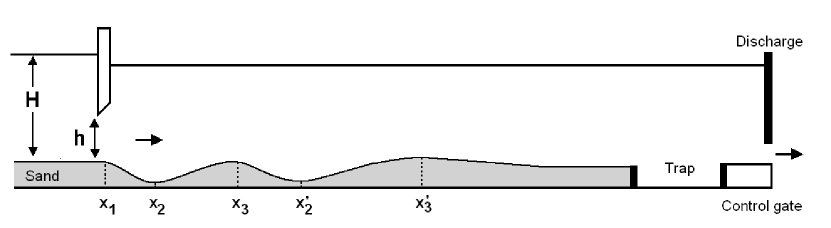
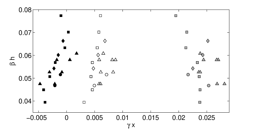
In our experiments, the sand bed extends at both sides of the gate. As a consequence, the scour can begin upstream of the gate. Contrary to what is usually observed, two holes of different origin were found to occur. In the schematic of Fig. 1 we define parameters that determine the position of the first and second holes. Here, the represent the following positions: beginning of the first hole, position at which the first hole achieved the maximum depth, end of the first hole, beginning of the second hole, maximum depth of the second hole, end of the second hole. We note that the end of the first hole coincides with the beginning of the second, i.e. . All these positions are measured from the localization of the sluice gate. We also define and , which represent the depths of the first and second holes respectively. In the present experiments, the profiles did not reach an steady regime. We began the experiments with a flat bed sand and they were carried out during a period of 10 minutes. After this, the position and depths of the holes were measured. These data are those shown in Figs. 2-5.
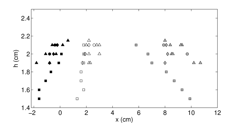
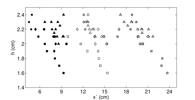
It can be seen from the Figs. 2 and 3 that the dependence of the positions with the opening are very different for the two holes. In the case of the first hole, values tend to remain constant; the length of the hole , for the same depth value , increases for smaller values of the gate openings (Fig. 2); and the same applies to the depth (Fig. 4). On the other hand, the second hole moves downstream when is smaller, remaining practically constant the length of the hole (Fig. 3). Moreover, the depth also has a different behavior. For a same depth value , lower gate heights generate deeper holes until a threshold value, from which lower value of generate holes less deeper (Fig. 4). As will be discussed in section 4, this phenomenon is caused by the influence of the first hole on the second one.
3.2 Nondimensional numbers
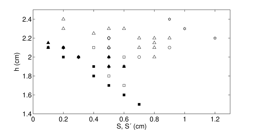
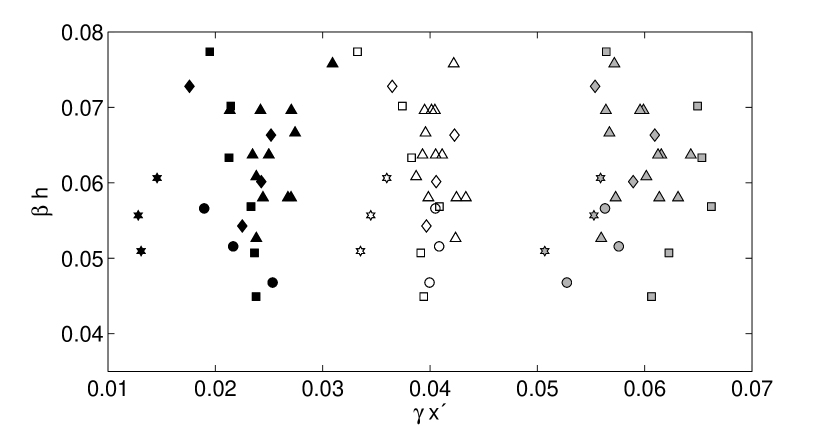
In order to gain clarity concerning the relation of the holes positions with and , we attempted to construct non-dimensional numbers which could capture this dependence in a simpler manner. We considered different ways to define quantities having dimensions of length, in order to non-dimensionalize the distances. The best results were achieved with the quantities and , where is the width of the channel. In principle, the quantity is unimportant to determine the flow, but it was included to get the correct dimensions. In Figs. 5 and 6 the dimensionless positions of the two holes , for different values of are shown. It can be seen that the non-dimensional positions fall fairly well on curves of smooth variation.
3.3 Flow structure
The first hole has similar characteristics to the scour profile that is usually observed downstream of submerged gates. This scouring is mainly driven by the jet that emerges from the gate, which is attached to the sediment bed. It is currently accepted that erosion takes place when the shear stress of the jet flow exerted on the sediment surface exceed a critical value which depends on the characteristic of the particles. In wall jets, it is typically observed that the erosion decreases downstream of the gate with the distance due to the reduction of the jet velocity (Hogg et al.,1997). Thus it is intriguing that the second hole develops at positions where the shear of the jet should not be sufficient for bed mobilization. We hypothesized that the process that cause the second hole originates in the loss of the jet stability and the subsequent turbulence development. The stability of a jet attached to a wall has been studied in many works ( Chun and Schwarz (1967), Bajura and Szewczyk (1970), Levin et al. (2005)) . These studies showed that when the Reynolds number is larger than a critical value, the jet becomes unstable and the flow undergoes a transition to turbulence.
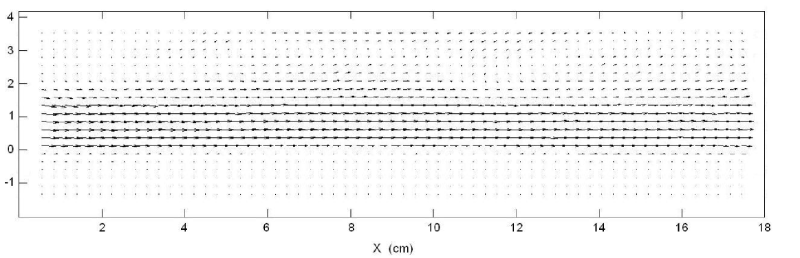
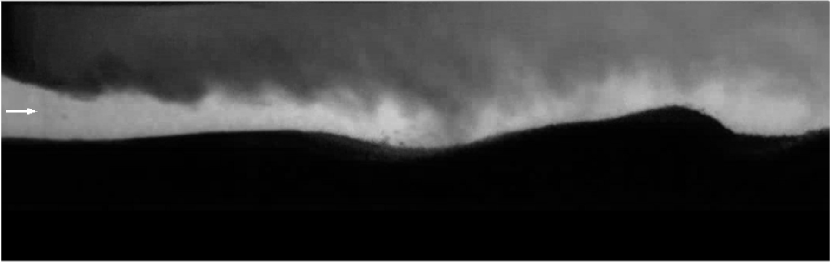
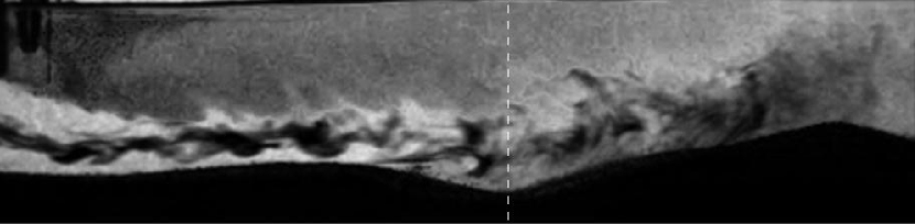
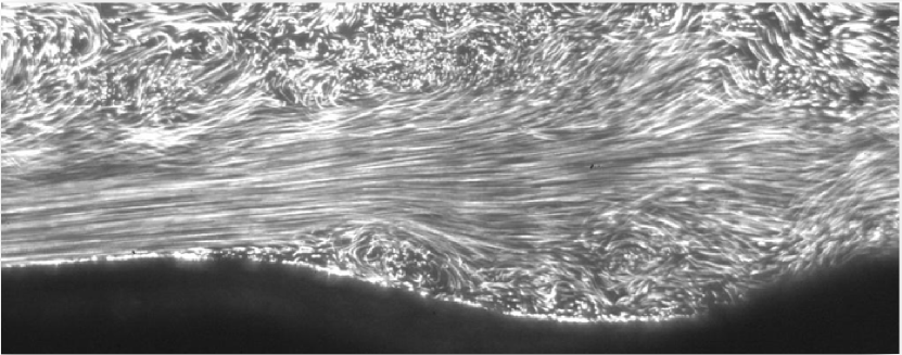
In order to test this hypothesis, we implemented PIV measurements and visualization by ink injection. In Fig. 7 the flow field for cm, cm is presented, where the presence of the jet is clearly seen. In Figs. 8 and 9 are shown the images corresponding to experiments including fluid colored with ink. From these figures, it is clearly seen that the region where there is strong mixing produced by the turbulence, coincides with the position of the second hole. The jet instability and the formation of vortices can be observed in Fig. 10, which show the path lines of the particles. These images support the view that it is the turbulence developed after the destabilization of the jet that originates the second hole. When the jet is separated from the sand bed, vortices are formed between them. These vortices are shed quasi-periodically and travel downstream. The dynamics is similar to the one oberved in flows behind obstacles (Cabeza et al., 2009).
Turbulent flow is not required to develop scouring, but turbulence increases erosion greatly (Zanke, 2003). This is the reason why the second hole is developed at a position where the laminar flow could not produce bed displacement.
4 Discusion
The results about the flow structure show that the second hole formation is related with the turbulence that develops after the jet destabilization. When turbulence reaches the bed, strong scouring takes place. We observed that this effect depends on the evolution stage of the first hole. When the first hole is not still well developed, the scouring at the position where the second hole will appear is very weak. When the first hole begins to form, the turbulent fluctuations at the bed surface become significant and the depth of the second hole starts to grow. This is probably due to the fact that the presence of the dune that limits the first hole enhances the flow separation and the instability of the jet. It is known that the wall exerts an stabilizing effect on the jet flow. Thus, the formation of the second hole, is favored with the existence of the first one. This is true if the rate growing of the first hole is not too large. If the first hole forms too fast, the dune that forms downstream the first hole alters the flow in a manner that the second hole is inhibited. This situation is reached when the value of is small. This tendency is reflected in Fig. 4. While the larger values of the first hole depths are obtained with the lowest values of , the larger values of correspond to intermediate values of . We notice that the formation of the first hole is produced by the shear stress of the jet flow and thus is not related to flow destabilization.
5 Conclusions
In this work we have studied the erosion produced by a turbulent jet downstream of a sluice gate on noncohesive particles sediment bed. We found new regimes in which two types of holes, clearly distinguishable, are observed to develop. As the experimental results shown, the two holes are caused by distinct mechanisms.
The formation of the first hole is caused by the shear stress of the jet flow and corresponds to the one usually observed in eroded beds downstream gates. Then, the formation of the first hole can be understood considering a laminar or a weak turbulence flow.
On the other hand, the second hole is driven by turbulent fluctuations that stem from jet flow destabilization. Since turbulence increases scouring greatly, the second hole is developed at locations where the laminar or weakly turbulent flow could not produce bed displacement. However, in spite of the fact that the holes originate from different mechanisms, the second hole development depends on the first hole profile. The rate formation of the second hole is maximized for a medium value of the first hole depth . If is too large, the second hole is inhibited. This implies that the maximum depth of the second hole takes place for an intermediate value of the to ratio. In these conditions, the depth of the second hole can be larger than those of the first hole. As a consequence, the second hole is at least so important as is the first one. Thus its study is of interest and deserves further investigation. We found nondimensional numbers for which the experimental data concerning the positions of the holes and the ratio result ordered in a simple way.
Acknowledgements
This research was supported by CSIC and PEDECIBA, Uruguay.
References
Bajura, R., Szewczyk, A. (1970). Experimental investigation of a laminar two-dimensional plane wall jet. Phys. Fluids. 13, 16531664.
Balachandar, R., Kells, J., Thiessen, R. (2000). The effect of tailwater depth on the dynamics of local scour. Can. J. Civ. Eng.. 27 1, 138150.
Bey, A., Faruque, M., Baladanchar, R. (2007). Two-dimensional scour hole problem: role of fluid structures. J. Hydraul. Eng.. 133 4, 414430.
Cecilia Cabeza, Juan Varela, Italo Bove, Daniel Freire, Arturo C. Martí, L. G. Sarasua, Gabriel Usera, Raul Montagne, and Moacyr Araujo (2009). Two-layer stratified flows over pronounced obstacles at low-to-intermediate Froude numbers. Phys. Fluids 21, 044102 .
Chatterjee, S., Ghosh, S., Chatterje, M. (1994). Local scour due to submerged horizontal jet. J. Hydraul. Eng.. 120 8, 973992.
Chun, D., Schwarz, W. (1967). Stability of the plane incompressible viscous wall jet subjected to small disturbances. Phys. Fluids. 10, 911915.
D.F. Hill and B.D. Younkin (2009). A simple estimation of the growth rate and equilibrium size of bedforms created by a turbulent wall jet. J. Hydraul. Res. 47, (2009), 619625.
Hogg, A., Huppert, H., Dade, W. (1997). Erosion by planar turbulent jets. J. Fluid. Mech.. 338, 317340, and references therein.
Levin, O., Chernoray, V., Lofdahl, L.,Henningson, D. (2005). A study of the Blasius wall jet. J. Fluid Mech.. 539, 313347.
Rajaratnam, N. (1981). Erosion by plane turbulent jets. J. Hydraul. Res. 19 4, 339358.
Zanke, U. (2003). The influence of turbulence on the initiation of sediment motion. International Journal of Sediment Research. 1 18, 1731.