A Nitsche-based cut finite element method for a fluid–structure interaction problem
Abstract.
We present a new composite mesh finite element method for
fluid–structure interaction problems. The method is based on
surrounding the structure by a boundary-fitted fluid mesh which is
embedded into a fixed background fluid mesh. The embedding allows
for an arbitrary overlap of the fluid meshes. The coupling between
the embedded and background fluid meshes is enforced using a
stabilized Nitsche formulation which allows us to establish
stability and optimal order a priori error estimates,
see [45]. We consider here a steady state
fluid–structure interaction problem where a hyperelastic structure
interacts with a viscous fluid modeled by the Stokes equations. We
evaluate an iterative solution procedure based on splitting and
present three-dimensional numerical examples.
KEY WORDS. Fluid–structure interaction, cut
finite element method, embedded meshes,
stabilized finite element methods, Nitsche’s method
1. Introduction
In fluid–structure interaction applications, the underlying geometry of the computational domain may change significantly due to displacement of the structure. In order to deal with this situation in a standard setting with conforming elements, a mesh motion algorithm must be used. If the displacements are significant, the deformation of the mesh may lead to deteriorating mesh quality which may ultimately require re-meshing of the computational domain. Alternative, more flexible, techniques are therefore of significant practical interest.
In this paper, we consider a combination of standard moving meshes and so-called CutFEM technology [14]. Essentially, the structure or elastic solid is first embedded into a boundary-fitted fluid mesh which moves along with the deformation of the solid to keep the fluid–structure interface intact. The motion of the fluid mesh surrounding the structure is obtained by solving an elasticity problem with given displacement at the fluid–structure interface. The boundary-fitted fluid mesh is then embedded into a fixed background mesh where we allow for an arbitrary overlap of the fluid meshes in order to facilitate the repositioning of the moving fluid mesh within the fixed background mesh. The fluid is then discretized on both the moving overlapping domain, using an Arbitrary-Lagrange-Eulerian (ALE) type approach[19, 20], and on the fixed background mesh, using a standard discretization posed in an Eulerian frame.
The coupling at the fluid–fluid interface between the overlapping and underlying fluid meshes is handled using a stabilized Nitsche method developed for the Stokes problem in [45]. The stabilization is constructed in such a way that the resulting scheme is inf-sup stable and the resulting stiffness matrix is well-conditioned independent of the position of the overlapping fluid mesh relative to the fixed background fluid mesh. As a result, optimal order error estimates are also established. In order to deal with the cut elements arising at the interface, we compute the polyhedra resulting from the intersections between the overlapping and background meshes. These polyhedra may then be described using a partition into tetrahedra; this partition may in turn be used to perform numerical quadrature. We refer to [44] for a detailed discussion of the implementation aspects of cut element techniques in three spatial dimensions. We remark that Nitsche-based formulations for Stokes boundary and interface problems where the surface in question is described independently of a single, fixed background mesh were proposed in [13, 46, 29, 15]. A Nitsche-based composite mesh method was first introduced for elliptic problems in [27].
One may also consider formulations, where the structure is described via its moving boundary which is immersed into a fixed background fluid mesh. Prominent examples are Cartesian grid methods, e.g. [47], the classical immersed boundary method introduced by Peskin [50, 49], its finite element pendant proposed in [12, 60, 61], formulations based on Lagrange multipliers, cf. [60, 59, 24, 25, 51] and on Nitsche’s method [28]. However, the use of an additional boundary-fitted fluid mesh as in the current work is attractive since it allows for the resolution of boundary layers and computation of accurate boundary stresses. Often, the construction of the surrounding fluid mesh can easily be generated by extending the boundary mesh in the normal direction. We plan to further investigate the properties of the fluid–structure coupling in future work.
As our proposed scheme combines an ALE-based discretization on the fluid mesh surrounding the structure with an Eulerian-based discretization on the fixed background fluid mesh, it can be classified as hybrid Eulerian-ALE or Chimera approach. Such hybrid schemes are built upon the concept of overlapping meshes introduced for finite differences and finite volume schemes in the early works of Volkov [56], Starius [53, 54], Steger et al. [55] and later by Chesshire and Henshaw [17] and Aftosmis et al. [3], where the primary concern was to ease the burden of mesh generation by composing individually meshed, static geometries. The idea of gluing meshes together was then explored for finite element methods by Cebral and Löhner [16], Löhner et al. [41, 42] to study the flow around independently meshed complex objects such as cars, collection of buildings or stents in aortic vessels. In these works, relatively simple interpolation schemes were used to communicate the solution between overlapping meshes. To achieve a physically more consistent coupling between the solution parts presented on different domains, Schwarz-type domain iteration schemes using Dirichlet/Neumann and Robin coupling on overlapping domains have been proposed for the Navier-Stokes equations in [31]. A completely different route was taken by Day and Bochev [18] who reformulated elliptic interface problems as suitable first-order systems augmented with least-square stabilizations to enforce the interface conditions between the mesh domains to be tied together.
Introducing special interpolation stencils close to the fluid–fluid interface, a finite volume based Chimera method for flow problems involving multiple moving rigid bodies was formulated in [58, 23] and [30], where higher-order Godunov fluxes where used. This method was then extended by Banks et al. [11] to deal with (linearly) elastic solids in two space dimensions, and thus represents an instance of a hybrid ALE-fixed grid method. This approach has barely been explored in the context of finite-element methods for fluid–structure interaction problems: Wall et al. [57] and later Shahmiri et al. [52] used interpolation between fluid meshes and extended finite element techniques to couple fluid–fluid meshes, Baiges and Codina [10] introduced an auxiliary ALE step to convect information on the fixed background mesh between two consecutive time-steps.
In contrast to these contributions, our method is based on a variational finite element approach that leads to a monolithic and physically consistent coupling between the overlapping and underlying fluid meshes, which eliminates the need of introducing inconsistent interpolation operators. In addition, opposed to similar finite element based approaches presented e.g. in [57, 52], our scheme used for the fluid problem is proven stable and optimally convergent, even for higher-order elements, independent of the location of the interface as shown in [45]. Thus, the new scheme for the fluid–structure interaction problem proposed in this work exhibits the necessary robustness that is essential for developing reliable hybrid ALE-fixed mesh methods.
In the current work, we consider the steady state deformation of a hyperelastic solid immersed into a viscous fluid governed by the Stokes equations. We solve for the steady state solution using a fixed point iteration where in each iteration the fluid, solid, and mesh motion problems are solved sequentially. We present two numerical examples in three dimensions, including one example with a manufactured reference solution.
The outline of the remainder of this paper is as follows: in Section 2, we summarize the governing equations of the fluid–structure interaction (FSI) problem; in Section 3, we describe the overlapping mesh method; in Section 4, we present an algorithm for the solution of the stationary fluid–structure interaction model problem; in Section 5, we present three-dimensional numerical examples; before drawing some conclusions in Section 6.
2. A stationary fluid–structure interaction problem
We consider a fluid–structure interaction problem posed on a domain where is the domain occupied by the fluid and is the domain occupied by the solid. We assume that both and are open and bounded and that they are such that . Furthermore, we decompose the fluid domain into two disjoint subdomains , such that . Here, represents a part of the fluid domain surrounding the solid domain ; more precisely, we assume that . The fluid–structure interface is denoted by and the interface between the two fluid domains is denoted by . Here, the topological boundary for any given set is defined by where and denotes the closure and interior of , respectively. For simplicity, we assume that the fluid domain boundary consists of two disjoint parts: , and that the solid domain boundary decomposes in a similar manner: . This notation is summarized in Figure 2.1.

We assume that the fluid dynamics are governed by the Stokes equations of the following form: find the fluid velocity and the fluid pressure such that
| (2.1) | |||||
| (2.2) |
where is a given body force and is the fluid viscosity.
Next, we assume that the velocity is prescribed on both the fluid–structure interface and on the remainder of the fluid boundary:
| (2.3) | |||||
| (2.4) |
Moreover, we enforce the continuity of the fluid velocity and of the fluid “stress” on the fluid–fluid interface by the following conditions:
| (2.5) | |||||
| (2.6) |
Here denotes the jump in a function (or each component of a vector field) over the interface where denotes the restriction of to for . Furthermore, is the unit normal of directed from into .
Correspondingly, we assume that the structure deforms as an elastic solid satisfying the equations: find such that
| (2.7) |
where is the (Cauchy) stress tensor and is a given body force. The precise form of the Cauchy stress tensor will depend on the choice of the elastic constitutive relation. In later sections, we will consider both linearly elastic and hyperelastic constitutive equations relating the displacement to the stress. As boundary conditions, we assume that the displacement of the structure is given on part of the boundary and that the structure experiences a boundary traction on the fluid–structure interface:
| (2.8) | |||||
| (2.9) |
The coupling between the fluid and the structure problems requires the fluid and solid stresses and velocities to be in equilibrium at the interface . In the stationary case considered here, these kinematic and kinetic continuity conditions are taken care of by ensuring that (2.3) and
| (2.10) |
hold, where is the fluid stress tensor: and is the symmetric gradient .
3. An overlapping finite element discretization of the FSI problem
The nonlinear nature of the fluid–structure interaction problem (2.1)–(2.10) mandates a nonlinear solution scheme such as a Newton-type or fixed-point method. A classical and well-studied approach is to decompose the coupled problem into separate systems of equations via a Dirichlet–Neumann fixed-point iteration [48, 36, 35]. This is also the route taken here. Alternatively, more sophisticated iteration schemes based on a Robin-type reformulation of the interface conditions (2.3),(2.9), and (2.10) might be employed, see for instance [7, 9, 8]. The basic idea of the Dirichlet–Neumann fixed-point iteration is to start with solving the fluid problem (2.1)–(2.6) on a given starting domain. The resulting fluid boundary traction acting on the fluid–structure interface then serves as Neumann data for the structure problem (2.7)–(2.10). The structure deformation dictates a displacement of the fluid domain boundary, and in turn, a new configuration of the fluid domain. This sequence of steps is repeated until convergence.
Each of the three subproblems (the fluid problem, the structure problem and the domain deformation) will be solved numerically using separate finite element discretizations. Overall, we will employ an overlapping mesh method in which a fixed background mesh is used for part of the fluid domain and a moving mesh is used for the combination of the structure domain and its surrounding fluid domain. We note that methods based on overlapping meshes (as the one considered here) are sometimes also called Chimera methods. Before describing each of the discretizations, we here present an overview of the set-up of the computational domains.
For simplicity, we assume that the computational domain is fixed throughout the fixed-point iteration while the fluid and structure subdomains will be updated in each iteration step. In each step, we consider the following set-up, illustrated in Figure 3.1, of the computational domains. First, we assume that is tessellated by a background mesh . Second, we assume that the current representation of the subdomains and are tessellated by meshes and , respectively, and that these meshes match at their common interface. As a result, defines an admissible and conforming mesh of the combined domain . All meshes are assumed to be admissible and to consist of shape-regular simplices.


We further note that the background tessellation may be decomposed into three disjoint subsets:
| (3.1) |
Here are defined with reference to and denote the sets of elements in that are not, completely or partially overlapped by . More precisely, , and . In addition, we assume that is sufficiently fine near the fluid–fluid interface in the sense that for all . In other words, the elements in the fluid background mesh have to be small enough close to such that a single element does not stretch from the fluid–fluid interface to the fluid–structure interface. Next, we introduce the reduced background mesh , consisting of the elements in that are either not or only partially overlapped by , and associated domain :
| (3.2) |
Note that contains (but is generally larger than) . We further define the so-called fluid overlap region . In general, for each overlapping mesh configuration described by some (background) mesh and some overlapping domain, the procedure described above defines what we shall refer to as the reduced (background) mesh.
3.1. An overlapping mesh method for the fluid problem
In this section, we present a finite element discretization of (2.1)–(2.6) posed on a pair of overlapping meshes, first proposed in Massing et al. [45]. The pair of meshes consist of an overlapped mesh and an overlapping mesh: in our case the reduced background mesh plays the role of the overlapped mesh, while is the overlapping mesh.
For any given mesh , let be the space of continuous piecewise linear vector fields and let be the space of continuous piecewise linears, both defined relative to . We define the composite finite element spaces and for the overlapping fluid meshes by
| (3.3) |
Moreover, we denote by the subspace of that satisfies the boundary conditions (2.3)–(2.4) and by the corresponding homogeneous version. The overlapping mesh discretization of (2.1)–(2.6) then reads: find such that
| (3.4) |
where is defined for all and all by
| (3.5) |
and the forms , , and are given by
| (3.6) | ||||
| (3.7) | ||||
| (3.8) | ||||
| (3.9) |
for . Here and throughout, denotes the inner product over some domain , while denotes a convex combination with of across the interface . In particular, we choose in accordance with Hansbo et al. [27]. Finally, the linear form is defined by
| (3.10) |
for all and all .
A major strength of the employed scheme for the fluid problem is that the extension of the stabilization term (3.9) from the physical domain to the overlap region in combination with the least-square stabilization (3.8) results in a well-conditioned and optimally convergent scheme, independent of the location of the overlapping mesh with respect to the fixed background mesh. Thereby, typical difficulties arising from potentially small cut cells where for are completely eliminated. Consequently, for a continuous solution satisfying of (2.1)–(2.6) and a discrete solution satisfying (3.4), the following optimal error estimate holds independently of the fluid–fluid interface position [45]:
| (3.11) |
Here, is an appropriate version of the standard norm on accounting for the fluid overlap region ; see [45] for more details.
3.2. A finite element discretization of the structure problem
The structure problem is described by (2.7)–(2.9) in the current solid domain. As the current solid domain is actually unknown, a standard approach to discretizing such problems is to map the governing equations back to a fixed reference (Lagrangian) frame. We choose a reference domain with coordinates and denote the deformation map from the reference to the current solid domain by :
| (3.12) |
In general, the notation for all domains and quantities pulled back to the Lagrangian framework will be endowed with a ; for instance and denote the solid reference domain and solid displacement in the reference frame, respectively. In particular, .
In the Lagrangian frame, the problem reads: find the solid displacement such that
| (3.13) | |||||
| (3.14) | |||||
| (3.15) |
Here, the displacement and the boundary displacement result from the standard affine pull-back of the corresponding quantities in the current domain, for instance , and is the outward normal of the fluid–structure interface in the reference frame. Further, let and . We let . Moreover, denotes the first Piola-Kirchhoff stress tensor, resulting from a Piola transformation of the Cauchy stress tensor :
| (3.16) |
In view of (2.10), we will enforce that the boundary traction acting on the solid in the reference domain is the Piola transform of the fluid traction exerted on the fluid–structure interface by the fluid in the current or physical configuration. This will be detailed in Section 4.
The governing equations (3.13)–(3.15) must be completed by a constitutive equation relating the stress to the strain. In the case of a hyperelastic material, by definition, there exists a strain energy density such that
| (3.17) |
One example is the St. Venant–Kirchhoff material model, in which
| (3.18) |
for Lamé constants .
In the special case of a linearly elastic material, we assume that the reference and physical configurations coincide, so that (2.7)–(2.9) hold over directly with .
To solve (3.13)–(3.15) numerically, let be a tessellation of such that and introduce the finite element approximation space
| (3.19) |
where is the space of continuous piecewise linear vector fields defined relative to as before. The finite element formulation of (3.13)–(3.15) then reads: find such that
| (3.20) |
Note that the generally nonlinear constitutive relation and the geometric nonlinearity mandate a nonlinear solution scheme, such as a Newton method or an inner fixed-point iteration for (3.20).
3.3. Deformation of the surrounding fluid domain
The overlapping mesh method relies on keeping the background part of the fluid domain fixed while moving the part of the fluid domain surrounding the structure. This movement ensures that the mesh of the latter part of the fluid domain and the structure mesh match at the fluid–structure interface. The movement is dictated by the structure deformation only at the fluid–structure interface: the motion of the interior of the fluid domain is subject to numerical modeling. Standard approaches for the domain motion include mesh smoothing via diffusion-type equations or treating the fluid domain as a pseudo-elastic structure. Here, we choose the latter approach and model the deformation of the fluid domain as a linearly elastic structure. This approach allows for typically larger deformations than a simple diffusion equation based mesh smoothing, while avoiding unnecessary complexity.
We start with a fixed reference domain and consider the following mesh deformation problem over this domain: find the mesh displacement such that
| (3.21) | |||||
| (3.22) | |||||
| (3.23) |
where the stress tensor is given by
| (3.24) |
for chosen Lamé constants . Let now be a tessellation of . We define the finite element space by
| (3.25) |
The corresponding finite element formulation of the mesh problem (3.21)–(3.23) is then: find such that
| (3.26) |
Finally, we define with the discrete mesh deformation . The current surrounding fluid domain is then defined accordingly: . The use of boundary condition (3.22) ensures that the fluid–structure interface is preserved in the sense that
| (3.27) |
where is the solid deformation given by the discrete solution of problem (3.20).
4. Solution algorithm for the discretized FSI problem
We are now in a position to give a detailed description of the overall solution scheme for the fully coupled fluid–structure interaction problem. We start with reviewing the formulation of the fluid–structure coupling in the discrete setting. For the discrete formulation, a third interface condition (3.23) needs to be added to the two interface conditions (2.3) and (2.9), due to the additional mesh deformation problem described in Section 3.3. The mesh deformation allows to express the fluid stress tensor acting on in the reference configuration via a Piola transformation. Consequently, the stress equilibrium condition (2.9) at the fluid–structure interface can be reformulated in the Lagrangian frame according to (3.15). In summary, the discrete formulation of the fluid–structure interface conditions reads:
| (4.1) | ||||
| (4.2) | ||||
| (4.3) |
As outlined in Section 3, we employ a classical Dirichlet–Neumann fixed-point iteration approach to ensure that the interface conditions (4.1)–(4.3) are approximately satisfied by the computed solution within a user provided tolerance. The iteration scheme is presented in detail in Algorithm 1, where the relaxation parameter was chosen dynamically to accelerate the convergence of the fixed-point iteration. Moreover, the fluid boundary traction is incorporated as Neumann data in the weak formulation of the structure problem by a properly chosen functional representing the boundary traction weighted with some given test function. A thorough explanation of both of these intermediate steps will be given in the next sections.
| do |
| Update overlapping fluid meshes |
| Compute reduced background mesh with respect to |
| Solve fluid problem |
| Find such that |
| Update boundary traction functional |
| Define by |
| Solve structure problem |
| Find such that |
| Dynamic relaxation |
| Compute according to (4.6) |
| Solve mesh problem |
| Find such that |
| while TOL |
4.1. Dynamic relaxation
Let denote the coefficient vector of the finite element approximation of (3.20) computed in the -th iteration step. To accelerate the convergence of the iteration scheme, a relaxation step is introduced:
| (4.4) |
where the relaxation parameter is dynamically chosen in each iteration step. Here, we employed Aiken’s method [34, 35] which is a simple scheme, yet it can greatly improve the convergence rate compared to a fix choice of , as demonstrated by Küttler and Wall [34, 35]. Introducing the residual displacement by
| (4.5) |
the new relaxation parameter is then computed by
| (4.6) |
where is a safety parameter chosen to avoid too large over-relaxation. The convergence of the fixed-point iteration might be accelerated further by employing more sophisticated schemes based on Robin–Robin coupling [7, 9] or vector extrapolation [35].
4.2. Computation of the boundary traction
Given the solution and a pressure solution of the fluid subproblem (2.1)–(2.4), the incorporation of the fluid boundary traction into the weak formulation of the structure problem (3.20) requires the evaluation of the so-called weighted fluid boundary traction on defined by
| (4.7) |
for test functions . The functional (4.7) possesses various equivalent representations in the continuous case which are no longer equivalent when fluid velocity and pressure and test function are replaced by their discrete counterparts , and , respectively. It has been observed by Dorok [21], John [32], Giles et al. [26] that using (4.7) directly might lead to an inaccurate evaluation of the weighted boundary traction. In our work, we therefore employ an alternative formulation of the weighted boundary traction in the form
| (4.8) |
which was proposed and investigated by Giles et al. [26] in the context of a posteriori error estimation. Here, is any function in such that . Compared to the naive evaluation using (4.7), the formulation (4.8) was shown to compute the weighted boundary traction more accurately and to greatly improve the convergence of stress related quantities such as the lift and drag coefficients.
5. Numerical results
We conclude this paper with two numerical tests, both in three spatial dimensions. The numerical experiments were carried out using the DOLFIN-OLM library (http://launchpad.net/dolfin-olm). We first study the convergence rates for the finite element approximations of the fluid velocity, fluid pressure and structure displacement by constructing an artificial fluid–structure interaction problem possessing an analytical solution. Second, we consider the flow around an elastic flap immersed in a three-dimensional channel.
5.1. Software for overlapping mesh variational formulations
The assembly of finite element tensors corresponding to standard variational formulations on conforming, simplicial meshes, such as (3.20), involves integration over elements and possibly, interior and exterior facets. In contrast, the assembly of variational forms defined over overlapping meshes, such as (3.6)-(3.9) and (3.10), additionally requires integration over cut elements and cut facets. These mesh entities are of polyhedral, but otherwise arbitrary, shape. As a result, the assembly process is highly non-trivial in practice and requires additional geometry related preprocessing, which is challenging in particular for three-dimensional meshes.
As part of this work, the technology required for the automated assembly of general variational forms defined over overlapping meshes has been implemented as part of the software library DOLFIN-OLM. This library builds on the core components of the FEniCS Project [39, 37], in particular DOLFIN [38], and the computational geometry libraries CGAL [1] and GTS [2]. DOLFIN-OLM is open source and freely available from http://launchpad.net/dolfin-olm.
There are two main challenges involved in the implementation: the computational geometry and the integration of finite element variational forms on cut cells and facets. The former involves establishing a sufficient topological and geometric description of the overlapping meshes for the subsequent assembly process. To this end, DOLFIN-OLM provides functionality for finding and computing the intersections of triangulated surfaces with arbitrary simplicial background meshes in three spatial dimensions; this functionality relies on the computational geometry libraries CGAL and GTS. These features generate topological and geometric descriptions of the cut elements and facets. Based on this information, quadrature rules for the integration of fields defined over these geometrical entities are produced. The computational geometrical aspect of this work extends, but shares many of the features of, the previous work [44], and is described in more detail in the aforementioned reference.
Further, by extending some of the core components of the FEniCS Project, in particular FFC [33, 40] and UFC [5], this work also provides a finite element form compiler for variational forms defined over overlapping meshes. Given a high-level description of the variational formulation, low-level C++ code can be automatically generated for the evaluation of the cut element, cut facet and surface integrals, in addition to the evaluation of integrals over the standard (non-cut) mesh entities. The generated code takes as input appropriate quadrature points and weights for each cut element or facet; these are precisely those provided by the DOLFIN-OLM library.
As a result, one may specify variational forms defined over finite element spaces on overlapping meshes in high-level UFL notation [6, 4], define the overlapping fluid meshes and then invoke the functionality provided by the DOLFIN-OLM library to automatically assemble the corresponding stiffness matrix. In particular, the numerical experiments presented below, employing the variational formulation defined by (3.4), have been carried out using this technology.
5.2. Convergence test
While numerical studies presented in [45] confirmed the theoretically predicted convergence rates for the overlapping mesh method for the pure flow problem presented in Section 3.1, we here conduct a convergence study of the coupled FSI problem to verify the overall solution algorithm as described in Algorithm 1. To examine the convergence rates for the finite element approximations of the fluid velocity, fluid pressure and structure displacement, we construct a stationary FSI problem with a known analytical solution by employing the method of manufactured solutions as outlined in the following. The detailed analytical derivation of the fluid and structure related quantities are not included here to keep the presentation at an appropriate length, but can be obtained as an IPython based notebook available at http://nbviewer.ipython.org/6291921.
In the reference configuration, the fluid domain consists of a straight tube of length and diameter . We decompose into into a tube of radius and a cylinder annulus satisfying . The solid domain is given by a cylinder annulus of thickness surrounding the fluid domain . Using cylinder coordinates, the displacement of the solid domain is prescribed by a purely radial, -dependent translation
| (5.1) |
where . Correspondingly, the deformation of the fluid domain is determined by a radial stretching of the form
| (5.2) |
The reference and physical configuration of the various domains are depicted in Figure 5.1.


To obtain a divergence-free velocity field in the final physical configuration, the fluid velocity is defined as a simple parabolic channel flow on the reference domain and then mapped to the physical domain via the Piola transformation induced by the fluid domain deformation (5.2). For the pressure, we simply choose . Since the interface condition (4.3) is not satisfied exactly, we introduce an auxiliary traction given by the non-vanishing jump in the normal stresses:
| (5.3) |
Regarding the remaining boundary parts, the solid displacement is uniquely determined by imposing the given displacement as a Dirichlet boundary condition on . For the fluid problem, we prescribed the velocity profile on the inlet and impose the zero pressure on the outlet.
In the reference configuration, a discretization of the solid domain and the fluid domain is provided by two fitted and conforming meshes and , respectively, while the fluid domain is represented by a structured Cartesian mesh overlapped by the mesh , see Figure 5.2. The numerical approximation of the fluid velocity, fluid pressure and structure displacement are then computed on a sequence of overlapping meshes. The mesh sizes of the initial meshes , , and are , and , respectively and each of the subsequent meshes is generated from the previous one by uniformly refining each mesh. Based on the manufactured exact solution, the experimental order of convergence (EOC) is then computed by
where denotes the error of the numerical solution computed at refinement level . The numerical experiment was conducted using for the fluid viscosity and Lamé parameters given by
| (5.4) |
in with and .
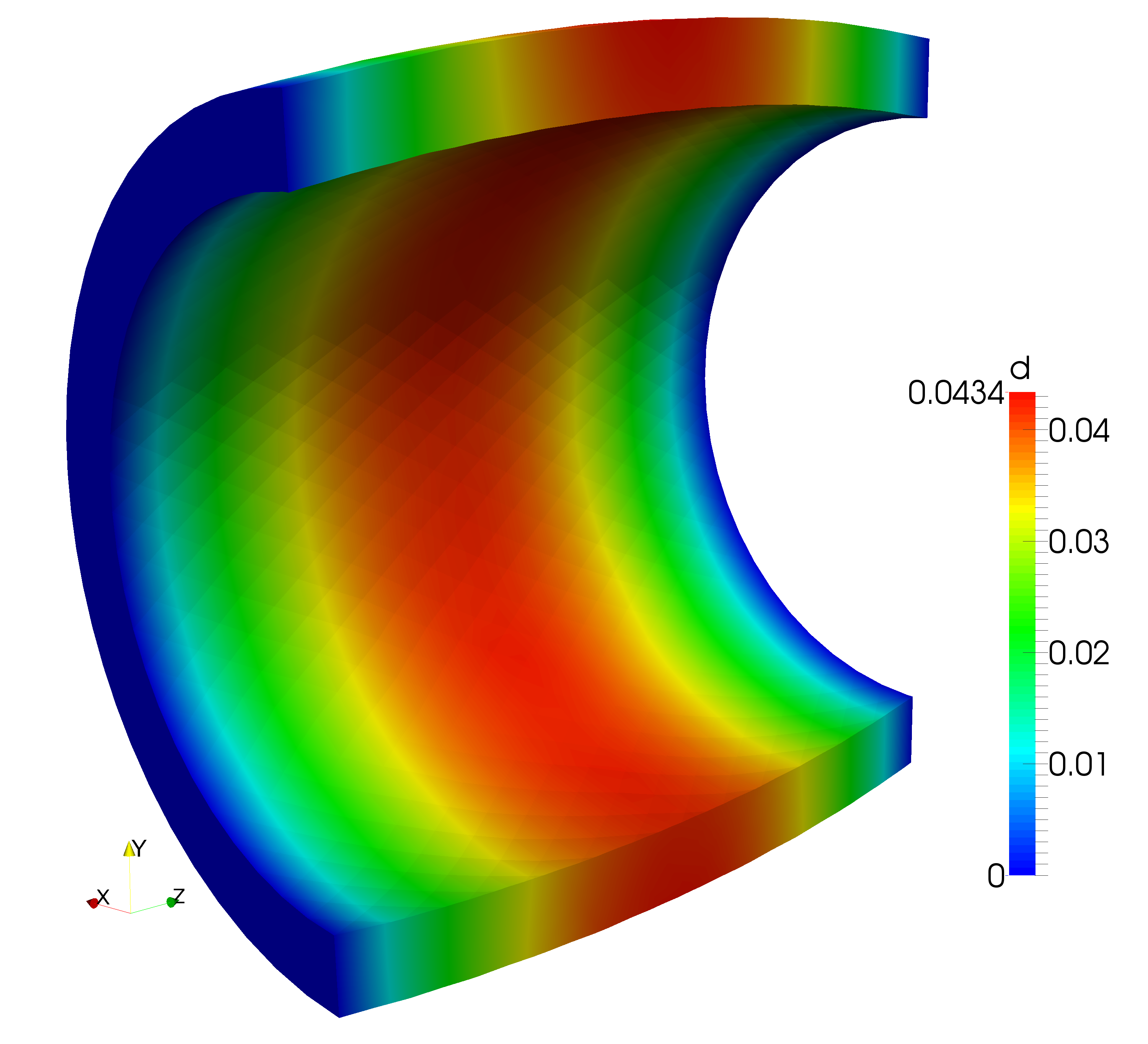
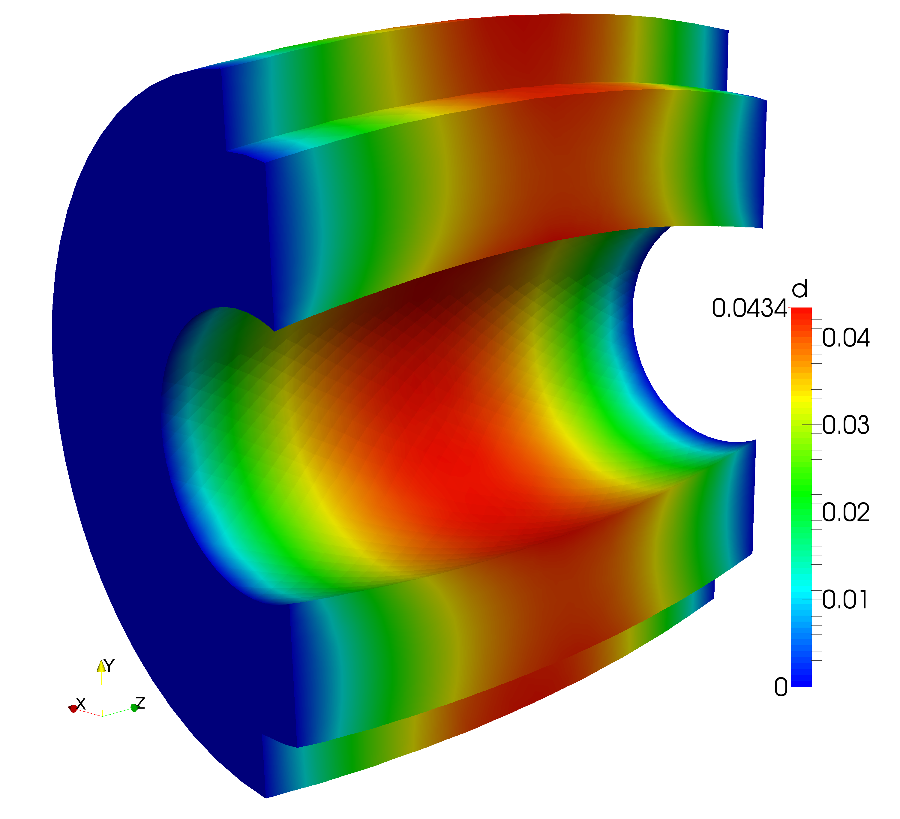
For the penalty parameters in the stabilized overlapping mesh method for the fluid problem, we pick and . Since the overall computational time is dominated by the assembly and solution of the fluid system, the displacement field is conveniently solved using a direct solver, while the linear system arising from the fluid problem is solved by applying a transpose-free quasi-minimal residual solver with an algebraic multigrid preconditioner.
Using continuous piecewise linear functions for the approximation of both the fluid velocity, fluid pressure and the structure displacement, the theoretically predicted convergence rate for a corresponding uncoupled problem is at least when measuring the velocity and displacement error in the -norm and the pressure error in the -norm. Note that it is common to observe a higher experimental order of convergence of for the pressure approximation when stabilized, equal-order interpolation elements are used to discretize the flow problem. Assuming at most quadratic convergence of the displacement solution in the -norm, the -error will be reduced by approximately after 3 uniform mesh refinements. To not pollute the overall convergence rate by the iteration error, we therefore chose for the relative -error between two consecutive displacement solutions computed in the iteration loop. With the given tolerance, the Dirichlet-Neumann iteration converged after - iteration for each refinement level. The resulting errors for the sequence of refined meshes are summarized in Table 5.1. For the fluid velocity and fluid pressure the observed convergence rates are in agreement with the theoretical error decrease expected from an uncoupled problem. For the solid displacement the observed convergence rates between - for the -error are better than the theoretically expected rate of .
| Refinement | EOC | EOC | EOC | |||
|---|---|---|---|---|---|---|
| 0 | - | - | - | |||
| 1 | 0.99 | 1.22 | 1.46 | |||
| 2 | 1.22 | 2.06 | 1.68 | |||
| 3 | 0.81 | 1.52 | 1.9 |
5.3. Flow around an elastic flap
In the second numerical example, we consider a channel flow around an elastic flap for different orientations of the flap with respect to the channel geometry. Here, the developed method and techniques can play out their full strength as the overlapping mesh approach handles large deformation within a single simulation easily. As an additional benefit, our proposed scheme allows to seamlessly reposition the flap for a series of numerical experiments and thus has great potential for future applications in design and optimization processes which involve fluid–structure interaction problems in their forward simulation, see for instance [43, 22].
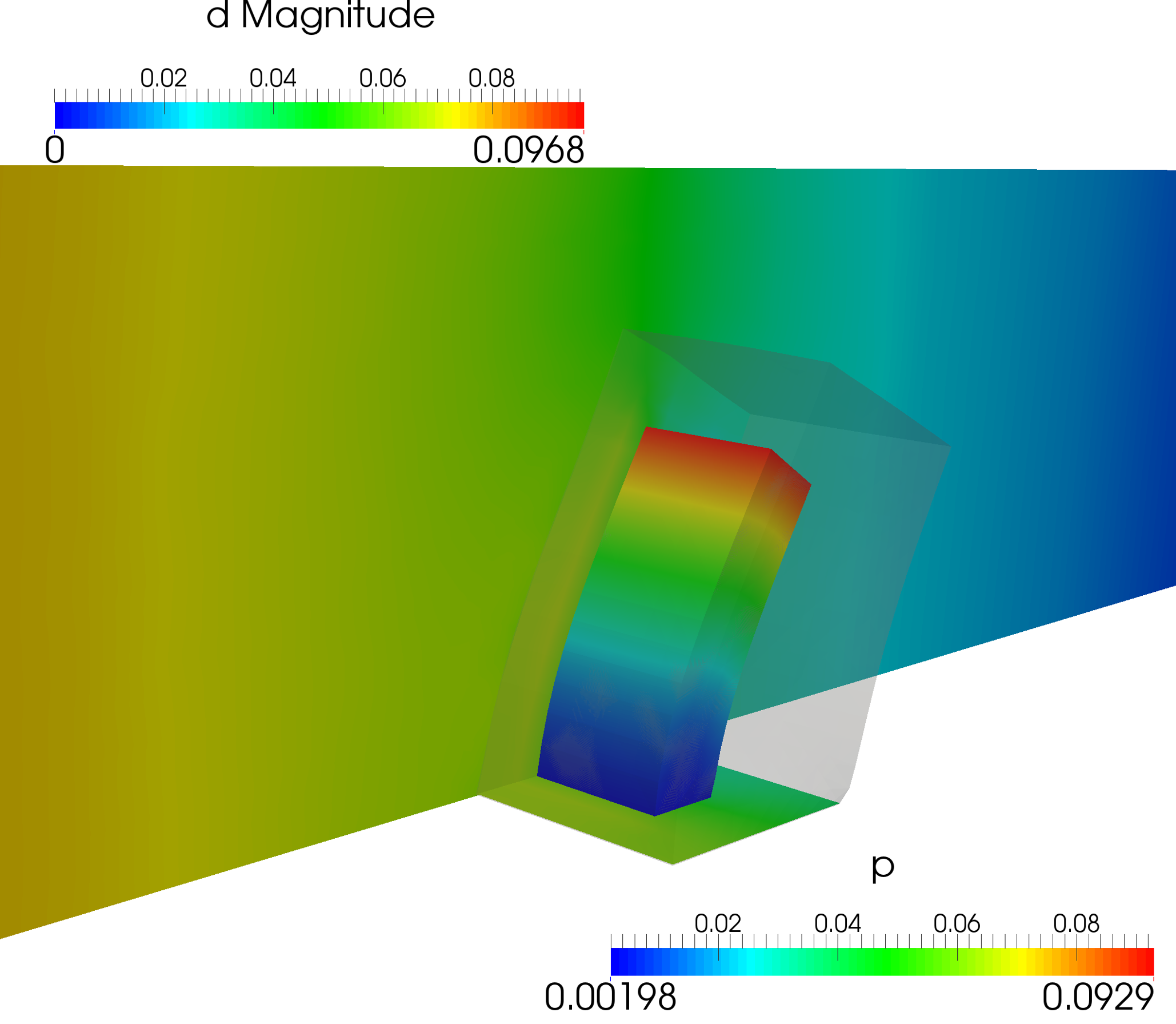
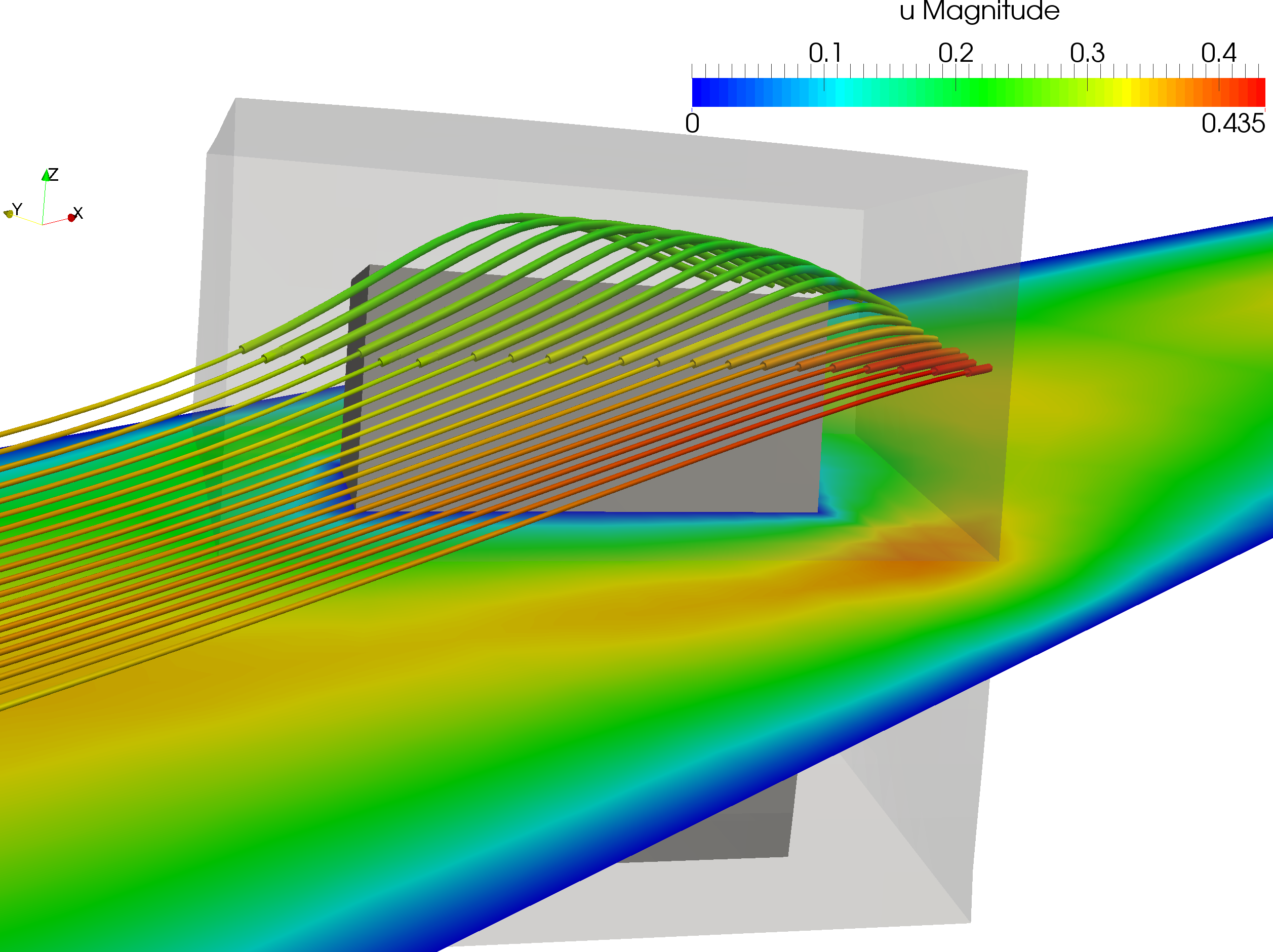
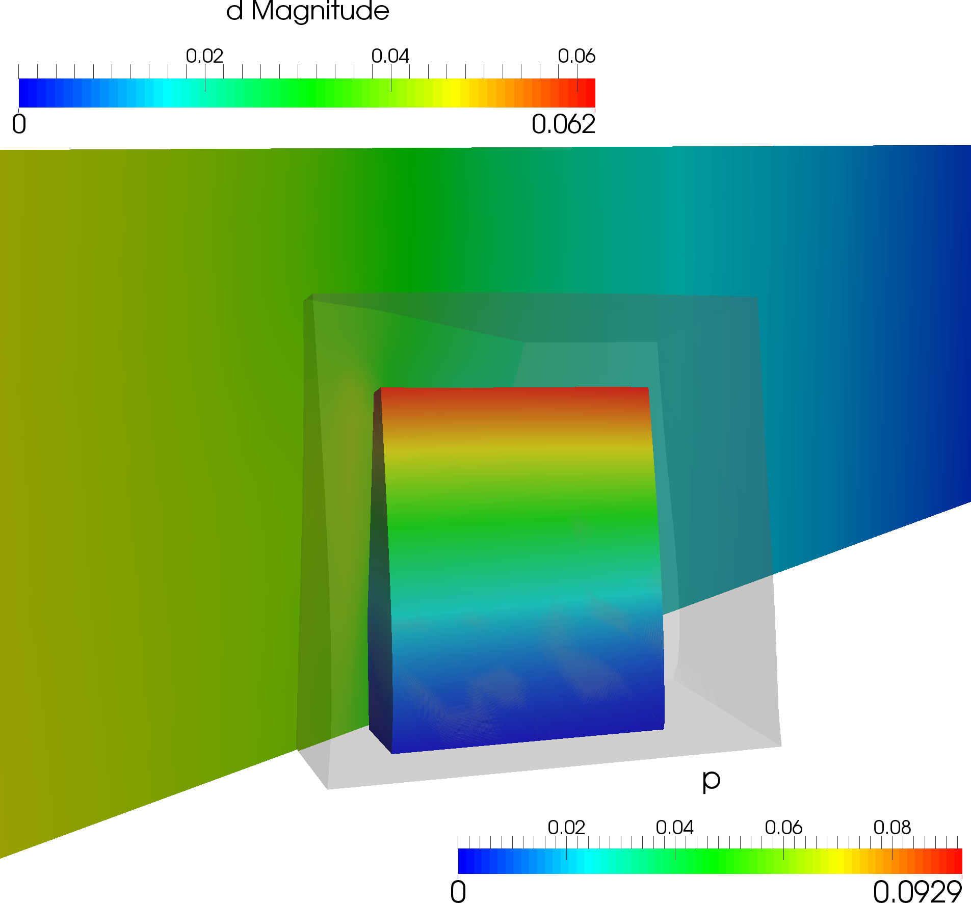
Within the channel domain with , , the bottom side of the flap of dimensions , , is centered around the point . In the first numerical experiment, the flap is clamped on the boundary , while the flap is rotated around the -axis in a second experiment. For the numerical experiment, we assume that the flow can be described by the Stokes equations with fluid viscosity , while the flap is modeled as an hyperelastic material satisfying the St. Venant–Kirchhoff constitutive equation (3.18) with the Lamé constants defined by (5.4) for and . Finally, we prescribe the inflow profile at the inlet , a “do-nothing” boundary condition given by at the outlet and a no-slip condition elsewhere on the boundary.
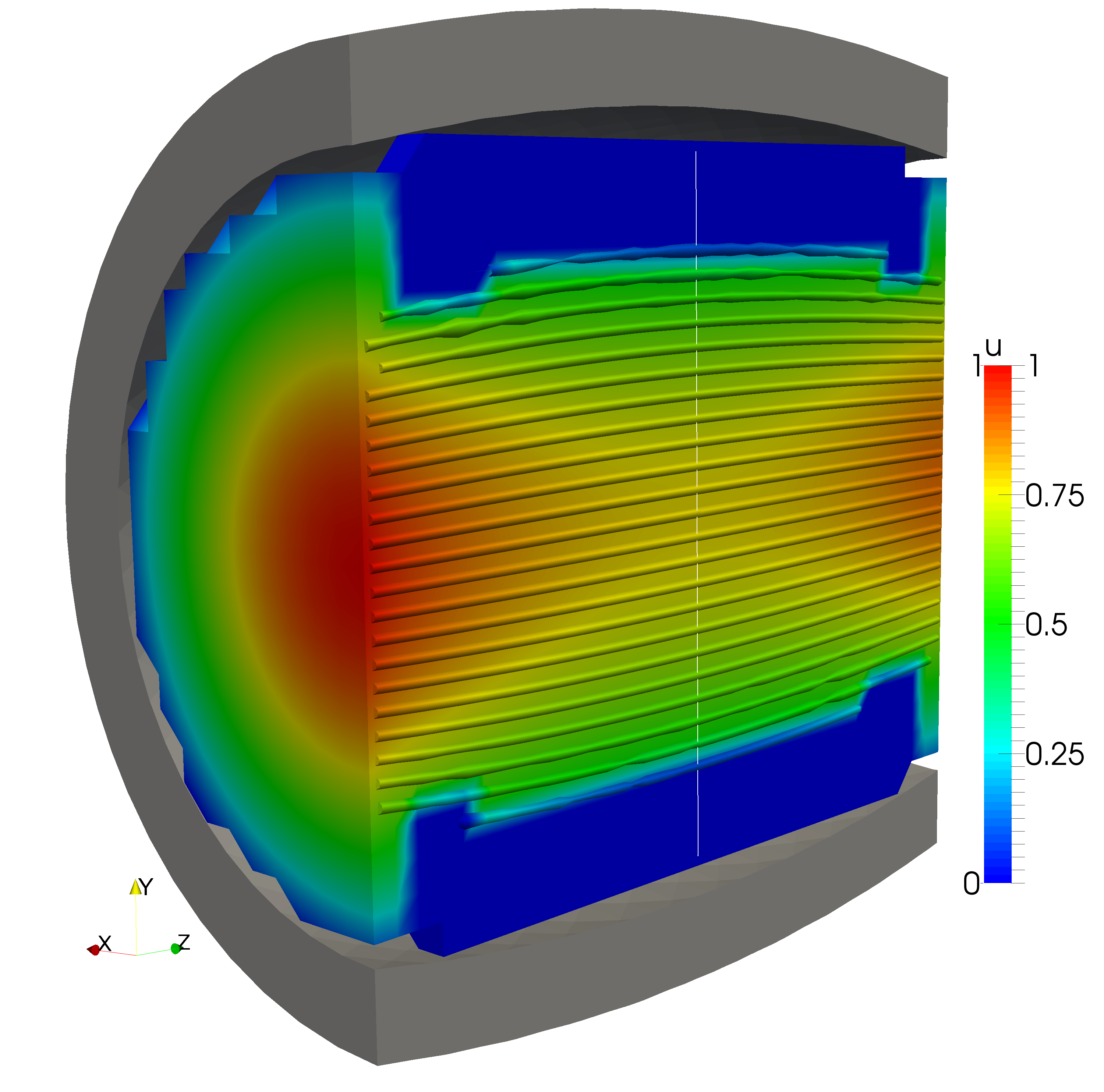
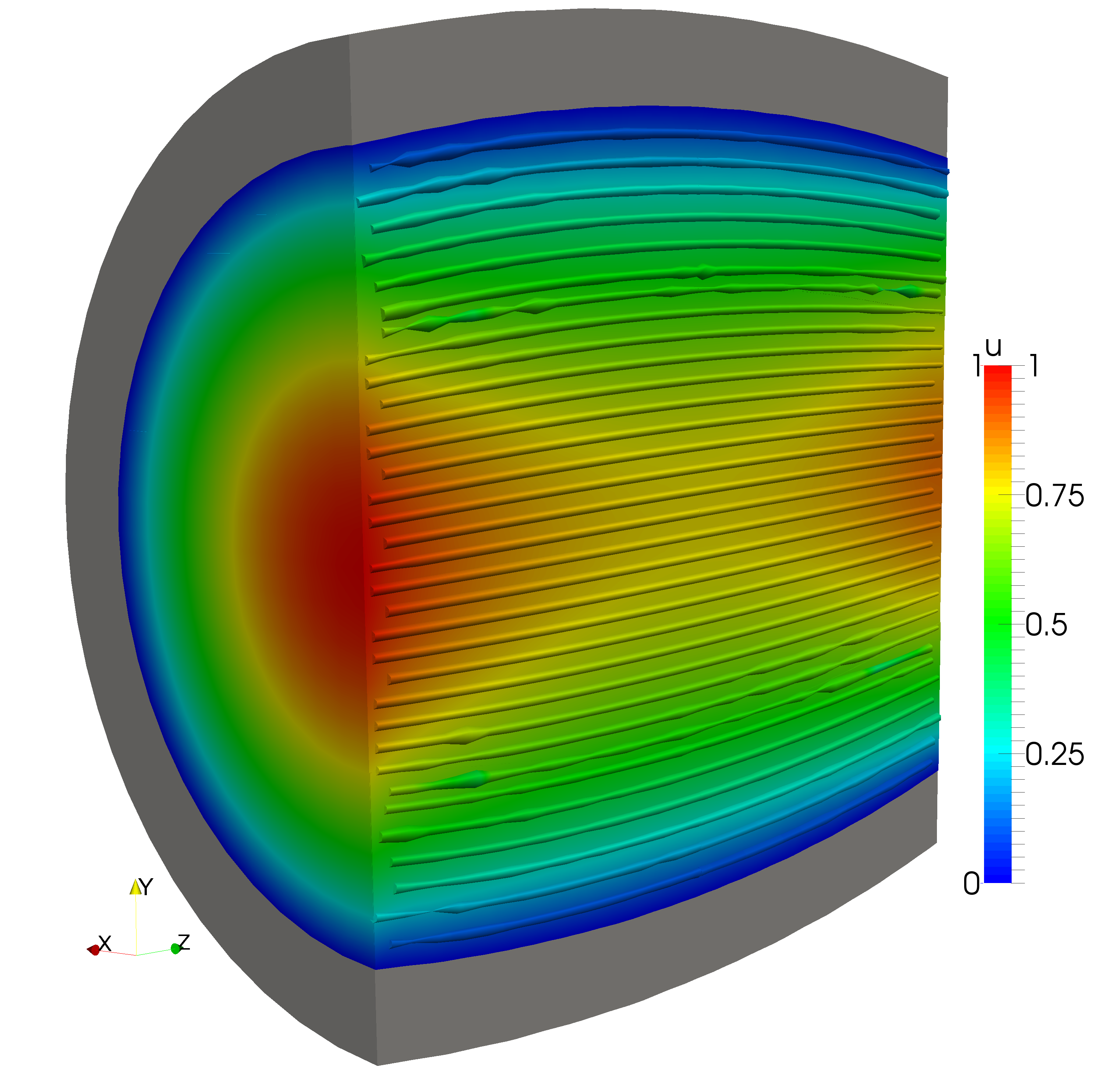
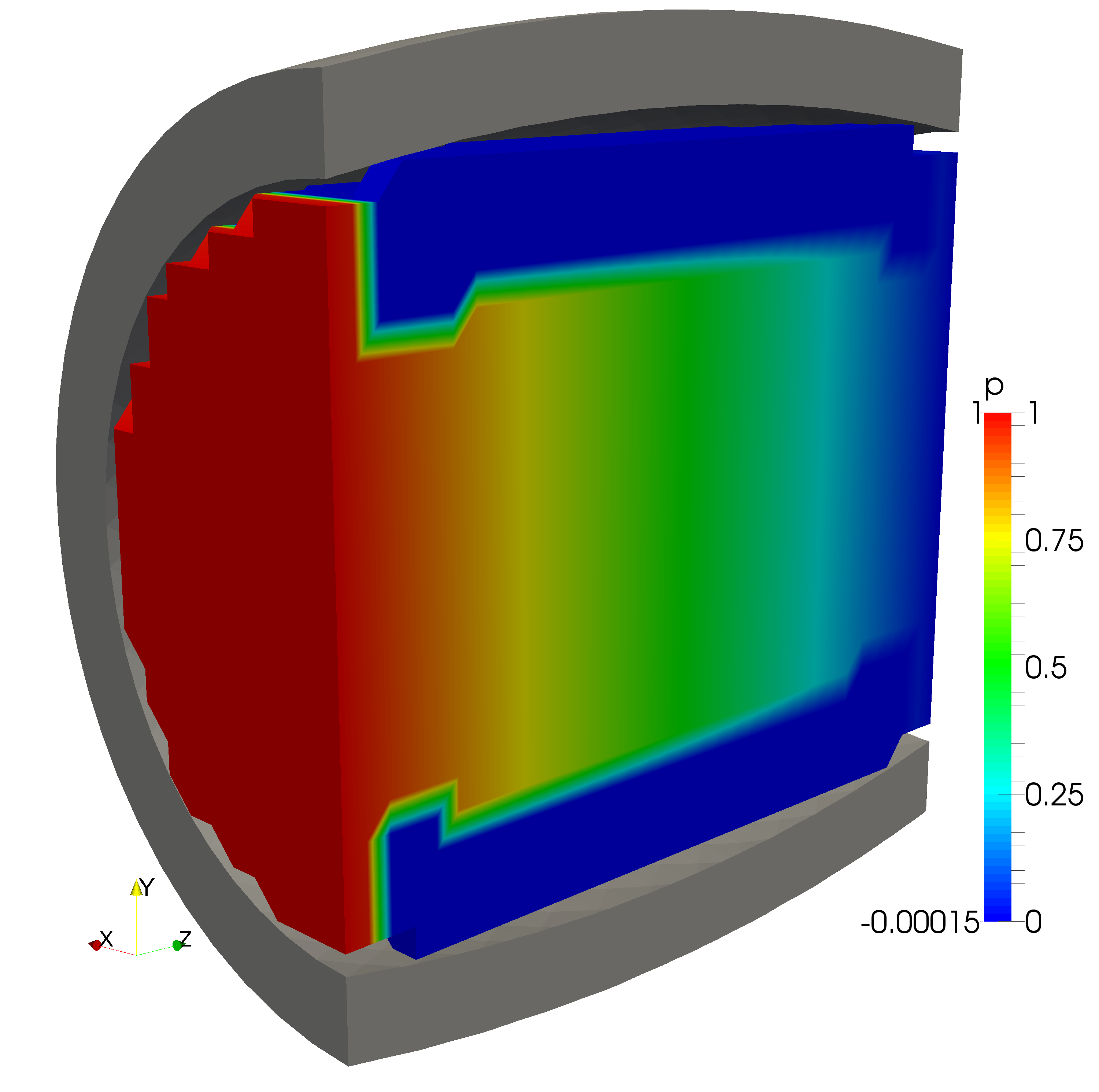
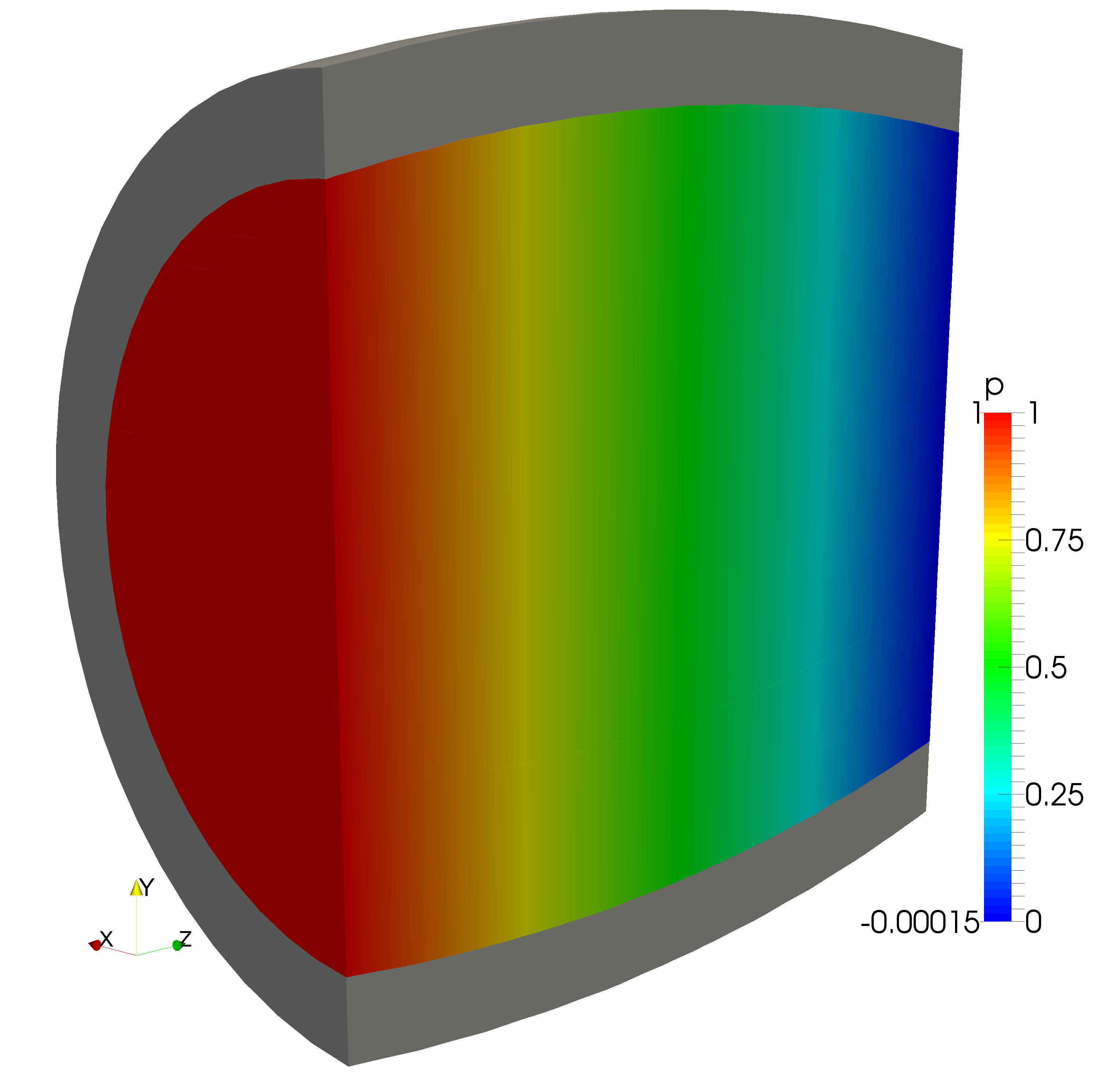
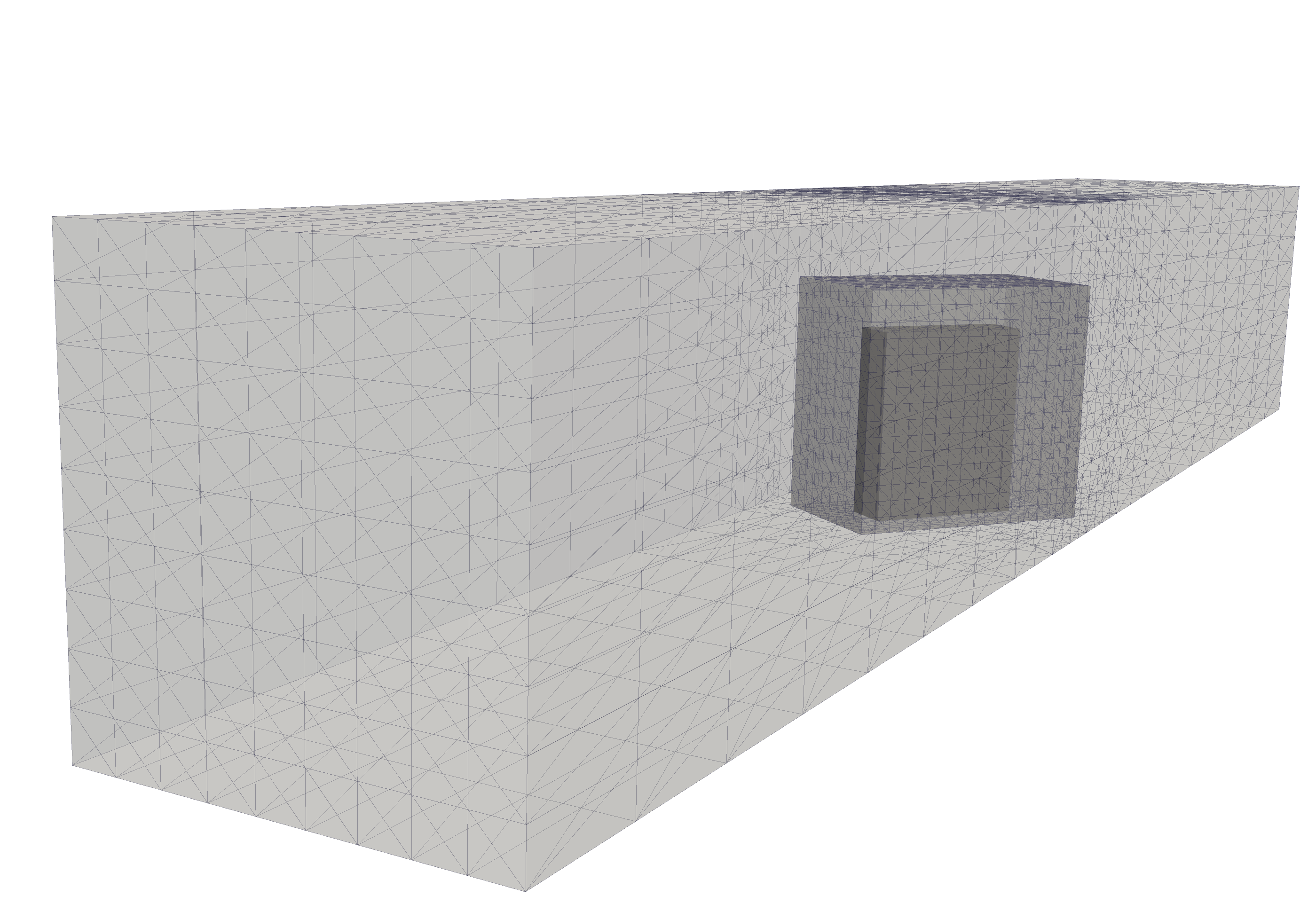
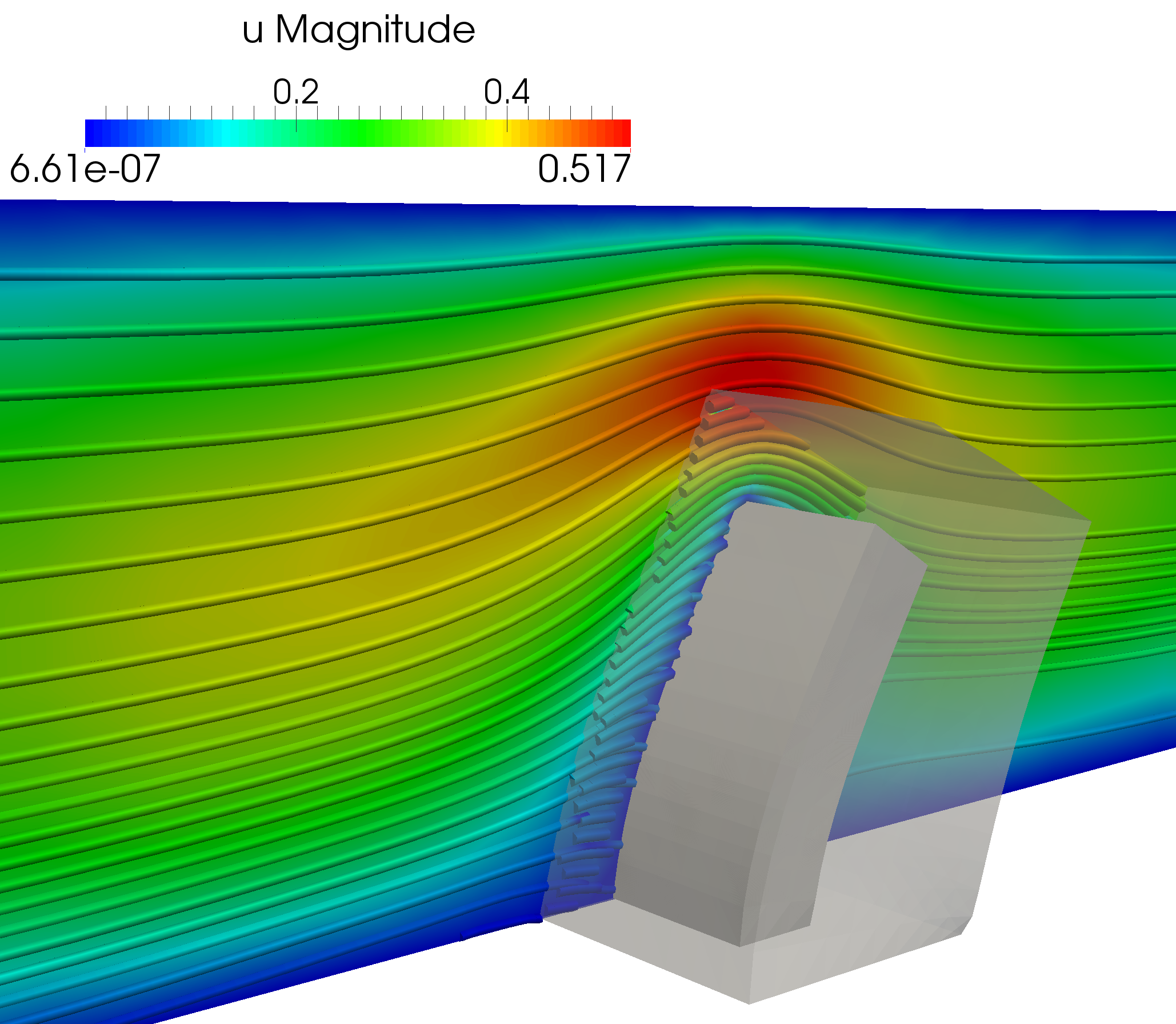
The numerical results for aligned and rotated flaps are shown in Figure 5.5. We especially note the smooth transition of the velocity and pressure solutions from fluid background to the solid-surrounding fluid mesh ; the interface is not visible. The meshes used for simulation of the rotated flap are shown in Figure 5.4.
6. Conclusions
We presented a Nitsche-based cut and composite mesh method for fluid–structure interaction problems. The method utilizes a Nitsche type coupling between two fluid meshes: one fixed background mesh and one moving overlapping fluids mesh which is fitted to the boundary of a hyperelastic object and deforms with the object. The fluid–fluid coupling is monolithic in the sense that it manufactures a coupled system involving both the underlying and overlapping degrees of freedom. In previous work, [45], we have shown that the coupling is stable and that the solution has optimal order convergence for a stationary model problem.
To solve for the steady state solution of a fluid–structure interaction problem with large elastic deformations, we consider a fixed-point iteration where we solve for the fluid, compute a boundary traction for the solid, solve for the solid, solve for the mesh motion of the overlapping fluid mesh, and finally update the geometry. This involves computing new intersections between underlying and overlapping meshes. Employing a provably stable overlapping mesh method for fluid-fluid coupling, the proposed scheme for the fluid–structure problem is guaranteed to be robust and insensitive to the overlap configuration.
We verified the expected convergence rates for a model problem with a manufactured solution and demonstrated the flexibility of our approach by computing the steady state solution for an elastic flap in a channel at two different orientations. It should be noted that the overlapping mesh method allows the flap to be repositioned in the channel without requiring the generation of a single conforming fluid mesh for each configuration. Only an element-wise, local representation of the cut cells near the interface together with some appropriate quadrature schemes are required, see for instance [44].
Future work involves extending our method to fully time-dependent flow governed by the incompressible Navier-Stokes equations. We note that the nonlinear convection term can be handled in our setting using a discontinuous Galerkin coupling with up-winding and that, from a computational point of view, taking a time step is closely related to taking one step in our fixed-point iteration algorithm. Another area of interest is the direct coupling between fluids and solids.
Acknowledgments
This work is supported by an Outstanding Young Investigator grant from the Research Council of Norway, NFR 180450. This work is also supported by a Center of Excellence grant from the Research Council of Norway to the Center for Biomedical Computing at Simula Research Laboratory. The authors would like thank the anonymous referee for the valuable comments and suggestions which helped to improve the presentation of this work.
References
- [1] Cgal, Computational Geometry Algorithms Library, software package.
- [2] gts, GNU Triangulated Surface Library, software package.
- Aftosmis et al. [1998] Michael J Aftosmis, Marsha J Berger, and John E Melton. Robust and efficient cartesian mesh generation for component-based geometry. AIAA journal, 36(6):952–960, 1998.
- Alnæs [2012] Martin S. Alnæs. UFL: a Finite Element Form Language, chapter 17. Springer, 2012.
- Alnæs et al. [2012] Martin S. Alnæs, Anders Logg, and Kent-Andre Mardal. UFC: a Finite Element Code Generation Interface, chapter 16. Springer, 2012.
- Alnæs et al. [2014] Martin S. Alnæs, Anders Logg, Kristian B. Ølgaard, Marie E. Rognes, and Garth N. Wells. Unified form language: A domain-specific language for weak formulations of partial differential equations. ACM Transactions on Mathematical Software, 40(2), 2014.
- Badia et al. [2008a] Santiago Badia, Fabio Nobile, and Christian Vergara. Fluid-structure partitioned procedures based on Robin transmission conditions. J. Comput. Phys., 227(14):7027–7051, July 2008a. ISSN 00219991.
- Badia et al. [2008b] Santiago Badia, Fabio Nobile, and Christian Vergara. Fluid–structure partitioned procedures based on robin transmission conditions. J. Comput. Phys., 227(14):7027–7051, 2008b.
- Badia et al. [2009] Santiago Badia, Fabio Nobile, and Christian Vergara. Robin-Robin preconditioned Krylov methods for fluid-structure interaction problems. Computer Methods in Applied Mechanics and Engineering, 198(33-36):2768–2784, July 2009. ISSN 00457825.
- Baiges and Codina [2009] J Baiges and R Codina. The fixed-mesh ALE approach applied to solid mechanics and fluid-structure interaction problems. Int. J. Numer. Methods Eng., 81:1529–1557, 2009.
- Banks et al. [2012] Jeffrey W Banks, William D Henshaw, and Donald W Schwendeman. Deforming composite grids for solving fluid structure problems. J. Comput. Phys., 231(9):3518–3547, 2012.
- Boffi and Gastaldi [2003] Daniele Boffi and Lucia Gastaldi. A finite element approach for the immersed boundary method. Computers & structures, 81(8):491–501, 2003.
- Burman and Hansbo [2013] E. Burman and P. Hansbo. Fictitious domain methods using cut elements: III. A stabilized nitsche method for stokes’ problem. ESAIM, Math. Model. Num. Anal., page 19, 2013.
- Burman et al. [2014] E. Burman, S. Claus, P. Hansbo, M.G. Larson, and A. Massing. Cutfem: discretizing geometry and partial differential equations. Int. J. Numer. Meth. Engng, 12 2014.
- Burman et al. [2015] E. Burman, S. Claus, and A. Massing. A Stabilized Cut Finite Element Method for the Three Field Stokes Problem. Accepted for publication in SIAM J. Sci. Comput., 2015.
- Cebral and Löhner [2005] J.R. Cebral and R. Löhner. Efficient simulation of blood flow past complex endovascular devices using an adaptive embedding technique. Med. Imaging, IEEE Trans., 24(4):468–476, 2005.
- Chesshire and Henshaw [1990] G. Chesshire and W. D. Henshaw. Composite overlapping meshes for the solution of partial differential equations. J. Comput. Phys., 90(1):1–64, 1990.
- Day and Bochev [2008] D. Day and P. Bochev. Analysis and computation of a least-squares method for consistent mesh tying. J. Comput. Appl. Math., 218(1):21–33, August 2008.
- Donea et al. [1982] J Donea, S Giuliani, and JP Halleux. An arbitrary lagrangian-eulerian finite element method for transient dynamic fluid-structure interactions. Computer methods in applied mechanics and engineering, 33(1):689–723, 1982.
- Donea et al. [2004] Jean Donea, Antonio Huerta, J-Ph Ponthot, and Antonio Rodríguez-Ferran. Arbitrary Lagrangian–Eulerian methods. Encyclopedia of computational mechanics, 2004.
- Dorok [1995] O. Dorok. Eine stabilisierte Finite-Elemente-Methode zur Lösung der Boussinesq-Approximation der Navier-Stokes-Gleichungen. PhD thesis, Otto von Guericke University Magdeburg, 1995.
- Eguzkitza et al. [2014] B Eguzkitza, G Houzeaux, H Calmet, M Vázquez, B Soni, S Aliabadi, A Bates, and D Doorly. A gluing method for non-matching meshes. Computers & Fluids, 2014.
- English et al. [2013] RE English, Linhai Qiu, Yue Yu, and Ronald Fedkiw. An adaptive discretization of incompressible flow using a multitude of moving Cartesian grids. J. Comput. Phys., 254:107–154, 2013.
- Gerstenberger and Wall [2008a] A. Gerstenberger and W. A. Wall. An extended finite element method/Lagrange multiplier based approach for fluid–structure interaction. Comput. Methods Appl. Mech. Engrg., 197(19-20):1699–1714, 2008a.
- Gerstenberger and Wall [2008b] A. Gerstenberger and W. A. Wall. Enhancement of fixed-grid methods towards complex fluid-structure interaction applications. International Journal for Numerical Methods in Fluids, 57(9):1227–1248, 2008b.
- Giles et al. [1997] M. Giles, M. Larson, M. Levenstam, and E. Süli. Adaptive error control for finite element approximations of the lift and drag coefficients in viscous flow. 1997.
- Hansbo et al. [2003] A. Hansbo, P. Hansbo, and Mats G. Larson. A Finite Element Method on Composite Grids based on Nitsche’s Method. ESAIM, Math. Model. Num. Anal., 37(3):495–514, 2003.
- Hansbo and Hermansson [2003] P. Hansbo and J. Hermansson. Nitsche’s method for coupling non-matching meshes in fluid-structure vibration problems. Comput. Mech., 32(1-2):134–139, 2003.
- Hansbo et al. [2014] Peter Hansbo, Mats G Larson, and Sara Zahedi. A cut finite element method for a stokes interface problem. Applied Numerical Mathematics, 85:90–114, 2014.
- Henshaw and Schwendeman [2006] William D Henshaw and Donald W Schwendeman. Moving overlapping grids with adaptive mesh refinement for high-speed reactive and non-reactive flow. Journal of Computational Physics, 216(2):744–779, 2006.
- Houzeaux and Codina [2003] G. Houzeaux and R. Codina. A Chimera method based on a Dirichlet/Neumann(Robin) coupling for the Navier–Stokes equations. Computer Methods in Applied Mechanics and Engineering, 192(31-32):3343–3377, August 2003. ISSN 00457825.
- John [1997] V. John. Parallele Lösung der inkompressiblen Navier-Stokes Gleichungen auf adaptiv verfeinerten Gittern. PhD thesis, Otto von Guericke University Magdeburg, 1997.
- Kirby and Logg [2006] Robert C Kirby and Anders Logg. A Compiler for Variational Forms. ACM Trans. Math. Softw., 32(3):417–444, 2006.
- Küttler and Wall [2008] Ulrich Küttler and Wolfgang A. Wall. Fixed-point fluid–structure interaction solvers with dynamic relaxation. Computational Mechanics, 43(1):61–72, February 2008. ISSN 0178-7675.
- Küttler and Wall [2009] Ulrich Küttler and Wolfgang A. Wall. Vector Extrapolation for Strong Coupling Fluid-Structure Interaction Solvers. Journal of Applied Mechanics, 76(2):021205, 2009. ISSN 00218936.
- Le Tallec and Mouro [2001] P. Le Tallec and J. Mouro. Fluid structure interaction with large structural displacements. Computer Methods in Applied Mechanics and Engineering, 190(24-25):3039–3067, March 2001. ISSN 00457825.
- Logg [2007] Anders Logg. Automating the finite element method. Arch. Comput. Methods Eng., 14(2):93–138, 2007.
- Logg and Wells [2010] Anders Logg and Garth N. Wells. DOLFIN: Automated finite element computing. ACM Trans. Math. Softw., 37(2), 2010.
- Logg et al. [2012a] Anders Logg, Kent-Andre Mardal, Garth N. Wells, et al. Automated Solution of Differential Equations by the Finite Element Method. Springer, 2012a.
- Logg et al. [2012b] Anders Logg, Kristian B. Ølgaard, Marie E. Rognes, and Garth N. Wells. FFC: the FEniCS Form Compiler, chapter 11. Springer, 2012b.
- Löhner et al. [2007] R. Löhner, J.R. Cebral, F.F. Camelli, J.D. Baum, E.L. Mestreau, and O.A. Soto. Adaptive embedded/immersed unstructured grid techniques. Archives of Computational Methods in Engineering, 14(3):279–301, 2007.
- Löhner et al. [2008] Rainald Löhner, Juan R. Cebral, Fernando E. Camelli, S. Appanaboyina, Joseph D. Baum, Eric L. Mestreau, and Orlando A. Soto. Adaptive embedded and immersed unstructured grid techniques. Computer Methods in Applied Mechanics and Engineering, 197(25–28):2173 – 2197, 2008. Immersed Boundary Method and Its Extensions.
- Lund et al. [2003] Erik Lund, Henrik Møller, and Leif Anders Jakobsen. Shape design optimization of stationary fluid-structure interaction problems with large displacements and turbulence. Structural and Multidisciplinary Optimization, 25(5-6):383–392, 2003.
- Massing et al. [2013] A. Massing, M. G. Larson, and A. Logg. Efficient implementation of finite element methods on non-matching and overlapping meshes in 3D. SIAM J. Sci. Comput., 35(1):C23–C47, 2013.
- Massing et al. [2014a] A. Massing, M.G. Larson, A. Logg, and M.E. Rognes. A stabilized Nitsche overlapping mesh method for the Stokes problem. Num. Math., 128(1):73–101, September 2014a.
- Massing et al. [2014b] A. Massing, M.G. Larson, A. Logg, and M.E. Rognes. A stabilized Nitsche fictitious domain method for the stokes problem. J. Sci. Comput., 61(3):604–628, 2014b.
- Murman et al. [2003] Scott M Murman, Michael J Aftosmis, and Marsha J Berger. Implicit approaches for moving boundaries in a 3-d cartesian method. AIAA paper, 1119:2003, 2003.
- Nobile [2001] F. Nobile. Numerical Approximation of Fluid-Structure Interaction Problems with Applications to Haemodynamics. PhD thesis, École Polytechnique Fédérale de Lausanne, 2001.
- Peskin [2003] C. S. Peskin. The immersed boundary method. Acta Numerica, 11:479–517, 2003.
- Peskin [1977] C.S. Peskin. Numerical analysis of blood flow in the heart. Journal of Computational Physics, 25(3):220–252, 1977.
- Puso et al. [2014] MA Puso, E Kokko, R Settgast, J Sanders, B Simpkins, and B Liu. An embedded mesh method using piecewise constant multipliers with stabilization: mathematical and numerical aspects. International Journal for Numerical Methods in Engineering, 2014.
- Shahmiri et al. [2011] S. Shahmiri, A. Gerstenberger, and W.A. Wall. An XFEM-based embedding mesh technique for incompressible viscous flows. International Journal for Numerical Methods in Fluids, 65(November 2010):166–190, 2011.
- Starius [1977] Göran Starius. Composite mesh difference methods for elliptic boundary value problems. Numerische Mathematik, 28(2):243–258, 1977.
- Starius [1980] Göran Starius. On composite mesh difference methods for hyperbolic differential equations. Numerische Mathematik, 35(3):241–255, 1980.
- Steger et al. [1983] J. L. Steger, F.C. Dougherty, and J.A. Benek. A Chimera grid scheme. In K.N. Ghia and U. Ghia, editors, Advances in Grid Generation, volume 5. ASME, 1983.
- Volkov [1968] Evgenii Alekseevich Volkov. The method of composite meshes for finite and infinite regions with piecewise smooth boundary. Trudy Matematicheskogo Instituta im. VA Steklova, 96:117–148, 1968.
- Wall et al. [2006] Wolfgang A. Wall, Axel Gerstenberger, Peter Gamnitzer, Christiane Förster, and Ekkehard Ramm. Large deformation fluid-structure interaction–advances in ale methods and new fixed grid approaches. In Fluid-structure interaction, pages 195–232. Springer, 2006.
- Wang et al. [2000] ZJ Wang, V Parthasarathy, and N Hariharan. A fully automated Chimera methodology for multiple moving body problems. Internation Journal for Numerical Methods in Fluids, 33(7):919–938, 2000.
- Yu [2005] Z. Yu. A DLM/FD method for fluid/flexible-body interactions. Journal of Computational Physics, 207(1):1–27, 2005.
- Zhang et al. [2004] L. Zhang, A. Gerstenberger, X. Wang, and W. K. Liu. Immersed finite element method. Comput. Methods Appl. Mech. Engrg., 193(21-22):2051–2067, 2004.
- Zhang and Gay [2007] LT Zhang and M Gay. Immersed finite element method for fluid-structure interactions. Journal of Fluids and Structures, 23(6):839–857, 2007.