smith_joe
EDS’13
ATLAS results on soft diffraction
Abstract
The measurements of the total inelastic cross section and the differential inelastic cross section as a function of rapidity gap are presented. The data used for these studies were collected in collisions at a center-of-mass energy of 7 TeV with the ATLAS detector at the LHC in 2010.
1 Introduction
This report presents the measurements of the total and differential inelastic cross section in collisions at a center-of-mass energy () of 7 TeV with the ATLAS detector [1] at the LHC. The total cross section has two components: the elastic and the inelastic one. This latter, in turn, is composed of 4 terms: non-diffractive (ND), single diffractive (SD), double diffractive (DD) and central diffractive (CD).
Single diffraction is a process in which one of the two protons dissociates in a final state X and the other stays intact; in double diffraction processes both protons dissociate into two final states X and Y. In single and double diffractive inelastic scattering a colourless Pomeron exchange leads to a rapidity gap, a region in rapidity devoid of particles. Finally in central diffraction processes none of the protons dissociate but a final state centrally produced arises.
Pythia6 [2], Pythia8 [3] and PHOJET [4] generators are used to predict the properties of the inelastic collisions.
Experimentally the diffractive processes are described using the kinematic variable , where is the dissociative mass of the final state X or Y and s already introduced.
2 Total inelastic cross section
The measurement of the total inelastic cross section was performed using data collected in one run in March 2010 at TeV corresponding to an integrated luminosity of 20 b-1, with a mean number of collisions per bunch crossing of about 0.01.
For triggering the Minimum Bias Trigger Scintilator (MBTS) was used. The MBTS system is composed by a set of scintillators located in front of the end-cap calorimeters of the ATLAS detector on both sides of the interaction point and covers the pseudorapidity range . The MBTS trigger is used to define two samples: single-sided events, with signal present exclusively in one side, and inclusive events, with signal in one or both sides of the detector.
The total inelastic cross section was obtained using the formula
| (1) |
where N and NBG are the number of selected and background events. The background is mainly due to beam-related interactions and was determined using the number of
events selected in correspondence with non-colliding bunches. is the integrated luminosity, the trigger efficiency (99.98 ), the selection efficiency (98.77 ) and (0.96 ) the fraction of events with , evaluated using the default Donnachie and Landshoff (DL) model [5] as implemented in Pythia 8. The MBTS acceptance was found using MC and it is used to define the fiducial region of the measurement, corresponding approximately to , that is to MX,Y greater than 15.7 GeV.
The fractional contribution of diffractive events, , is constrained by
RSS, the ratio of single-sided to inclusive events.
RSS was measured to be which, using the default
DL model, corresponds to .
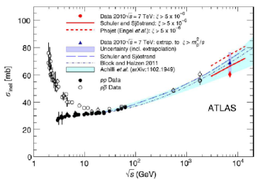
In Fig. 1 the total inelastic cross section is presented as a function of . The ATLAS measurement obtained through the equation above is represented by the red circle and is equal to mb. The phenomenological models underestimate the observed result. The extrapolated cross section (represented by the blue triangle), obtained extending the MX,Y range to the proton mass, was evaluated to be mb, consistent with the phenomenological predictions. Black and white dots refers to previous and data respectively [6].
3 Inelastic cross section as a function of rapidity gap
The differential inelastic cross section measurement was performed using data corresponding to an integrated luminosity of 7 b-1 collected with a negligible rate of multiple proton-proton interactions. The MBTS trigger was used for the online event selection.
The forward rapidity gap () is defined as the larger of the two empty pseudorapidity regions
extending between the edges of the detector acceptance
and the closest track or calorimeter cluster. On the particle level, it is defined without stable charged and neutral particles with MeV.
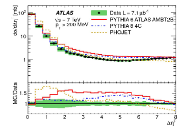
A the differential inelastic cross section as a function of rapidity gap is shown in Fig 2.
The plot shows an exponential decrease at low due to the non-diffractive events
while, for , a flat behavior is observed as predicted by the theory ( proportional to -log ).
All the MC models considered for the comparison lie above data, Pythia8 is closer than other models to the data at low ,
while PHOJET is better at intermediate values of .
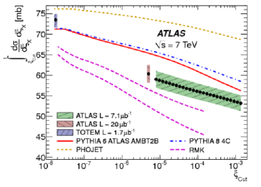
The differential inelastic cross section was also measured as a function of (requiring ). In Fig 2b, different measurements of the integrated cross section as a function of from TOTEM and ATLAS are shown together with MC predictions. The most recent results from ATLAS was obtained for different values of integration limit and are in agreement with the previous ATLAS result [7].
4 Conclusions
ATLAS measurements of the total and differential inelastic cross section at TeV have been presented. The total inelastic cross section for , within the detector acceptance, was measured to be mb while the extrapolation to the full phase space gives a value of mb. The differential inelastic cross section as a function of the rapidity gap was also measured. All the considered models overestimate the data and none of them gives a detailed description of the shape of the distribution.
References
- [1] ATLAS Collaboration, 2008 JINST 3 S08003.
- [2] T. Sjöstrand, S. Mrenna and P. Skands, JHEP 05, 026 (2006).
- [3] T. Sjöstrand, S. Mrenna and P. Skands, Comput Phys. Commun. 178 (2008) 852-867.
- [4] R. Engel, PHOJET manual (program version 1.05c, June 96), http://www-ik1.fzk.de/engel/phojet.html.
- [5] A. Donnachie, P. Landshoff, Phys. Lett. B 296, 227-232 (1992).
- [6] ATLAS Collaboration, Nat. Commun. 2 (2011) 463.
- [7] ATLAS Collaboration, Eur. Phys. J. C72 (2012) 1926.