Large enhancement of Förster resonance energy transfer on graphene platforms
Abstract
In the view of the applications of Förster resonant energy transfer (FRET) in biological systems which especially require FRET in the inrared region we investigate the great advantage of graphene plasmonics in such studies. Focusing on the fundamental aspects of FRET between a donor-acceptor pair on a graphene platform showing that FRET mediated by the plasmons in graphene is broadband and enhanced by six orders of magnitude. We briefly discuss the impact of phonon-polaritonic substrates.
March 16, 2024
I Introduction
Metal plasmonics has been investigated very intensively in the last decades. It is nowadays well known that in the visible metal structures like metal films or nanoparticles, for instance, are the plasmonic structures of choice exhibiting strong field confinement and large field enhancement close to the metallic structure. In contrast, research on graphene plasmonics which is in some sense complementary to metal plasmonics Interview has just begun. The plasmons in graphene show strong field confinement in the infrared, whereas in the visible graphene plasmonics is challenging JablanEtAl2009 ; KoppensEtAl2011 ; BrarEtAl2013 . One of the main advantages of using graphene in plasmonics or graphene-based hybrid-plasmonic devices is its tunability by doping or gating GrigorenkoEtAl2012 . Especially for applications of the Förster resonance energy transfer (FRET) such as in vivo infrared flourescence imaging applications as for example lymph-node mapping and cancer imaging HeEtAl2012 ; XiongEtAl2012 graphene plasmonics is highly suitable and can unfold its full strength.
The Förster resonant-energy transfer (FRET) itself is widely used in biochemistry to study protein and RNA folding Weiss2000 , DNA nanomechanical devices MuellerEtAl2006 and even to transport energy along a DNA backbone VyawahareEtAl2004 to mention a few applications. Theoretically it was already shown in the 80’s that in the vicinity of nanoparticles FRET between a donor and an acceptor molecule can be enhanced by two to five orders of magnitude in the idealized case when both the donor and acceptor are in resonance with the localized plasmon resonance GerstenNitzan1984 ; HuaEtAl1985 . Recent theoretical works have also studied the impact of nonlocal effects and the possibility of magneto-optical control of FRET close to metallic nanoparticles XieEtAl2009 ; VincentCarminati2011 . Although the plasmonic enhancement (PE) effect using nanoparticles could be measured lately MalickaEtAl2003 ; ReilEtAl2008 , only moderate enhancement factors of 3.5 and 8.6 were found ReilEtAl2008 . More recent experiments report FRET enhancements by a factor of 173 VigerEtAl2011 . The PE could also be demonstrated experimentally for FRET between a donor and acceptor separated by a metal film AndrewBarnes2004 .
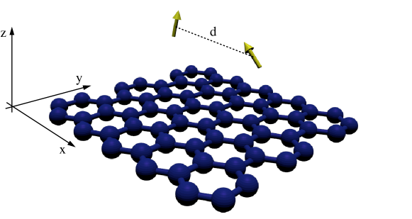
In this Letter, we demonstrate how graphene plasmonics can enhance FRET in the infrared. We want to emphasize that most recent studies are considering spontaneous emission close to graphene KoppensEtAl2011 ; VelizhaninEfimov2011 ; TislerEtAl2013 ; MessinaEtAl2013 which is a first-order process, whereas FRET is a second-order process AgarwalBook . We study in detail the FRET between a donor-acceptor pair in close vicinity to a graphene sheet as depicted in Fig. 1. We show that FRET mediated by the plasmons in the graphene sheet is broadband and can be enhanced by six orders of magnitude. The broadband property of the PE is very advantageous since one can expect large PE also in cases where the emission and absorption spectra of the donor and acceptor do not fully overlap. Further we show that the presence of graphene allows for energy transfer between perpendicularly oriented dipole moments which do not couple in free space. Finally, we discuss how the interaction of the graphene plasmons with the surface phonon polaritons of a SiC substrate affects the energy transfer. Since graphene is highly tunable this PE effect can be easily controlled even dynamically.
II Resonant dipole-dipole interaction
Using second-order perturbation theory the energy transfer rate for dipole-dipole interaction between a donor and an acceptor in the presence of arbitrarily shaped, dispersing and absorbing bodies can be written as DungEtAl2002
| (1) |
where and are the free space absorption and emission spectra of the acceptor and the donor. The energy transfer function between the donor and acceptor is DungEtAl2002
| (2) |
introducing the dipole-transition matrix elements and of the donor and acceptor. The unit vectors and determine the orientation of the dipole moments. is the permittivity of vacuum. Through the Green’s function the environment of the donor at and the acceptor at is fully taken into account. The energy transfer function can also be expressed in terms of the free space spontaneaous emission rates NovotnyHecht
| (3) |
We obtain
| (4) |
By normalizing the emission and absorption spectra by the free space emission rates and we can rewrite the expression for the energy transfer as
| (5) |
introducing the dimensionless energy transfer function
| (6) |
The enhancement factor for the energy transfer close to a plasmonic structure like graphene in comparison to vacuum is defined as
| (7) |
where the Green’s function is a sum of the vacuum Green’s function and the scattered Green’s function . The explicit expressions of the Green’s functions for free space and planar structures can be found in Refs. NovotnyHecht ; Sipe (see also Supporting Information).
III Optical properties of graphene
Before we can determine the energy transfer rate between the donor and acceptor close to a sheet of graphene it is necessary to determine its optical properties which enter in the scattered Green’s function. The optical properties of graphene are fully described by its in-plane conductivity
| (8) |
consisting of the Drude-like intraband contribution and the interband contribution which are given by FalkovskyVarlamov2007
| (9) | ||||
| (10) |
where
| (11) |
Here is the temperature of the graphene sheet, is its Fermi-level which can be tuned by gating and doping for instance. is a phenomenological damping constant, is Boltzmann’s constant, is Planck’s constant and is the electron charge. The in-plane conductivity enters in the Fresnel reflection coefficients. For a graphene sheet on a dielectric substrate with permittivity the reflection coefficients for s- and p-polarized light are given by StauberEtAl2008 ; KoppensEtAl2011 (see also Supporting Information)
| (12) | ||||
| (13) |
where is the in-plane wave vector and and are the out-of-plane wave vectors inside the substrate and in vacuum. The substrate can have quite a large impact on the properties of the plasmons in graphene, in particular, when it supports surface phonon polaritons like SiO2 and SiC KochEtAl2012 ; YanEtAl2013 ; MessinaEtAl2013 . For convenience we will neglect the influence of the substrate in the following and focus mainly on suspended graphene.
IV Plasmons in graphene
The plasmons in graphene propagating along the sheet are determined by the poles of the reflection coefficient for p polarization. When assuming that we have suspended graphene () then the dispersion relation of the plasmon simply reads
| (14) |
From this dispersion relation one can easily determine the wavelength and the propagation length of the plasmon. For a relatively high Fermi level which can be realized nowadays GrigorenkoEtAl2012 Table 1 summarizes some of the plasmon properties as the in-plane confinement and the propagation length for frequencies ranging from . The in-plane confinement is in this case strong and can attain values of to . The out-of-plane confinement is even stronger: since the out-of-plane wave vector is approximately the out-of-plane confinement is given by . This means that the out-of-plane confinement is between and . The propagation length of the plasmons in graphene is found to be between and depending on the frequency so that is between and . Note that the propagation length approximately scales linearly with the relaxation time so that can even reach values on the order of 100 for as shown in Ref. KoppensEtAl2011 . Further note that the plasmon properties can be easily tuned by changing the Fermi level by gating or tuning.
| frequency (eV) | () | (nm) | ||
|---|---|---|---|---|
| 0.2 | 6.23 | 0.072 | 2142 | 4.8 |
| 0.3 | 4.15 | 0.047 | 1397 | 7.08 |
| 0.5 | 2.49 | 0.027 | 773 | 11.3 |
| 0.7 | 1.78 | 0.018 | 486 | 14.9 |
| 0.9 | 1.38 | 0.013 | 311 | 17.4 |
V Large FRET mediated by graphene plasmons
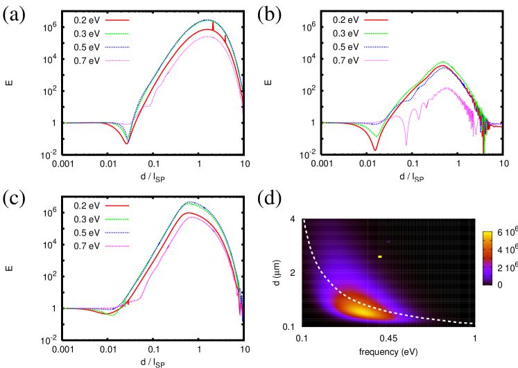
In order to demonstrate the PE we consider a donor and an acceptor on a plane parallel to the graphene sheet. The distance of this plane to the sheet of graphene which is assumed to be in the x-y plane is choosen to be . In Fig. 2(a)-(c) the enhancement factor defined in Eq. 7 is plotted as a function of distance between the donor and the acceptor for parallely aligned dipole moments along the , and axis. It can be seen that FRET mediated by the plasmons in graphene can be six orders of magnitude larger than in free space. That means that also the recently studied nonparaxial spin-Hall effect of light AgarwalBiehs2013 will be extraordinary large in the vicinity of graphene. Further the maximum enhancement is obtained for distances on the order of the propagation length of the graphene plasmons. In Fig. 2(d) we show a plot of the enhancement factor as a function of distance and frequency for the case where the dipole moments of the donor and acceptor are oriented along the z axis. It becomes apparent that the PE is broadband in frequency for distances between and . Hence, one can expect that the predicted large enhancement of FRET can be achieved in the realistic case where the emission and absorption spectra of the donor and acceptor are nonresonant in contrast to the case of metallic nanoparticles where the resonance of the localized plasmon is narrow band.
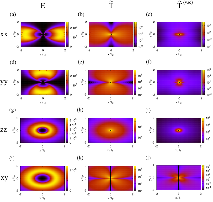
In Fig. 3(a),(d),(g),(j) we show plots of where the acceptor is placed at and the x-y position of the donor position is varied. Once more it becomes obvious that the largest enhancement factors can be obtained for distances around the propagation length of the graphene plasmons . In addition, we have plotted the energy transfer function above graphene and in free space . Note that the enhancement factor is invariant under rotation around the axis for and although and are not.
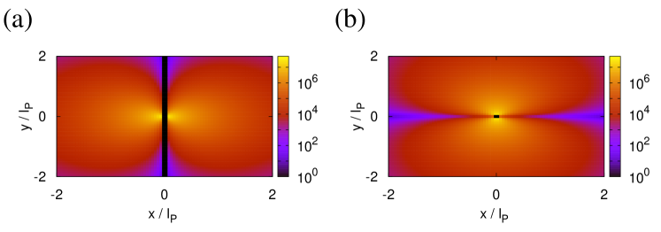
It is interesting to note that due to the presence of the graphene sheet there is also FRET between the donor and acceptor for (, ) and (,). The free space FRET vanishes in this case so that is not a well defined quantity for such orientations of dipole moments. But the energy transfer function shown in Fig. 4 indicate that the PE of FRET is in the same order of magnitude as for the cases considered in Fig. 3.
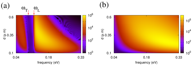
Finally, we briefly discuss the impact of the substrate. In Fig. 5(a) we show a plot of the enhancement factor of FRET above a graphene sheet deposited on SiC as a function of frequency and distance. We choose and . For comparison we also plot the enhancement factor for suspended graphene in Fig. 5(b) using the same parameters (for similar plots using see Supporting Information). In contrast to the results found in Fig. 5(b) we can see a gap of negligible small FRET in the reststrahlen region of SiC (i.e. frequencies between the transversal and longitudinal phonon frequencies and ) KochEtAl2012 ; MessinaEtAl2013 . In addition, due to the interaction of the graphene plasmon with the surface-phonon polaritons in SiC the PE is redshifted and concentrated at frequencies slighty larger than . It can also be seen that the enhancement factor on graphene/SiC is slightly smaller and the effect is more narrowband compared to the case of suspended graphene. Hence, by choosing an active or inactive substrate the observed FRET enhancement can be further controlled.
VI Conclusion
In summary we have shown that in close vicinity to a sheet of graphene FRET can be enhanced by six orders of magnitude. The maximum enhancement is obtained for donor-acceptor distances on the order of the propagation length of the plasmons in graphene. Further, we have shown that the enhancement effect is broadband and depends not only on the relative position of the donor and acceptor but also on the orientation of their dipole moments. In particular, the presence of graphene allows for coupling of perpendicularly oriented dipole moments which do not couple in free space. The role of the substrate is briefly discussed using SiC. Hence, the observed plasmonic enhancement can be tuned by doping or gating of graphene and by choosing an appropriate substrate.
References
- (1) Nat. Photon. 2013, 7, 420.
- (2) M. Jablan, H. Buljan, and M. Soljacic, Phys. Rev. B 2009, 80, 245435.
- (3) F. H. L. Koppens, D. E. Chang, and F. J. Garcia de Abajo, Nano Lett. 2011, 11, 3370-3377.
- (4) V. W. Brar, M. S. Jang, M. Sherrott, J. J. Lopez, and H. A. Atwater, Nano Lett. 2013, 13, 2541-2547.
- (5) A. N. Grigorenko, M. Polini, and K. S. Novoselov, Nat. Phot. 2012, 6, 749-758.
- (6) X. He, Y. Wang, K. Wang, M. Chen, and S. Chen, Anal. Chem. 2012, 84, 9056-9064.
- (7) L. Xiong, A. J. Shuhendler, and J. Rao, Nat. Commun. 2012, 3, 1193.
- (8) S. Weiss, Nat. Struct. Biol. 2000, 7, 724-729.
- (9) B. K. Müller, A. Reuter, F. C. Simmel, and D. C. Lamb, Nano Lett. 2006, 6, 2814-2820.
- (10) S. Vyawahare, S. Eyal, K. D. Mathews, and S. R. Quake, Nano Lett. 2004, 4, 1035-1039.
- (11) J. I. Gersten and A. Nitzan, Chem. Phys. Lett. 1984, 104, 31-37.
- (12) X. M. Hua, J. I. Gersten, and A. Nitzan, J. Chem. Phys. 1985, 83, 3650-3659.
- (13) H. Y. Xie, H. Y. Chung, P. T. Leung, and D. P. Tsai, Phys. Rev. B 2009, 80, 155448.
- (14) R. Vincent and R. Carminati, Phys. Rev. B 2011, 83, 165426.
- (15) J. Malicka, I. Gryczynski, J. Fang, J. Kusba, and J. R. Lakowicz, Analyt. Biochem. 2003, 315, 160-169.
- (16) F. Reil, U. Hohenester, J. R. Krenn, and A. Leitner, Nano Lett. 2008, 8, 4128-4133.
- (17) M. L.-Viger, D. Brouard , and D. Boudreau, J. Phys. Chem. C 2011, 115, 2974-2981.
- (18) P. Andrew and W. L. Barnes, Science 2004, 306, 1002-1005.
- (19) K. A. Velizhanin and A. Emifov, Phys. Rev. B, 2011, 84, 085401.
- (20) J. Tisler, T. Oeckinghaus, R. J. Stöhr, R. Kolesov, R. Reuter, F. Reinhardt, and J. Wrachtrup, Nano Lett. 2013, 13, 3152-3156.
- (21) R. Messina, J.-P. Hugonin, J.-J. Greffet, F. Marquier, Y. De Wilde, A. Belarouci, L. Frechette, Y. Cordier, and P. Ben-Abdallah, Phys. Rev. B 2013, 87, 085421.
- (22) G. S. Agarwal, Quantum Optics, (Cambridge University Press, Cambridge, 2012).
- (23) H. T. Dung, L. Knöll, and D.-G. Welsch, Phys. Rev. A 2002, 65, 043813.
- (24) L. Novotny und B. Hecht, Principles of nano-optics, (Cambridge Univ. Press, Cambridge, 2006).
- (25) J. E. Sipe, J. Opt. Soc. Am. B 1987, 4, 481.
- (26) L. A. Falkovsky and A. A. Varlamov, Eur. Phys. J. B 2007, 56, 281-284.
- (27) T. Stauber, N. M. R. Peres, and A. K. Geim, Phys. Rev. B 2008, 78, 085432.
- (28) R. J. Koch, Th. Seyller, and J. A. Schaefer, Phys. Rev. B 2010, 201413(R).
- (29) H. Yan, T. Low, W. Zhu, Y. Wu, M. Freitag, X. Li, F. Guinea, P. Avouris, and F. Xia, Nat. Phot. 2013, 7, 394-399.
- (30) G. S. Agarwal and S.-A. Biehs, Opt. Lett. 2013, 38, 4421-4424.