Present address: ]IN-IFIMUP, Depto. Fisica e Astronomia, Faculdade de Ciências, Universidade do Porto, Rua Campo Alegre 687, 4169 - 007 Porto, Portugal
Controlled nucleation of topological defects in the stripe domain patterns of Lateral multilayers with Perpendicular Magnetic Anisotropy: competition between magnetostatic, exchange and misfit interactions
Abstract
Magnetic lateral multilayers have been fabricated on weak perpendicular magnetic anisotropy amorphous Nd-Co films in order to perform a systematic study on the conditions for controlled nucleation of topological defects within their magnetic stripe domain pattern. A lateral thickness modulation of period is defined on the nanostructured samples that, in turn, induces a lateral modulation of both magnetic stripe domain periods and average in-plane magnetization component . Depending on lateral multilayer period and in-plane applied field, thin and thick regions switch independently during in-plane magnetization reversal and domain walls are created within the in-plane magnetization configuration coupled to variable angle grain boundaries and disclinations within the magnetic stripe domain patterns. This process is mainly driven by the competition between rotatable anisotropy (that couples the magnetic stripe pattern to in-plane magnetization) and in-plane shape anisotropy induced by the periodic thickness modulation. However, as the structural period becomes comparable to magnetic stripe period , the nucleation of topological defects at the interfaces between thin and thick regions is hindered by a size effect and stripe domains in the different thickness regions become strongly coupled.
pacs:
75.60.Jk, 75.70.Kw, 75.75.-cI INTRODUCTION
Magnetic films with perpendicular magnetic anisotropy (PMA) display a peculiar domain structure consisting of small regions with up and down magnetization that can be arranged either in regular stripe patterns or adopt many different beautiful ”labyrinthine” configurations along a hysteresis loop.minor; loop The actual domain pattern in a given PMA film can be very complex depending on material parameters, sample geometry and magnetic and thermal history,molho ; hehn ; stripes3 but a simple description of disordered stripe patterns can be achieved if the concept of topological defects within the 2D periodic stripe magnetic structure is used.stripes1 ; stripes2 Defects such as dislocations,field disclinations,stripes2 grain boundarieshuang or even skyrmionsskyrmion have been observed. These topological defects play an important role in magnetization reversal processes and magnetization dynamics of PMA materialsvenus ; asciutto ; defeo and, also, in the physics of phase transitions in 2D modulated phases.stripes3 ; saratz However, the experimental study of these topological defects in PMA materials has been hindered by the problems to control their nucleation in extended samples since they usually occur within very disordered labyrinthine configurations.
More recently, the idea of topological defects within the magnetization configuration has also been introduced in order to describe domain walls in magnetic nanostructures with in-plane magnetization.walls ; gabriel ; walls2 ; walls3 Fractional vortices near sample edges allow to understand many different situations such as holes within a continuous magnetic layer,gabriel vortices in nanodotswalls3 or domain wall propagation in magnetic nanowires.walls2 ; parkin In this in-plane magnetization configuration, the restricted nanostructure geometry allows for a good control of topological defect nucleation and propagation processes.walls ; gabriel ; walls2 ; walls3 ; parkin
An ideal system to combine these two concepts of topological defects can be found in weak PMA materials in which stripe domains coexist with a significant in-plane magnetization component. When perpendicular magnetic anisotropy becomes smaller than magnetostatic energy ( with the saturation magnetization), weak stripe domains are nucleated in the systemhuber above a critical thickness. In this case, the equilibrium domain configuration consists of a small out-of-plane oscillation of the magnetization of amplitude around an average in-plane magnetization that is aligned with the stripe direction due to the Bloch character of the domain walls in between up and down domains (see sketch in Fig.1(a)).huber ; stripes_amplitude ; clarke From a macroscopic point of view, coupling between in-plane and out-of-plane magnetization components gives rise to an in-plane pseudo-uniaxial anisotropy term called rotatable anisotropyrotatable ; luis since in-plane magnetization rotations imply a global reconfiguration of the whole stripe pattern.
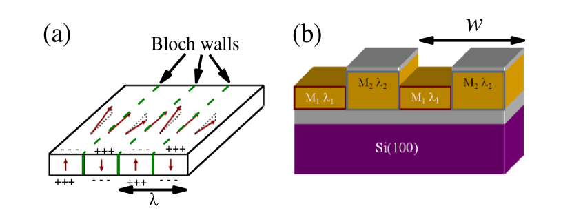
Recently, experiments in weak PMA magnetic lateral multilayersaurelio have shown an intrinsic coupling between topological defects occurring within the in-plane and out-of-plane magnetization configurations (1/2 vortices and 1/2 disclinations) that could be of use to control the nucleation of topological defects in the magnetic stripe domain pattern. Briefly, a magnetic lateral multilayer (MLM) is a continuous magnetic film with a lateral modulation of some relevant magnetic property e.g. ,McCord ; lateral exchange biastheis ; theis2 or anisotropy.ingleses ; jafaar PMA lateral multilayers (PMA-MLM) can be fabricated by introducing a periodic thickness modulationaurelio through a nanostructuration process since the equilibrium stripe domain configuration is very sensitive to thickness variations.huber Lateral changes in sample thickness impose lateral changes in the period of magnetic stripe domains , in the amplitude of the out of plane oscillation and, also, in the average in-plane magnetization component (see sketch in Fig. 1(b)). Therefore, the continuous film breaks up in a set of linear parallel regions with different equilibrium magnetic stripe domain configurations coupled through magnetostatic and exchange interaction to their neighbors. Then, in the same way as the periodic magnetic stripe domain pattern in a continuous film is equivalent to a 2D crystal, the configuration of magnetic stripe domains in a PMA-MLM can be considered analogous to a strained superlattice made up of alternating layers of material with different lattice parameter.strained ; strained2 Thus, ”misfit” between magnetic stripe domains at the different thickness regions becomes an essential parameter to understand the physics of this system. It has been shownaurelio that the consequences of the PMA-MLM fabrication process are to create an in-plane shape anisotropy and, also, to introduce ”edges” within the continuous layer in which topological defects could be nucleated (e.g. 1/2 vortices in the in-plane magnetization or grain boundaries within the magnetic stripe pattern). A good control of the essential parameters needed for nucleation of these topological defects would open the route to understand defect interactions on an individual basis (in contrast with previous statistical studies in disordered patternsstripes1 ; asciutto ; defeo ; huang ; saratz ; venus ) and, also, to study the physics of nucleation and propagation of the observed fractional topological defects (coupled 1/2 disclination -1/2 vortex) which is interesting for magnetic logic devices.parkin ; parkin_new However, in ref. aurelio, , the controlled nucleation of topological defects was only observed under specific geometrical parameters and magnetic history conditions.
In this work, we have studied magnetization reversal processes of weak PMA-MLM’s as a function of nanostructure geometry in order to establish the conditions needed for topological defect nucleation within their magnetic stripe domain patterns. First, we have performed a detailed characterization of the magnetic domain configuration of the PMA-MLM’s during magnetization reversal for different in-plane field orientations and different values of the lateral multilayer period. Then, an analytical model is proposed that takes into account magnetostatic, exchange and misfit interactions between the different patterned regions together with the coupling between in-plane and out-of-plane magnetization components. Finally, the interplay between these different factors has been analyzed as a function of PMA-MLM geometrical parameters in order to determine the most favorable magnetization reversal regimes for controlled nucleation of grain boundaries and disclinations within the magnetic stripe domain configuration.
II EXPERIMENTAL
Amorphous 80 nm NdCo5 alloy films have been grown by co-sputtering from pure Nd and Co targets on 10 nm Al/Si(100) substrates, and protected from oxidation with a 3 nm Al capping layer.cid At room temperature, the saturation magnetization is emu/cm3 and the perpendicular anisotropy constant is erg/cm3,cid so that implying that the Nd-Co films can be considered within the weak PMA regime. The continuous films also present a small in-plane uniaxial anisotropy induced by the cosputtering process.fernando_jap Then, several e-beam lithography, lift-off and ion beam etching processes have been performed in order to create the desired thickness modulation over an extended sample area.aureliojpd The result is a set of m m Nd-Co squares with alternate linear regions of thickness nm and nm, width and lateral period . The patterned grooves are parallel to one of the square sides, as sketched in Fig. 1(b) and, also, to the growth induced easy axis. Due to the thickness dependence of stripe period and in-plane magnetization they will take different values in the different thickness film regions created by the grooved topography. In the following we will refer to the period of magnetic stripe domains and in-plane magnetization component in the thin and thick regions as , and , , respectively. A series of samples with 0.5, 1, 1.4 and 2 m has been fabricated on the same substrate, in order to analyze the different magnetization reversal regimes as a function of sample geometry. In the following, they will be referred to as PMA-MLM() with the lateral period in m. Flat m Nd-Co squares of thickness nm and nm have also been defined near the nanostructured squares for control purposes.
The magnetic properties of the PMA-MLM’s have been characterized by focused Kerr magnetometry using a NanoMOKE2® system in the longitudinal Kerr configuration to obtain the in-plane hysteresis loops. Stripe domain configuration during magnetization reversal has been measured by Magnetic Force Microscopy (MFM) with a Nanotec system that allows us to apply in-plane variable fields up to 1 kOe.aurelio Domain structure for the in-plane magnetization component has been obtained with a high resolution Kerr microscope from Evico Magnetics Gmbh in a longitudinal Kerr effect configuration.
III MAGNETIC CHARACTERIZATION OF WEAK PMA MAGNETIC LATERAL MULTILAYERS
The characterization of stripe domain configuration in PMA-MLM’s has been performed using two different in-plane applied field orientations: first, with parallel to the patterned grooves (easy axis) and, then, with perpendicular to them (hard axis). The first one, easy axis magnetization reversal, will allow us to obtain the basic magnetic behavior of the patterned sample in a simple geometrical configuration in which in-plane magnetization reversal occurs mainly by domain wall motion. The second one, hard axis magnetization reversal, favors rotation processes of the in-plane magnetization component. This results in more complex stripe domain configurations that will allow us to control the nucleation of topological defects within the system.

III.1 Easy axis magnetization reversal
Figure 2 shows the in-plane easy axis hysteresis loops of two PMA-MLM’s in comparison with reference flat squares of thicknesses 50 nm and 80 nm (i.e. equivalent to the thick and thin regions in the MLM’s). All the loops present qualitatively the same transcritical shape, typical of weak PMA materials, with a reduced remanent magnetization followed by an almost linear approach to saturation as the magnetization rotates within the stripe domains towards the in-plane applied field direction.huber ; loop The main differences appear in the remanent magnetization and coercivity values: the thicker 80 nm flat square shows the lowest and largest = 260 Oe, whereas the thinner 50 nm flat square displays the largest and smallest 80 Oe, which is the trend expected from the thickness dependence of these parameters in weak PMA films.fernando_jap The two MLM’s present an intermediate behavior with and 160 Oe. This could be taken, as a first approach, as an indication that the effect of patterning is equivalent to creating an intermediate effective thickness in between and .
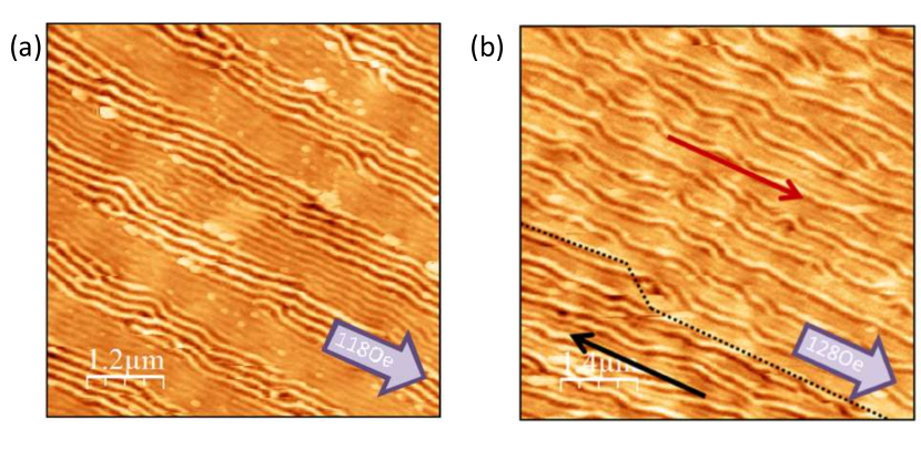
However, the detailed MFM characterization of PMA-MLM(1.4) and PMA-MLM(0.5) reveals a clear influence of the lateral multilayer structure in stripe domain configuration. Figures 3(a-b) are 6 m 6m MFM images of PMA-MLM(1.4) and PMA-MLM(0.5), respectively, taken after saturating them with an in-plane kOe parallel to the nanostructured lines and, then, applying a positive field along the same direction, close to the coercivity. They display the typical stripe domain pattern of weak PMA films aligned with the last saturating field orientation.field The effect of thickness modulation can be seen in the different magnetic stripe periods measured at the thin and thick regionsaurelio with nm and nm for PMA-MLM(1.4), while nm and nm for PMA-MLM(0.5). It is interesting to note that, in this second case, values are comparable to m, the PMA-MLM period, so that only a couple of stripe domains fit within each nanostructured line.
A detailed characterization by Kerr microscopy and MFM reveals qualitative changes in the easy axis magnetization reversal process as the lateral multilayer period is reduced as shown in ref. Supplemental, : in the sample with a larger lateral period m, the effect of patterning is to separate the sample into a set of independent linear regions that switch by the propagation of head-to-head domain walls along them whereas in the sample with the smaller lateral period m, coupling between the different regions dominates and magnetization reversal is more coherent.
III.2 Hard axis magnetization reversal

The behavior of PMA-MLM’s is much more complex when a magnetic field is applied in-plane and perpendicular to the nanostructured lines, and very interesting confined labyrinthine configurations appear within the stripe domain pattern due to the competition between the different anisotropy terms acting on the system. Figure 4 shows several pairs of MFM images taken along a hard axis magnetization reversal process in the different PMA-MLM’s studied in this work. The samples have been saturated first with kOe applied in-plane perpendicular to the patterned lines; then, the field has been reduced to zero (Figs. 4(a-d)); and, finally, it has been increased up to Oe, corresponding approximately to the hard axis coercivity (Figs. 4(e-h)).
All the samples present a similar remanent stripe domain configuration (Figs. 4(a-d)): stripes at the thick regions remain perpendicular to the lines (i.e. along the direction of the last saturating field, as is the usual case in PMA materials due to rotatable anisotropy) but stripes at the thin regions have rotated away from the field direction towards the in-plane easy axis defined by the shape anisotropy created by the artificial thickness modulation. It can be seen that a number of ”misfit” dislocations have been generated at the interfaces (see insets in Figs. 4(a-b)). Due to the differences in equilibrium and stripe orientation in thick and thin regions, stripe periods projected along the interface are also different (see sketch in Fig. 4(c)). Thus, there are extra stripes that terminate on the interface and misfit dislocations are created. Actually, since this happens on a periodic basis, the array of equispaced misfit dislocations can be considered analogous to a low angle grain boundary within the magnetic stripe pattern.
Then, upon applying a reverse perpendicular magnetic field (Figs. 4(e-g)), the rotation process continues within the thin regions until stripe domains become aligned to the nanostructured lines. However, in the PMA-MLM’s with m, stripe domains within the thick regions are still perpendicular to the nanostructured lines so that a set of 900 boundaries has been induced within the magnetic stripe domain pattern of these PMA-MLM. The configuration of these boundaries is quite different from the low angle boundaries observed in the remanent MFM images. The 900 boundaries are decorated by high Burgers vectors dislocations and dissociated 1/2 disclination pairs. Sketches of these topological defects are shown in the insets of Fig. 4(e) for a dislocation with Burgers vector modulus ) and of Fig. 4(f) for a dissociated disclination pair made up of a +1/2 disclination (”dead end”) and a -1/2 disclination (”branch”) that is equivalent to a dislocation with . The typical size of the observed disclination pairs is in the range to . These higher energy topological defects are needed to relieve the large mismatch in between the projected stripe periods at both sides of the boundary due to their almost perpendicular orientation.huang It is interesting to mention that it has been shown that +1/2 disclinations in the magnetic stripe domain pattern are coupled to half vortices in the the closure domain structure for in-plane magnetization, that appears along the magnetization reversal process of the thick lines.aurelio
Finally, it must be noted that a different behavior is found in the stripe domain configuration at coercivity for PMA-MLM(0.5) (Fig.4(h)): the whole stripe domain pattern in both thin and thick regions has rotated away from the applied field direction and is now aligned with the nanostructured lines. Thus, the stripe configuration becomes much simpler without the high angle boundaries present in the larger lateral period MLM’s.
These different behaviors as a function of lateral multilayer period can be seen in more detail in Fig. 5 in which the field dependence of stripe domain orientation relative to the patterned lines is shown for PMA-MLM(1.4) and PMA-MLM(0.5) during a hard axis hysteresis loop (squares and circles correspond to stripes in the thin and thick regions respectively). The angular orientation data have been extracted from the Fast Fourier Transforms (FFT) of a series of consecutive MFM images taken during the hard axis magnetization reversal process. Briefly, topography images recorded simultaneously with the MFM signal are used as a mask to divide each image in two, corresponding to the thin and thick regions. Then, the FFT of each image is used to obtain the angular orientation of stripe patterns within each kind of patterned lines in a precise way.aurelio For the PMA-MLM with wider lateral multilayer period (Fig. 5(a)), stripe domains in the thin regions start close to the negative perpendicular orientation at negative fields (which corresponds to the saturated state for in-plane magnetization in this hard axis loop) and, then, perform a continuous rotation towards the positive perpendicular direction as the hard axis field intensity increases. These rotations within the stripe pattern are directly linked to the rotation that in-plane magnetization performs under the applied field torque.aurelio It is interesting to note the small overshoot that appears in this rotation process up to before the stripe domain orientation stabilizes close to for large positive hard axis fields, which is the typical behavior in Stoner-Wolfarth rotation processes under an applied field slightly misaligned with the uniaxial anisotropy hard axis (by here). At the same time, stripes in the thick regions retain their original perpendicular orientation during the whole measured field range (except for a possible indetermination). On the other hand, for PMA-MLM(0.5) (Fig. 5(b)), both thin and thick regions start close to negative saturation (i.e. close to ) at negative fields but with a 300 angular difference. Then, as the positive hard axis field increases, stripes in both kinds of regions begin to rotate towards the easy axis, reducing the angular distance between them. Once they reach , the stripe domains in the whole sample become coupled and rotate in unison for the rest of the hard axis hysteresis loop until they reach the positive saturation orientation .

We may summarize the results of the MFM characterization in two points: first, the nucleation of high angle grain boundaries within the magnetic stripe domain pattern occurs mainly along hard axis magnetization reversal processes. In this geometry, rotation of the in-plane magnetization component becomes the preferred magnetization reversal mode in the thin regions. Due to the coupling between in-plane magnetization and stripe domains, the hard axis field acts as a handle to rotate the magnetic stripe domains in selected areas. Thus, grain boundaries are nucleated within the magnetic stripe pattern at the limit between different thickness regions. Second, in the PMA-MLM’s with larger lateral period m, grain boundary angle increases up to at the hard axis coercivity and 1/2 disclination pairs are observed. A more coherent behavior appears in PMA-MLM(0.5) both along the easy axis and hard axis magnetization reversal processes. This indicates the stronger role of coupling between neighboring lines as the structural period is reduced down to values comparable to the magnetic stripe period .
IV ANALYTICAL MODEL OF WEAK PMA MAGNETIC LATERAL MULTILAYERS
IV.1 Analytical model
The magnetic characterization of PMA-MLM’s has shown different possibilities to control stripe domain configuration making use of the coupling between in-plane magnetization and stripe patterns in weak PMA films. Now, in order to understand the observed experimental conditions for topological defect nucleation and their dependence on lateral multilayer geometrical parameters, we must consider the interplay between the different energy terms involved in the system.
A first approach to analyze the magnetization rotation in the thin regions during a hard axis reversal process in the larger period PMA-MLM’s can be made using a simplified model for in-plane magnetized MLM’s.aurelio ; lateral In this case, only dipolar and Zeeman energy terms related to in-plane magnetization components are considered ( in the thin lines and in the thick lines): the effective shape anisotropy created by the flux discontinuities that appear at the interface between thin and thick lines due to the lateral modulation of the in-plane magnetization,lateral and the Zeeman energy of , assuming that is fixed at . In this framework, the energy density at the thin lines for oriented at relative to the lines and at may be written as:
| (1) |
with the demagnetizing factor perpendicular to the lines.
However, this simple model is not enough either to capture the physics of the lateral period dependence of the magnetic behavior observed in section III nor to give information about the fabrication parameters needed to create variable angle boundaries within the stripe domain pattern of PMA-MLM’s. A more complete analytical model should also take into account the energy density associated to the stripe domain pattern , exchange and magnetostatic energy terms associated to in-plane magnetization components , and the coupling between in-plane and out-of plane magnetization components, that takes the form of a rotatable anisotropy.
Regarding , it has been shown that the magnetic energy of the stripe domain pattern can be written as the effective elastic energyabanov of a 2D crystal in terms of the deformations relative to the equilibrium periodic stripe domain configuration at a given field. Within this framework, PMA-MLM’s can be considered as the 2D equivalent of strained superlattices since their stripe domain pattern is composed of alternating regions with different equilibrium stripe period, .aurelio Then, we may write their effective elastic energy asstrained
| (2) |
where is the effective bulk elastic modulus of the stripe domain pattern within each region; is the elastic strain in region due to the difference between the equilibrium and its actual value so that ; finally, stands for the energy of the grain boundaries between stripe domains in thin and thick regions. depends on the misfit strain between the stripe domain patterns at both sides of the boundary,
| (3) |
since is the stripe pattern period at each region, projected along the grain boundary plane. For small enough , the grain boundary can be considered as an array of equispaced misfit dislocations with Burgers vector modulus located at distance (see sketch in Fig. 4(c)). Then,
| (4) |
with the energy of a single dislocation given by , where is the dislocation energy coefficient and is a constant.strained
The energy for in-plane energy magnetization components in a MLM can be written aslateral
| (5) |
which generalizes eq. (1) to take into account , the energy of the domain wall that appears in between thin and thick regions due to the different in-plane magnetization orientations. In general, is a function of . We have taken, as a first approach, , considering that and are constant throughout each patterned line so that exchange takes place primarily at the interfaces.huber
Finally, coupling between in-plane and out-of-plane magnetization is given by ”rotatable magnetic” anisotropy. Briefly, when a PMA film has been saturated in plane, and the applied field intensity decreases along a hysteresis loop, stripe domains are nucleated as a weak out-of-plane oscillation parallel to in-plane magnetization and, correspondingly to the applied field direction. As goes down to zero, the amplitude of this out-of-plane oscillation increases and the in-plane magnetization component is reduced. As a consequence, possible in-plane magnetization rotations are hindered by the need to reorient the whole stripe pattern and a ”pseudo uniaxial” in-plane anisotropy is created in the system. The last saturating field direction becomes an in-plane easy axis with its corresponding anisotropy constant , that can be estimated asluis
| (6) |
where are the Bessel functions of the first kind and integral order , is the stripe pattern period, is the film thickness and is given by the implicit condition . has a magnetostatic origin, thus it is proportional . It is zero for , i.e. and no stripe pattern, and increases as decreases, as shown in Fig. 6(a).
We will begin our analysis by considering only the interplay between rotatable anisotropy (that accounts for the coupling between in-plane and out-of-plane magnetization components in weak PMA materials) and shape anisotropy (that accounts for the effect of lateral patterning on in plane magnetization) in section IV.B. These two terms have a common magnetostatic origin and it will be shown that their competition captures the essential physics to understand the nucleation of grain boundaries within the magnetic stripe domain patterns of the MLM. Then, in section IV.C, we will turn our attention to the remaining energy terms related with in plane domain walls and grain boundaries in the stripe pattern. This, will allow us to understand the transition to the strongly coupled regime observed for PMA-MLM(0.5). All these analysis will be performed considering that the system is at remanence for simplicity.
IV.2 Nucleation of grain boundaries within the stripe pattern: Competition between shape and rotatable anisotropies
As a starting point to study the competition between rotatable anisotropy and shape anisotropy it is interesting to consider the behavior of a single weak PMA infinite nanowire of thickness and width . In this simplified case, reduces only to shape anisotropy energy and eq. (5) becomes
| (7) |
where is the shape anisotropy constant and .Nx increases as a function of and is enhanced as nanowire width decreases, as shown in Fig. 6(a).

The effect of shape anisotropy on the system is to rotate towards the wire axis. However, for a wire magnetized perpendicular to the wire axis, would compete with the rotatable anisotropy that tends to keep the stripe pattern (and its associated ) in its original orientation: for small and large , should dominate the nanowire magnetic behavior and no rotations should appear during a hard axis hysteresis loop. On the contrary, a regime dominated by would appear for large enough and/or small nanowire width in which stripe domains rotate during hard axis magnetization reversal following until they become aligned with the nanowire axis at coercivity. The crossover between these two regimes can be calculated, as a first approximation, by the condition . This defines a boundary within the vs. plane, as indicated by the solid line in Fig. 6(b). Stripe domain rotation will be favored in nanowires with and above this line, whereas stripe domains should remain fixed by for wires with parameters below it.
This single wire diagram can be used as a starting point to model the behavior of PMA-MLM’s as two sets of infinite parallel nanowires of width , alternating thicknesses and and in-plane magnetizations and . Magnetostatic coupling between the two sets of nanowires due to the flux discontinuities that appear at the interfaces modifies eq.(7), giving
| (8) |
We have calculated again the crossover condition as , considering that the competition between both terms occurs when the system is at the initial hard axis saturated configuration with and perpendicular to the wires axis. Then, the effect of magnetostatic coupling is to move the crossover lines for the PMA-MLM’s to higher values, as shown in Fig. 6(b), since it reduces .
Now, we may use this vs. diagrams to predict the nucleation of grain boundaries within the stripe pattern of PMA-MLM’s: for a given value of , and should lie at different sides of the crossover line between and dominated regimes so that stripes in thin regions rotate while stripes in the thick regions remain fixed. We can take, as an example, the remanent magnetization values of the control films with nm and nm, indicated by filled and hollow squares in Fig.6(b) and compare them with the observed behavior in the PMA-MLM’s of Fig.4. is well within the ”non-rotating” region, whereas lies close to the crossover line calculated for changing from one regime to the other at m. This is qualitatively in agreement with the observation of ”grain boundaries” in the PMA-MLM’s with in the m range. However, it underestimates the maximum lateral period compatible with ”grain boundary nucleation”, probably because the start of the stripe domain rotation process occurs well before remanence (i.e at larger values).
IV.3 Coupling effects in PMA-MLM’s
One of the limitations of the analysis made in the previous subsection is that it does not predict the strongly coupled regime observed in PMA-MLM(0.5), in which the stripe pattern in the whole sample rotates in unison. Thus, other sources of coupling in between the different patterned regions must be considered in addition to magnetostatic coupling.
There are three energy terms in eqs. (2) and (5) that scale as and should dominate the behavior of the system in the small limit: grain boundary energy within the magnetic stripe pattern , domain wall energy within the in-plane magnetization configuration and magnetostatic coupling through the width dependence of . These different terms have been calculated as a function of lateral multilayer period, as shown in Fig. 7, using the experimental and values obtained from the MFM images taken at remanence during a hard axis loop (Figs.4(a)-(d)). We have chosen to study the evolution of the system in the remanent state because of two reasons: first, Zeeman energy terms need not to be considered, which simplifies the analysis; second, the MFM images show that at this state, grain boundaries in between thin and thick regions are composed of a simple misfit dislocation array so that eq. (4) can be used to estimate .
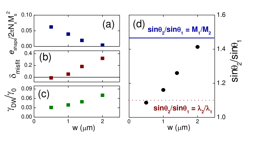
The first thing that can be noticed in Fig.7(a) is that, starting from PMA-MLM(2), the magnetostatic energy term, normalized by , increases as is reduced. On the other hand, both , which is proportional to , and decrease as the small region is approached (Figs. 7(b-c)). This implies that the system prefers to minimize these last two interaction terms as is reduced at the expense of adopting a less favorable configuration for the magnetostatic energy term.
This can be seen in more detail in Fig. 7(d) in which we have plotted the ratio vs. in order to compare it with the conditions that minimize each of these interaction terms. First, the magnetostatic energy term will be zero if , i.e. , which is calculated using the remanent magnetization values of the control films with thickness and . Second, grain boundary energy should be minimum if , which corresponds to . Finally, exchange energy will be minimized if so that . It is seen that whereas PMA-MLM(2) is close to fulfilling the magnetostatic coupling minimum conditions, the ratio departs towards lower values as soon as is reduced. Then, when the strongly coupled regime of PMA-MLM(0.5) is reached, the condition to minimize is fulfilled. This is probably a size effect since patterned line width m is comparable to stripe domain period m. Thus, misfit dislocations cannot be accommodated within the PMA-MLM and stripe domains at the thin and thick regions become locked in a zero misfit configuration.
IV.4 Geometrical regimes for stripe domain configuration in PMA-MLM’s
The results of the analysis of the different energy terms involved in these PMA-MLM’s show three different regimes as a function of lateral multilayer period.
First, there is a large regime, in which rotatable anisotropy (which is a bulk energy term) dominates and the PMA-MLM’s behave as continuous unpatterned films with their stripe domain patterns oriented along the last saturating field direction independently of its orientation relative. This regime would be favored both for large and small difference between and , i.e. for small thickness modulations, which would explain the absence of rotations found within the stripe patterns of PMA-MLM’s with nm and 0.5 m m in ref. aurelio, .
Second, there is an intermediate regime, in which shape anisotropy induced by the thickness modulation overcomes rotatable anisotropy only in the thin regions and, thus, thin and thick regions switch independently during a hysteresis process. This is the most interesting regime to study topological defects in the magnetic stripe domains, since variable angle grain boundaries and disclinations are nucleated at the interfaces, coupled to domain walls for in-plane magnetization.
Finally, there is a small regime, in which coupling between thin and thick regions becomes strong enough to overcome rotatable anisotropy in the thick patterned lines and the film switches as a whole during the magnetization reversal process, under the effect of the in-plane uniaxial anisotropy induced by the lateral thickness modulation. In this regime, misfit strain within the magnetic stripe domain pattern is minimized. This is related with the similar size of patterned line width m and stripe domain period m. Thus, misfit dislocations and disclination pairs needed to nucleate variable angle grain boundaries in the stripe domain pattern become too large to fit within the interfaces between thin and thick regions since their size is of the order - , as observed in the MFM characterization.
In summary, the previous analysis has shown that the essential physical ingredients needed for controlled nucleation of topological defects within the magnetic stripe domain configuration are: first, the existence of localized ”misfit strains” in the stripe pattern created by the local changes of due to the nanofabricated thickness modulation; second, the competition between rotatable anisotropy and shape anisotropy induced by nanopatterning that allows local rotations of stripe domains due to their coupling with and, third, the use of large enough lateral geometrical features in comparison with the relevant topological defects to avoid size effects that would inhibit defect nucleation.
V CONCLUSIONS
In summary, the different regimes of magnetization reversal in weak PMA-MLM’s have been studied as a function of lateral multilayer period , both experimentally and with the aid of an analytical model, in order to establish the conditions for controlled topological defect nucleation within their magnetic stripe patterns. At m, lateral patterning induces different reversal processes in the thin and thick regions so that they switch independently during easy axis and hard axis hysteresis loops: domain walls are created within the in-plane magnetization configuration coupled to variable angle grain boundaries and disclinations within the stripe domain patterns. This process is driven by the interplay between shape anisotropy induced by the periodic thickness modulation and the different values of rotatable anisotropy in the thin and thick regions. On the other hand, as the lateral period is reduced down to m a strongly coupled regime is found in which the PMA-MLM switches as a whole and misfit strain within the magnetic stripe pattern is minimized.
Acknowledgements.
Work supported by Spanish MICINN under grant FIS2008-06249. R. M. and N. S. acknowledge support from UPV/EHU UFI11/23 and Basque Country Government grant Etorek SE11-304. A.H-R. acknowledges support from FCT of Portugal grant (SFRH/BPD/90471/2012).References
-
(1)
-
minor A. Berger, S. Mangin, J. McCord, O. Hellwig, and E. E. Fullerton, Phys. Rev. B 82, 104423 (2010).
- (2) E. Sallica Leva, R. C. Valente, F. Martinez Tabares, M. Vasquez Mansilla, S. Roshdestwensky and A. Butera, Phys. Rev. B 82, 144410 (2010).
-
(3)
P. Molho, J. L. Porteseil, Y. Souche, J. Gouzerh
and J. C. S. Levy, J. Appl. Phys. 61, 4188 (1987).
- (4) M. Hehn, K. Ounadjela, J. P. Bucher, F. Rousseaux, D. Decanini, B. Bartenlian, and C. Chappert, Science 272, 1782 (1996).
- (5) O. Portmann, A. Vaterlaus and D. Pescia, Nature 422, 701 (2003)
- (6) M. Seul and D. Andelman, Science 267, 478 (1995).
- (7) M. Seul and R. Wolfe, Phys. Rev. A 46, 7519 (1992).
- (8) S. Foss, C. Merton, R. Proksch, G. Skidmore, J. Schmidt, E. D. Dahlberg, T. Pokhil and Y. T. Cheng, J. Magn. Magn. Mat. 190, 60 (1998).
- (9) Z. F. Huang and J. Viñals, Phys. Rev. E 75, 056202 (2007).
- (10) I. Makhfudz, B. Krüger and O. Tchernyshyov, Phys. Rev. Lett. 109, 217201 (2012).
- (11) X. Yu, M. Mostovoy, Y. Tokunaga, W. Zhang, K. Kimoto, Y. Matsui, Y. Kaneko, N. Nagaosa, and Y. Tokura, PNAS 109, 8856 (2012).
- (12) N. Abu-Libdeh and D. Venus, Phys. Rev. B 84, 094428 (2011).
- (13) E. Asciutto, C. Roland and C. Sagui, Phys. Rev. E 72, 021504 (2005).
- (14) M. P. DeFeo and M. Marchevsky, Phys. Rev. B 73, 184409 (2006).
- (15) N. Saratz, A. Lichtenberger, O. Portmann, U. Ramsperger, A. Vindigni and D. Pescia, Phys. Rev. Lett. 104, 077203 (2010).
- (16) O. Tchernyshyov and G. W. Chern, Phys. Rev. Lett. 95, 197204 (2005).
- (17) G. Rodríguez-Rodríguez, H. Rubio, M. Vélez, A. Pérez-Junquera, J. V. Anguita, J. I. Martín, and J. M. Alameda, Phys. Rev. B 78, 174417 (2008).
- (18) S. Glathe, M. Zeisberger, U. Hübner, R. Mattheis, and D. V. Berkov, Phys. Rev. B 81, 020412 (2010).
- (19) R. K. Dumas, D. A. Gilbert, N. Eibagi, and K. Liu, Phys. Rev. B 83, 060415 (2011).
- (20) L. Thomas, M. Hayashi, R. Moriya, C. Rettner and S. Parkin, Nature Comm. 3, 810 (2012).
- (21) A. Hubert and R. Schäfer, Magnetic Domains, (Springer-Verlag, Berlin, 1998).
- (22) R. Brucas, H. Hafermann, M.I. Katsnelson, I. L. Soroka, O. Eriksson and B. Hjorvarsson, Phys. Rev. B 69, 064411 (2004).
- (23) D. Clarke, O. A. Tretiakov and O. Tchernyshyov, Phys. Rev. B 75, 174433 (2007).
- (24) H. Fujiwara, Y. Sugita, and N. Saito, Appl. Phys. Lett. 4, 199 (1964).
- (25) L. M. Álvarez-Prado, G. T. Pérez, R. Morales, F. H. Salas, and J. M. Alameda, Phys. Rev. B 56, 3306 (1997).
- (26) A. Hierro-Rodriguez, R. Cid, M. Vélez, G. Rodriguez-Rodriguez, J. I. Martín, L. M. Álvarez-Prado, and J. M. Alameda, Phys. Rev. Lett. 109, 117202 (2012).
- (27) J. McCord, L. Schultz and J. Fassbender, Adv. Mat. 20, 2090 (2008).
- (28) N. Martin, I. Mönch, R. Schäfer, J. Fassbender, L. Schultz and J. McCord, Phys. Rev. B 83, 174423 (2011).
- (29) K. Theis-Bröhl, M. Wolff, A. Westphalen, H. Zabel, J. McCord, V. Höink, J. Schmalhorst, G. Reiss, T. Weis, D. Engel, A. Ehresmann, U. Rücker and B. P. Toperverg, Phys. Rev. B 73, 174408 (2006).
- (30) C. Hamann, J. McCord, L. Schultz, B. P. Toperverg, K. Theis-Bröhl, M. Wolff, R. Kaltofen and I. Mönch, Phys. Rev. B 81, 024420 (2010).
- (31) S. P. Li, W. S. Lew, J. A. C. Bland, L. Lopez-Diaz, C. A. F. Vaz, M. Natali, and Y. Chen, Phys. Rev. Lett. 88, 087202 (2002).
- (32) M. Jaafar, R. Sanz, J. McCord, J. Jensen, R. Schäfer, M. Vazquez, and A. Asenjo, Phys. Rev. B 83, 094422 (2011).
- (33) K. Wiesauer and G. Springholz, Phys. Rev. B 69, 245313 (2004).
- (34) Th. Kehagias, Ph. Komninou, G. Nouet, P. Ruterana, and Th. Karakostas, Phys. Rev. B 64, 195329 (2001).
- (35) A. Pushp, T. Phung, C. Rettner, B. P. Hughes, S.-H. Yang, L. Thomas and S. S. P. Parkin, Nature Phys. 9, 505 (2013).
- (36) R. Cid, G. Rodriguez-Rodriguez, L. M. Alvarez-Prado, J. Diaz and J. M. Alameda, J. Magn. Magn. Mat. 316, e446 (2007).
- (37) F. Valdés-Bango, F.J. Garcia Alonso, G. Rodriguez-Rodriguez, L. Moran Fernandez, A. Anillo, L. Ruiz-Valdepeñas, E. Navarro, J.L. Vicent, M. Velez, J.I. Martin and J.M. Alameda, J. Appl. Phys. 112, 083914 (2012).
- (38) A. Hierro-Rodriguez G. Rodriguez-Rodriguez, J. M. Teixeira, G. N. Kakazei, J. B. Sousa, M Velez, J. I. Martin, L. M. Alvarez-Prado and J. M. Alameda, J. Phys. D: Appl. Phys. 46, 345001 (2013).
- (39) See Supplemental Material for a detailed Kerr microscopy and MFM characterization of easy axis magnetization reversal processes of PMA-MLM’s.
- (40) A. Aharoni, L. Pust and M. Kief, J. Appl. Phys. 87, 6564 (2000).
- (41) Ar. Abanov, V. Kalatsky, V. L. Pokrovsky and W. M. Saslow, Phys. Rev. B 51, 1023 (1995).
- (4) M. Hehn, K. Ounadjela, J. P. Bucher, F. Rousseaux, D. Decanini, B. Bartenlian, and C. Chappert, Science 272, 1782 (1996).
-