Geometry-induced Casimir suspension of oblate bodies in fluids
Abstract
We predict that a low-permittivity oblate body (disk-shaped object) above a thin metal substrate (plate with a hole) immersed in a fluid of intermediate permittivity will experience a meta-stable equilibrium (restoring force) near the center of the hole. Stability is the result of a geometry-induced transition in the sign of the force, from repulsive to attractive, that occurs as the disk approaches the hole—in planar or nearly-planar geometries, the same material combination yields a repulsive force at all separations in accordance with the Dzyaloshinskiĭ–Lifshitz–Pitaevskiĭ condition of fluid-induced repulsion between planar bodies Dzyaloshinskiĭ et al. (1961). We explore the stability of the system with respect to rotations and lateral translations of the disks, and demonstrate interesting transitions (bifurcations) in the rotational stability of the disks as a function of their size. Finally, we consider the reciprocal situation in which the disk–plate materials are interchanged, and find that in this case the system also exhibits meta-stability. The forces in the system are sufficiently large to be observed in experiments and should enable measurements based on the diffusion dynamics of the suspended bodies.
Casimir forces arising from quantum/thermal fluctuations of charges are becoming increasingly important in nano- and micro-scale systems Casimir (1948); Milton (2004); Lamoreaux (2007); Genet et al. (2008); Bordag et al. (2009); Klimchitskaya et al. (2009); Rodriguez et al. (2011); Dalvit et al. (2011), where the usually attractive nature of the force leads to unwanted effects such as stiction Rodriguez et al. (2011). Recent theoretical developments have made it possible to study the influence of geometry and materials on these interactions Johnson (2011); Rodriguez et al. (2011); for instance, geometry effects alone can lead to unusual behaviors, including non-monotonic and/or repulsive forces between vacuum-separated bodies Rodriguez et al. (2007); Rodriguez-Lopez et al. (2009); Levin et al. (2010). For planar geometries, one way to obtain repulsion is to employ fluids Israelachvili (1991); Dzyaloshinskiĭ et al. (1961); Parsegian (2006). Dzyaloshinskiĭ et. al. showed decades ago that two planar bodies of permittivities immersed in a fluid of permittivity , satisfying will repel one another Dzyaloshinskiĭ et al. (1961), an effect that has also been observed in experiments Feiler et al. (2008); Munday et al. (2009). Based on that prediction, one might ask whether the Dzyaloshinskiĭ–Lifshitz–Pitaevskiĭ (DLP) condition alone suffices to obtain repulsion regardless of geometry. In this letter, we exploit a recently developed numerical method for computing Casimir interactions between arbitrary bodies Reid et al. (2011) to answer this question in the negative. Specifically, we show that the Casimir potential between an oblate body (a disk-shaped object) and a thin metal substrate (a plate with a hole) immersed in a fluid satisfying the DLP condition exhibits a meta-stable equilibrium at the center of the hole, creating a “Casimir trap” for the disk.
Although Casimir suspensions are impossible for vacuum-separated bodies (irrespective of geometry) Kenneth and Klich (2006); Rahi et al. (2010), they can arise in fluids satisfying the DLP condition Rodriguez et al. (2008); McCauley et al. (2010); Rodriguez et al. (2010). The approach described here differs from previous work in that it does not rely on material dispersion Rodriguez et al. (2010) or the presence of external forces (e.g. gravity McCauley et al. (2010)), nor does it require bodies to be enclosed inside one another Rodriguez et al. (2008); Rahi and Zaheer (2010), but instead stems from the anomalous behavior of electromagnetic fields in this particular geometry (shown schematically in Fig. 1). In recent work Levin et al. (2010), we exploited a similar geometric effect to demonstrate the possibility of switching the sign of the Casimir force between two vacuum-separated bodies—a small, metallic, prolate body (thin needle) centered above a metal plate with a hole—from attractive to repulsive. That phenomenon was explained via a simple symmetry argument Levin et al. (2010): because the fields of a needle in vacuum behave like those of a dipole oriented along its symmetry axis, its interaction with a plate decreases as the needle reaches the center of the hole (at which point the field lines become orthogonal to the plate). The same symmetry argument (in conjunction with a more sophisticated dipole model) is employed here to show that in water, the interaction between a small Polutetraflouroethylene (PTFE) body and a thin gold (Au) plate with a hole can be switched from repulsive to attractive near the vicinity of the hole. To our surprise, however, the interesting geometry in this case is not a needle but rather an oblate body (thin disk), a consequence of the flipped polarization-response of the disk in the fluid. We quantify deviations from dipole-like behavior by comparing our Casimir predictions against a corresponding Casimir–Polder (CP) model in which the disk is modelled as a dipole of equivalent polarizability, and show that finite-size effects can lead to significant qualitative and quantitative deviations for large disks and small separations. Interestingly, despite these deviations, we find that the desired geometric effects persist even for large disks (with diameters hole size), leading to much larger forces than those predicted in the vacuum case. Moreover, unlike the vacuum case (in which the needle must be anchored to a static surface Levin et al. (2010); McCauley et al. (2011)), here the disks are stable with respect to rotations and/or lateral translations, and are therefore free to move subject to Brownian motion. This enables exploration of this phenomenon through a broader set of experimental techniques, e.g. measurements based on total-internal reflection microscopy or diffusion dynamics. Finally, we consider the “reciprocal” situation involving a Au disk above a PTFE plate, and find that in that case one also obtains a meta-stable equilibrium, albeit with larger geometric anisotropy leading to larger energy barriers.
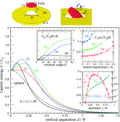
Figure 1 shows the room-temperature Casimir energy between a PTFE disk and a co-axial Au plate immersed in water, as a function of their mutual center–center separation . is normalized by the energy when the two bodies are coplanar () and is plotted for multiple aspect ratios (keeping fixed). The Au dielectric permittivity is obtained from a Drude model with plasma frequency eV and damping constant eV, whereas the PTFE and water permittivities are obtained using the oscillator models described in van Zwol and Palasantzas (2010). This specific material combination was chosen because it satisfies the DLP condition of fluid repulsion between planar bodies—indeed, we find that the force between a finite disk and an unpatterned () plate is repulsive over all and diverges as (not shown). As expected, and in contrast to the unpatterned case, the presence of the hole means that no longer diverges as but instead reaches a finite constant (so long as ). We find that for spheres (dashed black line), nearly-isotropic, or prolate bodies, increases monotonically with decreasing , attaining its peak at as expected. The situation is different for oblate bodies (), in which case peaks at a critical separation (determined by ), below which the force transitions from repulsive to attractive. In particular, instead of the usual unstable equilibrium, we find that the disk exhibits a meta-stable equilibrium at . In order to investigate the full stability of the disk, and its dependence on , the top insets in Fig. 1 show the energy of the system in the co-planar configuration () as a function of rotation and lateral translations of the disk, for multiple . Our results reveal that whenever is either too small or too large, the non-monotonicity in the potential (and corresponding meta-stability) disappears. Specifically, we find that and the corresponding potential barrier vanish as and (not shown in the figure), respectively. Moreover, while the disk is repelled from the edges of the hole irrespective of , its stability with respect to rotations changes drastically with increasing . In particular, beyond , corresponding to , additional unstable and stable equilibria appear at (a finite) and , respectively. For (not shown), corresponding to , the preferred orientation of the disk (the minimum ) changes from (parallel) to (perpendicular). In the perpendicular orientation, the potential barrier and the disk is repelled from the hole.
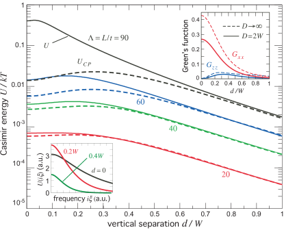
In order to understand the above features as well as the origin of the non-monotonicity in , it is useful to examine the Casimir-energy imaginary-frequency spectrum ) of the system , whose integral (a Matsubara sum at finite temperatures Rodriguez et al. (2011)) yields . The bottom inset of Fig. 2 shows for a representative disk–plate configuration exhibiting non-monotonicity () at multiple separations , and illustrates that non-monotonicity in is present only at small “quasistatic” . In this quasistatic regime, a thin disk immersed in a fluid of larger permittivity will act like a fluctuating dipole oriented mainly along its symmetry axis 111Strictly speaking, the dipole limit requires .. In contrast, the same disk in vacuum will be mainly polarized in the direction transverse its axis of symmetry (as shown below). Since the fields generated by a fluctuating dipole lie mainly along the dipole axis and become orthogonal to the metal plate as , it follows that the disk–plate interaction will weaken in the vicinity of the hole Levin et al. (2010), leading to the behavior above.
In what follows, we quantify the previous argument via a simple model in which the disk is described as a dipole with an effective polarizability, corresponding to the leading-order term of a spherical-harmonic expansion in the scattering formalism Emig et al. (2009). The zero-temperature CP energy between a polarizable particle at position and the plate can be written as Casimir and Polder (1948); Dalvit et al. (2011):
| (1) |
where and are the imaginary-frequency dipole polarizability and Dyadic Green’s function (GF) of the plate in the surrounding medium evaluated at the location of the dipole.
Although the polarizability of a disk of permittivity , diameter , height , and corresponding volume , surrounded by a medium of permittivity , cannot be easily computed analytically, it is nevertheless well approximated by that of a spheroidal body of similar dimensions van de Hulst (1957); Venermo and Sihvola (2005). In that case, the polarizability in the th direction,
| (2) |
is determined by the ratio and depolarization factors, and
| (3) |
where is the eccentricity of the body Venermo and Sihvola (2005).
To qualitatively explain the behavior observed in Fig. 1, it suffices to restrict our analysis to the asymptotic limits of either an elongated “needle” (a prolate body with ) or a flat “disk” (an oblate body with ), in which case
| (4) |
Matters simplify further in the limit of large index contrast ( or ), in which case the CP energies of the needle and disk take the form:
| (5) | ||||
| (6) |
where . In the case of an infinitesimally thin perfect electric conductor (PEC) plate (corresponding to , , and in our geometry) with a hole of size , one can write down an analytical expression for in the non-retarded limit Eberlein and Zietal (2011); Milton et al. (2011). For a dipole centered along the axis of symmetry of the plate, i.e. , one finds that exhibits local minima and maxima at and , respectively, while decreases monotonically with separation Eberlein and Zietal (2011). Both GF components are plotted versus on the top inset of Fig. 2 (dashed lines). It follows from Eq. 5 that a needle will experience a repulsive (attractive) force for () in the regime, as was predicted in Levin et al. (2010), and a repulsive force at all separations in the regime, in agreement with predictions based on the DLP condition. In contrast, however, Eq. 6 predicts that a disk will experience an attractive force at all separations in the regime, and an attractive (repulsive) force for () in the regime, in qualitative agreement with our results above.
In order to incorporate effects coming from the finite size/thickness of the plate, as well as to quantify deviations from the dipole picture that arise in the and limits, we compare our results of Fig. 1 to the corresponding CP potential of the system, obtained via Eq. 1 by assuming a spheroidal particle with polarizability given by Eq. 2 and with computed numerically. As expected, the GFs of the finite Au plate, plotted in the limit on the top inset of Fig. 2 (solid lines), are smaller than those of the semi-infinite PEC plate (due to its smaller surface area), but exhibit the same anomalous behavior. (Away from the quasistatic regime, corresponding to larger , exhibits non-monotonicity but tends to unity, causing the object to appear more isotropic as can be seen from Eq. 2, and leading to the dissapearance of this effect.) Figure 2 shows both and the Casimir energy versus , for multiple values of (with fixed as before), showing agreement at large and small , a regime where the disks behave like ideal (isolated) dipoles. In the opposite limit of large (corresponding to ), the outer and inner surfaces of the disk and plate approach one another (touching as for ), thereby causing the interaction energy to be dominated by proximity effects Dalvit et al. (2011). This transition manifests itself in multiple ways: First, though the CP model predicts a monotonically increasing with increasing , we find instead that in the finite system, reaches a maximum at and then decreases as (red circles on the bottom inset of Fig. 1). Second, while the dipole picture predicts a monotonically increasing (stemming from the linear dependence of the polarizability with the disk volume), the dependence of on exhibits a power-law divergence that scales as , with , in the limit as (green line on the bottom inset of Fig. 1). The same proximity effects are responsible for a dramatic increase in (blue line) with increasing . We note however, that the competition between increasing and decreasing nonmonotonicity eventually skews in favor of the latter causing a peak in as and eventually causing in this limit (not shown in the figure).
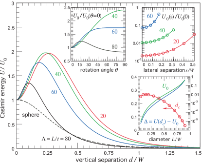
Figure 3 shows the ratio for the same geometry of Fig. 1 but for the “reciprocal” situation where the Au and PTFE materials are interchanged (corresponding to a Au disk above a PTFE plate). As before, the insets explore the stability of the system with respect to rotations and lateral translations of the disk. In this case, the polarizability of the disk is largest along the lateral (–) directions, and hence the relevant equation describing the resulting CP interaction is the top equation of Eq. 6. However, unlike the previous case, here it is the and components of the DGF (and not ) that exhibit non-monotonicity, leading again to a meta-stable equilibrium at , albeit with slightly smaller and significantly larger non-monotonicity for the same . Essentially, the index contrast between the Au disk and the fluid is orders of magnitude larger than for a PTFE disk, leading to larger polarization anisotropies. Unfortunately, the enhanced anisotropy comes at a price: First, the small index contrast between the plate and the fluid results in a smaller , a consequence of the larger contribution of the plate area. Second, the transition in the preferred orientation of the disk from occurs at smaller . The large polarization anisotropy of the Au disk also means that the potential trap is not very sensitive to the disk thickness. Fixing nm and , we find that and as is increased from nm (corresponding to a decrease in from ). On the other hand, we find that is very sensitive to changes in the PTFE plate thickness. Fixing nm and , we find that rapidly as is increased from nm. The situation is reversed in the reciprocal configuration of Fig. 1, in which case the trap is sensitive to the disk thickness and not the plate thickness.
The system described in this work constitutes a promising platform to investigate two unusual geometry-induced Casimir phenomena: a violation of the DLP condition of fluid repulsion between planar bodies, and the stable suspension of two bodies. At room temperature, the resulting “Casimir trap” has a depth on the order of , which, unlike the case of a needle in vacuum Levin et al. (2010), allows for simpler (and more varied) experimental verification of this phenomenon. It could also open new horizons for technological applications where passive suspension is relevant. We believe that even more pronounced effects should arise in other geometries and material configurations. For instance, stronger potential traps might be obtained by designing the shapes of the suspended bodies to exhibit larger polarization anisotropy, a subject of future work.
This work was supported by DARPA Contract No. N66001-09-1-2070-DOD, by the AFOSR Multidisciplinary Research Program of the University Research Initiative (MURI) for Complex and Robust On-chip Nanophotonics, Grant No. FA9550-09-1-0704, and by the U.S. Army Research Office under contracts W911NF-07-D-0004 and W911NF-13-D-0001.
References
- Dzyaloshinskiĭ et al. (1961) I. E. Dzyaloshinskiĭ, E. M. Lifshitz, and L. P. Pitaevskiĭ, Adv. Phys. 10, 165 (1961).
- Casimir (1948) H. B. G. Casimir, Proc. K. Ned. Akad. Wet. 51, 793 (1948).
- Milton (2004) K. A. Milton, J. Phys. A 37, R209 (2004).
- Lamoreaux (2007) S. K. Lamoreaux, Phys. Today 60, 40 (2007).
- Genet et al. (2008) C. Genet, A. Lambrecht, and S. Reynaud, Eur. Phys. J. Special Topics 160, 183 (2008).
- Bordag et al. (2009) M. Bordag, G. L. Klimchitskaya, U. Mohideen, and V. M. Mostapanenko, Advances in the Casimir Effect (Oxford University Press, Oxford, UK, 2009).
- Klimchitskaya et al. (2009) G. L. Klimchitskaya, U. Mohideen, and V. M. Mostapanenko, Rev. Mod. Phys. 81, 1827 (2009).
- Rodriguez et al. (2011) A. W. Rodriguez, F. Capasso, and S. G. Johnson, Nat. Phot. 5, 211 (2011).
- Dalvit et al. (2011) D. A. R. Dalvit, P. Milonni, D. Roberts, and F. da Rosa, eds., Lecture Notes in Physics, vol. 834 (Springer-Verlag, 2011).
- Johnson (2011) S. G. Johnson, in Casimir Physics, edited by D. A. R. Dalvit, P. Milonni, D. Roberts, and F. d. Rosa (Springer–Verlag, 2011), vol. 836 of Lecture Notes in Physics, chap. 6, pp. 175–218.
- Rodriguez et al. (2007) A. Rodriguez, M. Ibanescu, D. Iannuzzi, F. Capasso, J. D. Joannopoulos, and S. G. Johnson, Phys. Rev. Lett. 99, 080401 (2007).
- Rodriguez-Lopez et al. (2009) P. Rodriguez-Lopez, S. J. Rahi, and T. Emig, Phys. Rev. A 80, 022519 (2009).
- Levin et al. (2010) M. Levin, A. P. McCauley, A. W. Rodriguez, M. T. H. Reid, and S. G. Johnson, Phys. Rev. Lett. 105, 090403 (2010).
- Israelachvili (1991) J. N. Israelachvili, Intermolecular and Surface Forces (Academic Press, London, 1991).
- Parsegian (2006) A. V. Parsegian, Van der Waals Forces: A Handbook for Biologists, Chemists, Engineers, and Physicists (Cambridge University Press, NY, 2006).
- Feiler et al. (2008) A. A. Feiler, L. Bergstrom, and M. W. Rutland, Langmuir 24, 2274 (2008).
- Munday et al. (2009) J. Munday, F. Capasso, and V. A. Parsegian, Nature 457, 170 (2009).
- Reid et al. (2011) H. Reid, J. White, and S. G. Johnson, Phys. Rev. A. Rapid. Comm. 84, 010503 (2011).
- Kenneth and Klich (2006) O. Kenneth and I. Klich, Phys. Rev. Lett. 97, 160401 (2006).
- Rahi et al. (2010) S. J. Rahi, M. Kardar, and T. Emig, Phys. Rev. Lett. 105, 070404 (2010).
- Rodriguez et al. (2008) A. W. Rodriguez, J. Munday, D. Davlit, F. Capasso, J. D. Joannopoulos, and S. G. Johnson, Phys. Rev. Lett. 101, 190404 (2008).
- McCauley et al. (2010) A. P. McCauley, A. W. Rodriguez, J. D. Joannopoulos, and S. G. Johnson, Phys. Rev. A 81, 012119 (2010).
- Rodriguez et al. (2010) A. W. Rodriguez, A. P. McCauley, D. Woolf, F. Capasso, J. D. Joannopoulos, and S. G. Johnson, Phys. Rev. Lett. 104, 160402 (2010).
- Rahi and Zaheer (2010) S. J. Rahi and S. Zaheer, Phys. Rev. Lett. 104, 070405 (2010).
- McCauley et al. (2011) A. P. McCauley, A. W. Rodriguez, M. T. H. Reid, and S. e. G. Johnson, arXiv 1105.0404 (2011).
- van Zwol and Palasantzas (2010) P. J. van Zwol and G. Palasantzas, Phys. Rev. A 81, 062502 (2010).
- Eberlein and Zietal (2011) C. Eberlein and R. Zietal, Phys. Rev. A 83, 052514 (2011).
- Emig et al. (2009) T. Emig, N. Graham, L. R. Jaffe, and M. Kardar, Phys. Rev. A 79, 054901 (2009).
- Casimir and Polder (1948) H. B. G. Casimir and D. Polder, Phys. Rev. 13, 360 (1948).
- van de Hulst (1957) H. C. van de Hulst, Light scattering by small particles (Dover Publications, 1957).
- Venermo and Sihvola (2005) J. Venermo and A. Sihvola, J. Electrostatics 63, 101 (2005).
- Milton et al. (2011) K. A. Milton, E. K. Abalo, P. Parashar, and N. Pourtolami, Phys. Rev. A 83, 062507 (2011).