Unidirectional Lasing Emerging from Frozen Light in Non-Reciprocal Cavities
Abstract
We introduce a class of unidirectional lasing modes associated with the frozen mode regime of non-reciprocal slow-wave structures. Such asymmetric modes can only exist in cavities with broken time-reversal and space inversion symmetries. Their lasing frequency coincides with a spectral stationary inflection point of the underlying passive structure and is virtually independent of its size. These unidirectional lasers can be indispensable components of photonic integrated circuitry.
pacs:
42.25.-p, 42.60.Da, 42.25.BsIn the lasing process, a cavity with gain produces outgoing optical fields with a definite frequency and phase relationship, without being illuminated by coherent incoming fields at that frequency H86 . Instead, the laser is coupled to an energy source (the pump) that inverts the electron population of the gain medium, causing the onset of coherent radiation at a threshold value of the pump. In most cases the first lasing mode can be associated with a passive cavity mode. The latter is determined by the geometry and the electromagnetic constitutive parameters of the passive cavity. Above the first lasing threshold, lasers have to be treated as nonlinear systems stone , but up to the first threshold they satisfy the linear Maxwell equations with a negative imaginary part of the refractive index, generated by the population inversion due to the pump H86 . This simplification allows for a linear treatment of threshold modes within a scattering matrix formalism F00 .
In this Letter, using scattering formalism, we introduce a class of unidirectional lasing modes emerging from frequencies associated to spectrally asymmetric stationary inflection points of the underlying passive photonic structure. A distinctive characteristic of these modes is that, in contrast to traditional Fabry-Perot (FP) resonances, they are virtually independent of the size and geometry of the confined photonic structure FV11 . Utilizing these modes we propose to create a Mirrorless Unidirectional Laser (MUL) which emits the outgoing optical field into a single direction. Incorporating a MUL in an optical ring resonator can result in various functionalities. Potential applications include optical ring gyroscopes in which a beat frequency between two oppositely directed unidirectional ring diode lasers is detected to measure the rotation rate, optical logic elements in which the direction of lasing in the ring is the logic state of the device, and optical signal routing elements for photonic integrated circuits where the signals are routed around a ring cavity towards a specific output coupler.
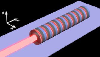
The concept of frozen modes and electromagnetic unidirectionality first emerged within the context of spectral asymmetry of nonreciprocal periodic structures F65 ; D70 ; VEBL97 . In this regard it was recognized that magnetic photonic crystals satisfying certain symmetry conditions VEBL97 ; FV01 can develop a strong spectral asymmetry . An example case of such periodic arrangement is shown in Fig. 1. The basic unit consists of three components: a central magnetic layer “sandwiched” between two misaligned anisotropic layers. The magnetic layer (gray layer in Fig. 1) induces magnetic non-reciprocity which is associated with the breaking of time reversal symmetry due to a static magnetic field or spontaneous magnetization. However, breaking time-reversal symmetry is not sufficient to obtain spectral asymmetry. The symmetry analysis VEBL97 ; FV01 shows that the absence of space inversion is also required. This is achieved with the use of two birefringent layers (blue and red layers in Fig. 1).
The constitutive tensors of the nonmagnetic layers are assumed to be
| (1) |
where describes the magnitude of in-plane anisotropy and the angle defines the orientation of the principle axes in the plane for each of the two nonmagnetic layers. The corresponding constitutive parameters for the magnetic layer are
| (2) |
The gyrotropic parameters are responsible for the magnetic Faraday rotation LL84 . In the simulations below we use the same set of physical parameters as in FV01 . Specifically: , and . The frequency is measured in units of , where is the speed of light in vacuum and is the thickness of the dielectric layers. The width of the ferromagnetic layer is . Without loss of generality we assume that .
The dispersion relation for the infinite periodic stack of Fig. 1 can be calculated numerically using a standard transfer matrix approach FV01 ; RLKKKV12 . We find that displays asymmetry with respect to the Bloch wave vector . For a given structural geometry, the degree of the spectral asymmetry depends on the magnitude of nonreciprocal circular birefringence of the magnetic layer and linear birefringence of the misaligned dielectric layers. If either of the two birefringences is too small, or too large, the spectral asymmetry becomes small. The choice of the numerical parameters allows as to clearly demonstrate the effect of unidirectional lasing using the simplest example of a periodic layered structure shown in Fig. 1. At optical frequencies, very similar results can be achieved by turning the open cavity of Fig. 1 into a ring-like structure note1 .
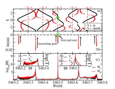
The property of spectral asymmetry has various physical consequences, one of which is the possibility of unidirectional wave propagation FV01 . Let us consider a transverse monochromatic wave propagating along the symmetry direction of the gyrotropic photonic crystal. The Bloch wave vector , as well as the group velocity are parallel to . In Fig. 2a we see that one of the spectral branches develops a stationary inflection point (SIP) for which
| (3) |
An example of a SIP occurring at is marked in Fig. 2a with a circle. At this frequency there are two propagating Bloch waves: one with and the other with . Obviously, only one of the two waves can transfer electromagnetic energy - the one with and corresponding group velocity pointing in the positive direction i.e. . The Bloch eigenmode with has zero group velocity and therefore does not transfer energy. The latter propagating mode is associated with a stationary inflection point Eq. (3) and referred to as the “frozen” mode. Thus a photonic crystal with the dispersion relation similar to that in Fig. 2a displays the property of electromagnetic unidirectionality at . Such a remarkable effect is an extreme manifestation of the spectral asymmetry FV01 .
Next we turn to the analysis of the open photonic structure and the emergence of unidirectional lasing modes. It can be rigorously shown within semiclassical laser theory that the first lasing mode in any cavity is an eigenvector of the electromagnetic scattering matrix ( -matrix) with an infinite eigenvalue; i.e., lasing occurs when a pole of the -matrix is pulled “up” to the real axis by including gain as a negative imaginary part of the refractive index F00 . We therefore proceed to evaluate the scattering matrix associated with the open photonic structure of Fig. 1.
The electric and magnetic fields are designated by the time-harmonic Maxwell equations:
| (4) |
with the solution
| (5) |
where is the frequency. An “external region” encompassing the resonator, extends for . We assume that the permittivity and permeability parameters take constant values where is the identity matrix.
Assuming normal propagation, i.e. , the solutions of Eq. (5) for in the left and right side of the scattering region, are written in terms of the forward and backward traveling waves:
| (6) |
where
| (7) |
The corresponding magnetic field is , where is the unit vector in the -direction.
The relation between the electric field on the left and right sides of the scattering region is described by the 4 transfer matrix :
| (8) |
The transmission and reflection coefficients can be then expressed in terms of the transfer matrix elements as:
| (9) |
From Eqs. (9), we construct the scattering matrix
| (10) |
which, below the laser threshold, connects the outgoing wave amplitudes to their incoming counterparts. For lossless media the permittivity is strictly real . Addition of gain in the system results in a complex permittivity with . Without loss of generality we further assume that the gain is introduced at the dielectric layers with . We have checked that other periodic arrangements of the gain along the cavity give the same qualitative results.
Following Refs. F00 ; LGYCSR11 we analytically continue the scattering matrix to the complex plane. The scattering resonances are then defined by the following (outgoing) boundary conditions, i.e. while , and are associated with the poles of the matrix. It follows from Eqs. (9,10) that the poles of the -matrix can be identified with the complex zeros of the secular equation .
In a passive structure, where is real, the complex poles of the matrix are located in the lower half part of the complex plane due to causality. The real part is associated with the resonant frequencies while the imaginary part describes the fact that the cavity is open LGYCSR11 .
In Fig. 2b we report the motion of the -matrix poles in the complex -plane. Introducing gain to the system leads to an (almost) vertical movement of the poles towards the real axis. This indicates that the lasing frequency of the system is almost equal to the associated mode of the passive structure. At the critical value for which the first one of the poles (marked with a circle in Fig. 2b) crosses the real axis the system reaches the lasing threshold. We have further confirmed the lasing action at by evaluating in Fig. 2c an overall response function, defined as the total intensity of outgoing (reflected or transmitted) waves for either a left or right (single-port) injected wave; that is where and are the respective left and right transmittances and reflectances averaged over polarization. For a lossless passive medium, one always has due to power conservation, whereas indicates that an overall amplification has been realized. Near the lasing frequency takes large values, diverging as the lasing threshold is attained. Furthermore in the insets of Fig. 2c we report the left and right transmittances in the regime of regular FP resonances (left inset) and at a SIP-related frozen mode (right inset). While for FP resonances and exhibit a moderate asymmetry, for a SIP-related mode the asymmetry between them increases dramatically ( by more than two orders of magnitude) indicating strongly asymmetric transport.
A comparison between Fig. 2a and Figs. 2b,c indicates that the lasing threshold frequency is very close to associated with the SIP. While, at this frequency, a right-moving propagating wave (associated to and having large group velocity ) releases most of its energy outside the photonic structure, the mode associated to has extremely small group velocity and allows for a long residence time of the photons inside the structure. The interaction of these photons with the gain medium results in strong amplification which in turn leads to a lasing action. Once the lasing threshold is reached, the outgoing lasing beam is emitted predominantly from the left side of our structure (opposite side from ), therefore producing unidirectional lasing.
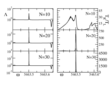
We have confirmed the asymmetry in overall power amplification by analyzing the ratio . The latter is shown in the right column of Fig. 3. Specifically, large values of indicate asymmetric power amplification towards the left while smaller than unity indicates power amplification towards the right. However the actual indication of the non-reciprocal nature of our photonic structure is provided by an analysis of the transmittance asymmetry . This asymmetry exists only in the case that non-reciprocity and gain are simultaneously present.
The magnitude of will be strongly affected by the existence of the SIP. Specifically we expect that the unidirectional amplification near the SIP can be enhanced further by increasing the size of the periodic structure. In this case, the residence time of photons associated with the left moving (slow velocity) mode becomes even longer thus resulting in stronger transmission asymmetries. A scaling analysis of for an increasing number of periods of the grating (see Fig. 3 right panels) indicates that as the system becomes larger the asymmetry becomes increasingly peaked around the unidirectional lasing mode (associated to the SIP), while other picks (associated to standard FP resonances) remain unchanged or even subside. We observe that the unidirectional lasing frequency emerging from of the SIP mode remains fixed and it is insensitive to the size of the periodic structure.
Conclusions - We have introduced a qualitatively new mechanism for unidirectional lasing action which relies on the co-existence of highly non-reciprocal SIP-related frozen modes and gain. The transmittance asymmetry of these modes increases significantly with the size of the structure. As opposed to a conventional lasing cavity utilizing asymmetrically placed reflecting mirrors, a nonreciprocal magneto-photonic structure can produces unidirectionality even at the first (linear) lasing threshold. This unique feature is not available in reciprocal active cavities. Besides, a unidirectional magneto-photonic structure does not need mirrors or any other reflectors in order to trap light and reach the lasing threshold.
The nonreciprocal layered structure in Fig. 1 is just a toy model of a periodic array capable of developing a spectral SIP. It was rather used here in order to demonstrate the proof of principle for the MUL. A future challenging research direction is to propose realistic structures that allow for the co-existence of gain and nonreciprocal SIP. While at infrared and optical wavelengths, the gain is not a problem, the creation of a well-defined nonreciprocal SIP is not a simple matter and is the subject of a whole new area of research. In this respect, a promising way towards building a unidirectional laser could be to add magneto-optical and gain components to a periodic optical waveguide displaying a SIP. Examples of such waveguides can be found, for instance, in gutman , and references therein. This possibility is currently under investigation.
Acknowledgement - This work was sponsored by the Air Force Research Laboratory (AFRL/RYD) through the AMMTIAC contract with Alion Science and Technology, and by the Air Force Office of Scientific Research, LRIR 09RY04COR and FA 9550-10-1-0433. Valuable comments from Dr. T. Nelson are greatly appreciated.
References
- (1) H. Haken, Laser Light Dynamics (NH, Amsterdam, 1986).
- (2) H. E. Türeci, A. D. Stone, L. Ge, S. Rotter, and R. J. Tandy, Nonlinearity 22, C1 (2009).
- (3) K. M. Frahm el al., Europhys. Lett. 49, 48 (2000).
- (4) A. Figotin, I. Vitebskiy, Laser Phot. Rev. 5, 201 (2011)
- (5) R. Fuchs, Philos. Mag. 11, 674 (1965)
- (6) T. O’Dell, The Electrodynamics of Magnetoelectric Media, (North-Holland, Amsterdam, 1970)
- (7) I. Vitebskiy, J. Edelkind, E. Bogachek, U. Landman, Phys. Rev. B 55, 12566 (1997)
- (8) A. Figoton, I. Vitebskiy, Phys. Rev. E 63, 066609 (2001)
- (9) L. D. Landau, E. M. Lifshitz, L. P. Pitaevskii, Electrodynamics of Continous Media, (Pergamon, NY, 1984).
- (10) H. Ramezani, Z. Lin, S. Kalish, T. Kottos, V. Kovanis, and I. Vitebskiy, Optics Express 20, 26200 (2012).
- (11) Due to the inherent weakness of Faraday rotation at optical frequencies, a SIP on the diagram will always be located in close proximity to a photonic band edge. As a consequence, the frozen mode regime in open photonic cavity of Fig. 1 will be overwhelmed with the much more powerful and nearly perfectly symmetric, giant FP resonance FV11 , whose intensity scales as ( is the number of layers). A way to eliminate this and other transmission resonances and preserve the phenomenon of electromagnetic unidirectionality is to use a closed ring-like structure, instead of the open one shown in Fig. 1.
- (12) L. Ge, Y.D. Chong, S. Rotter, H.E. Türeci, A.D. Stone, Phys. Rev. A 84, 023820 (2011).
- (13) T. Baba, Nat. Phot. 2, 465 (2008); N. Gutman, C. Martijn de Sterke, A. A. Sukhorukov, L. C. Botten, Phys. Rev. A 85, 033804 (2012).