The Paradox of Two Charged Capacitors – A New Perspective
Ashok K. Singal
Astronomy and Astrophysics Division
Physical Research Laboratory
Navrangpura, Ahmedabad - 380 009, India.
asingal@prl.res.in
(Submitted 10-07-2015)
Abstract
It is shown that the famous paradox of two charged capacitors is successfully resolved
if all the energy changes in the system are properly considered when some of the charges are
transferred from one capacitor to the other. It happens so even when the connecting wire has
an identically zero resistance, giving rise to no Ohmic losses in the wire.
It is shown that in such a case the “missing energy” goes into the kinetic energy of
conducting charges. It is shown that radiation plays no significant role in resolving
the paradox.
The problem can be formulated and successfully resolved in a novel form,
where the capacitance of the system is increased by stretching the plates of the original capacitor,
without involving any connecting wires in a circuit. There is an outward self-force due to mutual repulsion
among charges stored within each capacitor plate, and the work done by these self-forces during an expansion
is indeed equal to the missing energy of the capacitor system.
1 Introduction
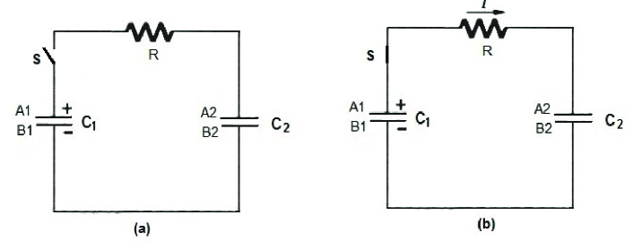
In the famous two-capacitor paradox[1, 2, 3, 4, 5, 6, 7, 8, 9, 10, 11] one of the capacitors, say C1, of capacitance is initially charged to a voltage with charge and energy , while the other similar capacitor, C2, is initially uncharged, thereby the total energy of the system being . Both capacitors are assumed be to identical in every respect. Now C1 is connected to C2 using a conducting wire, resulting in transfer of some charges from C1 to C2. From symmetry each capacitors will end up with charge and voltage , with energy of each as . Therefore the total energy of the system will be . What happened to the other half of the energy?
Puzzling though this might appear at a first look, the loss of energy is easily explained if we consider the Ohmic losses in the connecting wires. Suppose the connecting wires have a resistance (Fig. 1), then the charging current will be and the dissipated energy will be,
| (1) | |||||
The above equation is true for any finite value of . But what happens if there were no Ohmic losses, e.g., if in our ideal hypothetical case the resistance were identically zero (a superconductor!). The total energy in the two capacitors, however, is still half of the initial energy, so where does the remaining energy disappear?
Of course there is nothing special about the two capacitors being identical. In the case the two capacitances and are unequal, the initial stored energy after transfer of charges reduces to . This implies a loss of energy[12]
| (2) |
For equal capacitances () the energy loss reduces to , as derived earlier. Of particular interest is the case for large (), where all stored energy is lost.
Since the charges undergo acceleration while moving from higher to a lower potential in case of zero resistance, can it be that whole of the missing energy appears as radiation from these accelearted charges? The current belief seems to be that the missing energy is radiated away.[13, 14] It should be clarified that here we are not talking of the thermal electromagnetic radiation like in a resistance wire, but of electromagnetic waves radiated from an antenna system. As we will show in Section 4, the present radiation calculations are based on circular arguments. Moreover from maximum possible radiation losses from Larmor’s formula we will argue that missing energy cannot be accounted for by radiation losses, and that the radiation hypothesis does not offer a satisfactory resolution of the paradox.
2 Where does the missing energy go?
The missing energy actually goes into the kinetic energy of conducting charges getting transferred from C1 to C2 for [12]. Actually one has to be cautious when extremely low resistances are considered. The conductivity of a metal is directly proportional to the characteristic time between successive collisions of the charge carriers that results in loss of directional correlation[1, 15]. Drift velocity in the conductor is , where is the electric field and is the electric charge and is the mass of the charge carrier (an electron!). A typical value for in the metals is sec with typical drift velocity usually a fraction of a mm/sec. The resistivity is , and low resistivity implies is large and then the mean free path between collisions () would also be large. In that case there will be fewer collisions and in an extreme case, we could assume that the mean free path will be large enough to be longer than the length of the wire or channel joining the two capacitors. This could be termed as case. Then the conducting charges will steadily gain velocity and kinetic energy as the collisions will be minimal. In that case the charges will not undergo Ohmic losses and when they reach C2 their kinetic energy will be equal to the potential energy difference during the transfer between two capacitors.
The gain in kinetic energy in the absence of Ohmic losses is easily calculated from the change in potential energy of each charge. The charge gains a velocity increment or which implies a kinetic energy gain . For a charge transfer from C1 to C2, the voltage difference between the two becomes . Then the total kinetic energy gained by charges during a total charge transfer from C1 to C2 is,
| (3) |
As the voltage difference between C1 to C2 becomes zero at the end, then , implying that the total kinetic energy gained by the charges from (2) is , in agreement with the energy loss in (2).
When the charges finally get deposited on plates of the capacitor C2 this kinetic energy should get transferred to the plates of C2, which as we discuss later, could even be utilized by an external agency, or else the plates of C2 would get heated. The problem as posed is between two equilibrium states in which the charges are stationary both initially and in the final state. Thus there should be no residual kinetic energy in the system. It implies the charges when finally get deposited on plates of the capacitor C2, they remain stuck there. This means that all the kinetic energy gained by the moving charges in the absence of Ohmic losses, should get transferred to the plates of C2, which we assume to be not free to move (clamped to the lab bench!). There will thus be necessarily inelastic collisions and the plates of C2 would get heated because of these inelastic collisions. There could also be some partial energy loss in sparks but as we show later the whole energy loss cannot be accounted for by the radiation.
Actually is only a mathematical idealization which may not hold good when we go below certain very low resistance values. Let us take a material which can turn into a superconductor, say lead. If we lower its temperature, the resistance of the conductor will reduce steadily up to a certain point (7.22 K for lead),[15] below which it may suddenly become zero as the material turns into a superconductor. That means either it will be a normal electrical resistance with Ohmic losses above this turnover point or it will be zero resistance without Ohmic losses below this point. Thus there is a discontinuity in resistance and one does not have in limit.
Let us examine the idea of in limit in a non–superconductor material. Resistance of a wire is where is the resistivity, is its length and is the cross section. We cannot increase beyond certain values (for example, it cannot be larger than the capacitor plate size), so we can decrease or/and to reduce . Now , the mean free path, meaning . Usually for a few cm long wire, however starting from some finite resistance, as we go to lower , by decreasing and thereby increasing or decreasing , the ratio will decrease. And near some critical value of resistance, say , will approach , that is the mean free path will become equal to the length of the wire or channel joining the two capacitors. At this stage th fraction of the current carrying charges will pass the length of the wire without suffering any collisions and thus without undergoing Ohmic losses. The remaining charges will of course undergo Ohmic losses due to collisions. It is of course statistically a random process. Let us denote the electric current by the latter as and that by the collisionless charges as . Then fraction will be the Ohmic losses and fraction will be the power going into the kinetic energy of charges. Thus there will be sharing of power losses between the two processes, with total power loss as .
Now let us see what will happen as we reduce . Initially with much higher resistance than , with , there will be only , the usual Ohmic losses. As we reach , the Ohmic losses ( fraction) will steadily decrease while the fraction will increase. For much lower resistance than , there will be almost no collisions, there will be only , with the conducting charges gaining the kinetic energy in the absence of collisions and the losses being zero.
In (1) it is implicitly assumed that all charges undergo Ohmic losses however low the collision rates might be (even when ), and accordingly the dissipation losses are calculated. In reality it may not even be proper to still think of resistance below in the usual ohm’s law sense, when the collisions will be few and far between. Therefore might not be very meaningful much below . Thus the mysterious difference between and cases appears only because in the latter it is implicitly assumed that the charges lose their kinetic energy into Ohmic losses however low their collision rates might be, and accordingly we calculate the dissipation losses in (1), while in an identically zero resistance case, Ohmic losses are not even considered.
3 The equivalent case of water transfer between two tanks
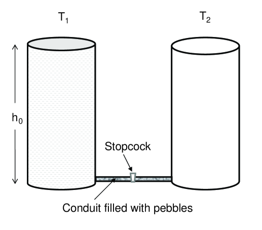
An equivalent example exists in case of a water transfer from one full tank to an identical empty tank under the force of gravity (Fig. 2)[12, 16]. Initially the gravitational potential energy of the water to a height in tank T1 is , where is the density of the water, is the cross-section area of each tank, is the acceleration due to gravity and is the vertical distance. Then is the total quantity (mass) of water and is the gravitational potential. Now we open the stopcock, so that water is transferred from tank T1 into tank T2 through a conduit (Fig. 2). However when we consider the friction with the conduit walls and obstructions within (say, pebbles inside the conduit blocking a free flow of water) then the water loses all its kinetic energy during the transfer to tank T2. At the end with each tank having amount of water up to height , the potential energy of the water in each tank is with the total energy of the system being , exactly as in the two capacitor case. This is because the water in the upper half of tank T1 goes into the lower half of tank T2, then half of the total water mass (i.e., ) which earlier was at a height between and in T1 is now at a height between and in T2, thus ending up at an average height lower by , implying an energy loss of . If there is no friction with the conduit walls (and no obstructions within either), from Bernoulli’s theorem[1] (or from simple energy conversion between potential and kinetic energy) the water would exit with a velocity or , at any moment when the heights of water columns in T1 and T2 are and respectively, with a gravitational potential difference . The water will thus move in the conduit with a kinetic energy that could be even utilized with a suitable device attached to the conduit (a tiny electric power generator!) otherwise this energy will be carried to the tank T2 and ultimately lost as heat there by the time things have settled down.
For unequal tank capacities, let T1 and T2 have cross-section and respectively. Then the total water that will get transfered from T1 to T2 is , and the height of water columns in the two tanks will be . That means this much amount of water would have fallen from a height of initial average value in T1 to a final average value in T2, implying an average height loss of and the loss in potential energy of . It also shows readily why the loss of energy in the tank (charged capacitor) system is the total transferred water (charge) multiplied by half of the initial potential, i.e., .
4 Possibility of radiation losses
In the radiation hypothesis the authors in general assume that the power losses (irrespective of the expression for radiation losses, (see e.g., (8), (9) and (10) in [13]) can be written as and have thus put , where is the potential difference between the two capacitors. Thus their assumption directly leads to and therefore . From our (2) we know the right hand side is irrespective of the time dependence of . No wonder authors also get , as that is a built–in assumption. This way one is bound to get the same final result of energy losses irrespective of any other details of the exact radiation process that might have been assumed (whether it is a magnetic dipole radiation like the authors[13] assumed or some other process), and which could therefore be chosen any arbitrary function of time. In this particular case the authors emphasize that charging/discharging is not instantaneous. But according to this procedure for any arbitrary one could define radiation resistance as , and then writing , one gets which no wonder gives , and actually that way one does not really prove anything about the radiation process. It is not the radiation hypothesis that gets confirmed this way, it is only the a priori assumption of equating radiation losses (or losses in any other way!) to which begets the apparently right answer. For this one does not even need to derive any complicated formulae for radiation expressions and it does not prove in any way that the radiation is that of magnetic dipole or some other “multipole”. Different assumption about the radiation process (whether it is electric dipole or magnetic dipole or some other multipole) only at most may give a different time dependence of function or , but as the time integral of total charge transferred will be and voltage , one is bound to get the result for energy dissipated as . Moreover when charging/discharging is not instantaneous, the Ohmic resistance is not identically zero and the lost energy should then be distributed between dissipation in and radiation. But we find that the energy dissipation is fully satisfied by the Ohmic losses alone (Eq. (1)) even when the resistance reduces in limit to zero () and the radiation hypothesis is not at all needed.
It is possible to estimate how much maximum radiation losses can be there. From Larmor’s formula[17] we know that the energy radiated by a non-relativistic charge accelerated for a time interval (and thus having gained a velocity in the absence of Ohmic losses) is . For all the energy gained by the charge due to the potential difference to go into radiation implies
| (4) |
or
| (5) |
where is the classical electron radius.[17] Thus for all of the missing energy in the capacitor paradox to appear as radiation is possible if and only if the charges move from one capacitor to the other in a time interval of the order in which light travels the classical radius of the electron , which is an impossible condition. In fact the radiation losses, due to the acceleration of the charges will be extremely small and can be made arbitrarily small by making the time over which the charge moves from to large enough. For example, an external agency using some electrical probe (“magic tweezers”),[1] could pick up charges one by one from C1 at a higher potential and deliver them to C2 at a lower potential at a leisurely rate (quasi-statically) and the difference in the potential energy of these charges can be utilized by the transferring agency. There will be no radiation losses, nor will there be any Ohmic loses. We shall further discuss one such alternate example in the next section.
5 A capacitor is charged without using resistive wires
Instead of charging a capacitor C2 from C1 using a wire of zero resistance, we could pose the problem in a different way. Let us suppose that we can expand or stretch the plates of a capacitor quasi-statically so that each plate area becomes double of its previous value, but without changing the plate separation. For simplicity we assume a parallel plate capacitor with dimensions and of the capacitor plates much larger than the plate separation, , so that the electric fields within the capacitor can be considered, with negligible errors, to be uniform as in the case of infinite plates. Let be the initial uniform surface charge density on the two oppositely charged plates, with as the surface area of each plate. Then the electrostatic field is a constant, , in the region between the two plates which thus have a potential difference . The field of course is zero everywhere outside. The mutual force of attraction on each plate is per unit area, and the electric potential energy accumulated in separating the two plates by a distance is . The capacity of a parallel plate capacitor is given by ,[15] and with energy .
With an expansion of the capacitor plates’ areas by a factor of two, the charge density becomes half with the charges now distributed over its double charge capacity. The final energy of the capacitor is now only half of the previous value and the problem returns to the standard two capacitor paradox. The question again rises where has half of the energy gone. Now that there are no connecting wires with their resistance coming into picture, so we do not have to worry about Ohmic losses. There are no radiation losses either. As it is a quasi-static expansion there is no gain in the kinetic energy of current carrier charges. But we still have a problem of the missing energy.
Actually in addition to the force of attraction between two plates of a capacitor, there is also an outward force of repulsion within each capacitor plate. The presence of such self-repulsive forces within the capacitor plates and the work done against them during a Lorentz contraction of the system when the charged capacitor system moves from one inertial frame to another, was first shown explicitly by Singal[18] and accordingly the famous Trouton-Nobel experiment[19] was resolved from energetic points of view.[20] Here we will show by explicit calculations that the energy spent by the capacitor system during expansion is indeed equal to the missing energy, i.e, .
Adapting the calculations of [18] to our present case, we have calculated these force of self-repulsion in Appendix, where we find the expression for the rate of work done during an expansion of capacitor plates by the forces of self-expulsion as (c.f. (LABEL:26)) with as the expansion factor.
Now integrating from initial to a final expansion factor , we get the amount of work done by the system during an expansion as , which is equivalent to the energy loss in (2) with the charge capacitance having increased by a factor . In particular, for , we get the work done during expansion as , which indeed is the energy that were missing in the two equal–capacitor problem.
The above expression for energy change of the capacitor is quite general and it shows that if , whole of the capacitor energy goes into the expansion of the plates (again this amounts to loss of all stored energy in (2) for ). We can look at it in another way. If we were to contract the system (), then we (an external agency!) have to do work against the forces of electrical self-repulsion within the capacitor plates. In fact the energy stored in the capacitor is nothing but the work done in bringing the charged capacitor plates from an infinite size to finite dimensions which is essentially the work done in moving the charges from infinity (against their electrical forces of mutual repulsion) to the finite-sized plates of a capacitor.
6 Conclusion
We have shown that the famous paradox of two charged capacitors is successfully resolved if one properly considers all the energy changes in the system. It was shown that the “missing energy” goes into the kinetic energy of conducting charges when the connecting wire has an identically zero resistance. The problem was formulated in an alternate form, without involving connecting wires in a circuit, where the capacitance of the system is increased by stretching the plates of the original capacitor. The paradox was properly resolved by showing that the work done by the outward self-forces, arising due to mutual repulsion among charges stored within each capacitor plate, during an expansion is equal to the missing energy of the capacitor system. It was also shown that radiation plays no significant role in resolving the paradox.
Acknowledgments
I first learnt of this intriguing paradox from a talk by Prof. S. C. Dutta Roy of IIT Delhi in a conference where he exhorted the audience for a successful solution of this yet unresolved problem of many years, and where he also distributed hard copies of the transparencies of his talk to the interested people.
7 Appendix
7.1 Work done during a stretching of the plates of an ideal capacitor

By an ideal capacitor we mean here that the surface charge density is uniform throughout on both plates. We assume that the charges somehow remain ”glued” on the surface and the surface charge density decreases as the rubber–like plate surfaces are stretched. Let us assume the plates to be lying in the - plane (Fig. 3). The electric field between the plates is parallel to the -direction. The potential energy of the system as well as the energy in the electrostatic field is , where are the plate dimensions and is the plate separation.
Let us assume that we expand the plate dimensions by say, stretching them along the -axis. It should be noted that there are electromagnetic forces of repulsion on charges within each plate, along its surface. We may generally ignore these repulsive forces, but during a stretching of the plates parallel to the plate surface, work will be done by these forces. The forces are indeed small near the plate-centers and become appreciable as we go away from the plate centers, becoming maximum near the plate-edges, and it might seem that for and large enough as compared to , the effect of these forces should be negligible. But as we will see below, the amount of work done by theses forces during a plate expansion is proportional to the plate dimensions.
As the expansion considered is along the -axis alone, then only the -component of the forces of repulsion will be relevant for our purpose. Now the mutual electrostatic force of repulsion between two line charges, each with a linear charge density and of a length , separated by a distance is easily calculated to be .

References
- [1] D. Halliday, R. Resnick and J. Walker, Fundamentals of Physics, 5th ed. John Wiley, New Jersey 1997, Ch. 15, 26, 27
- [2] R. A. Powel, Am. J. Phys. 47, (1979) 460-462
- [3] K. Mita and M. Boufaida, Am. J. Phys. 67, (1999) 737-739
- [4] C. Zucker, Am. J. Phys. 23 (1955) 469-469
- [5] R.P. Mayer, J.R. Jeffries and G.F. Paulik, IEEE Trans. Education 36 (1993) 307-309
- [6] K. Lee, Eur. J. Phys. 30 (2009) 69-74
- [7] C. E. Mungan, Eur. J. Phys. 30 (2009) L59-L63
- [8] A. M. Abu-Labdeh and S. M. Al-Jaber, J. Electrostatics 66 (2008) 190-192
- [9] W. J. O’Connor, Phys. Educ. 32 (1997) 88
- [10] S. Mould, Phys. Educ. 33 (1998) 323
- [11] A. M. Sommariva, IEE Proceedings - Circuits, Devices and Systems 150, issue 3 (2003) 227-231
- [12] D. P. Korfiatis, WSEAS Trans. Circuits and Systems 6 (2007) 76-79
- [13] T. B. Boykin, D. Hite and N. Singh, Am. J. Phys. 70 (2002) 415-420
- [14] T. C. Choy, Am. J. Phys. 72 (2004) 662-670
- [15] E. M. Purcell, Electricity and Magnetism, 2nd ed., McGraw-Hill, New York 1985, Ch. 3, 4, Appendix C
- [16] S. Krishnan and M. Rao, Am. J. Phys. 50 (1982), 662
- [17] J. D. Jackson, Classical Electrodynamics, 2nd ed., John Wiley, New York 1975, Ch. 14
- [18] A. K. Singal, J. Phys. A 25 (1992), 1605–1620
- [19] F. T. Trouton and H. R. Noble, Phil. Trans. Roy. Soc. London A 202 (1903), 165-181
- [20] A. K. Singal, Am. J. Phys. 61 (1993), 428-433