Robust frequency stabilization of multiple spectroscopy lasers with large and tunable offset frequencies
Abstract
We demonstrate a compact and robust device for simultaneous absolute frequency stabilization of three diode lasers whose carrier frequencies can be chosen freely relative to the reference. A rigid ULE multi-cavity block is employed, and, for each laser, the sideband locking technique is applied. Useful features of the system are a small lock error, computer control of frequency offset, wide range of frequency offset, simple construction, and robust operation. One concrete application is as a stabilization unit for the cooling and trapping lasers of a neutral-atom lattice clock. The device significantly supports and improves the operation of the clock. The laser with the most stringent requirements imposed by this application is stabilized to a linewidth of 70 Hz, and a residual frequency drift less than 0.5 Hz/s. The carrier optical frequency can be tuned over 350 MHz while in lock.
In precision spectroscopic experiments with cold atoms and molecules the need arises to stabilize the frequency of lasers to such a level that both the residual absolute frequency error and the residual linewidth of the laser radiation are well below the linewidth of the transition of the species under study. For example, in the application of the strontium optical lattice clock, one cooling laser should have its absolute frequency stabilized and its linewidth reduced to a level of 1 kHz [1].
Often, a frequency reference capable of providing adequate frequency control is not available at the required optical frequency for the spectroscopic application. For example, the frequency reference may be a rigid and therefore non-tunable ULE cavity, or a ro-vibrational transition of a molecular gas in a cell. The spacing between neighboring frequency markers (TEM00 modes or molecular transitions), , will typically be on the order of 1 to a few GHz, and therefore the offset between the goal frequency and the reference frequency may have to be as large as GHz. Such a gap can in principle be bridged with one or more acousto-optic modulators. Another approach is the serrodyne technique recently reported [Houtz2010], in which a single sideband is produced by means of waveguide electro-optic phase modulator (EOPM).
Here, we utilize the sideband locking technique [2]. It is based on the use of a EOPM, driven by a simple, easily available electrical waveform, a phase-modulated (PM) harmonic signal (Alternatively, an amplitude-modulated harmonic signal could be used). This approach has the advantage of being fiber-based and compact, and of allowing bridging gaps of many GHz, limited only by the EOPM bandwidth. It also provides an unambiguous lock state, and introduces (for most purposes) a negligible lock frequency offset error. Moreover, it was previously shown that the lock instability may reach a level comparable to that of a standard lock using the carrier only [2].
We apply this technique for the stabilization of three diode lasers (689 nm, 813 nm, 922 nm) to a compact reference cavity unit. This laser set is required for cooling and trapping strontium atoms in an optical lattice, and we thus realize a frequency stabilization system (FSS) which thanks to its compactness may serve as a prototype for transportable or space optical clocks [3].
A schematic of the FSS is shown in Fig. 1.
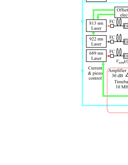
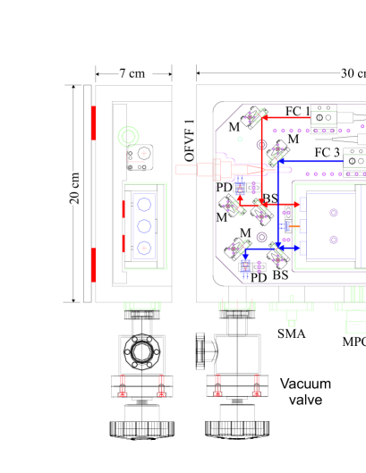
The reference for the stabilization is a single, temperature-stabilized ULE block containing three non-tunable cavities. The block is mounted in a 30 cm 20 cm 10 cm UHV chamber which is also temperature-stabilized. No special effort has been undertaken to minimize vibration sensitivity, in order to keep the unit simple and compact. Cavity 3 (fused silica substrates, finesse 1500) stabilizes the 813 nm and 922 nm lasers. Cavity 2 is used for the most demanding stabilization (689 nm laser), has ULE mirror substrates and a finesse . The first cavity is suitable for stabilization of repumper lasers (679 nm and 707 nm) but this is not currently implemented, since their passive stability is sufficient. The mirror curvature radii are 0.5 m, and the substrates are AR-coated. Each laser wave passes through its respective EOPM, and up to two laser waves are combined by a fiber splitter and coupled to two fundamental modes of a single cavity. Single-mode fibers with vacuum feed-through deliver the laser light into the chamber. Fig. 2 shows technical details of the optics subsystem.
We briefly summarize salient features of the sideband locking technique. A (typically large) modulation frequency bridges the gap between the target frequency and the reference frequency . In addition, a smaller modulation frequency serves to produce sidebands for Pound-Drever-Hall (PDH) locking. The drive voltage supplied to the EOPM is therefore chosen to be a PM electric signal, . The electric field of the laser wave exiting the EOPM is then a “cascaded” PM optical wave . An expansion of this expression shows that the amplitude of the component offset from the carrier by , , is given by sgnsgn. Here sgn and are the sign and Bessel function, respectively.
Consider the () triplet of sidebands. The two components have opposite signs. Therefore, when the central component interrogates a reference line, a PDH error signal can be obtained by demodulation of the photodetector signal at the frequency . The slope of the error signal for the triplet (upper 1st-order sideband triplet) is opposite to that of the triplet (lower 1st-order sideband triplet), since the amplitudes of the sidebands differ by the factor . Note that there are no PDH sidebands associated with the carrier (for the amplitudes are zero for any ). If desired, one can make use of the 2nd-order sidebands in order to bridge larger gaps , which enhances the usefulness of the method. A sufficiently strong modulation index is then required. In our system, we use only the 1st-order sidebands. The slope of the error signal is proportional to . The modulation index of the electrical signal can be optimized so as to maximize to 0.34 for .
The reference cavities have 1.48 GHz free spectral range.
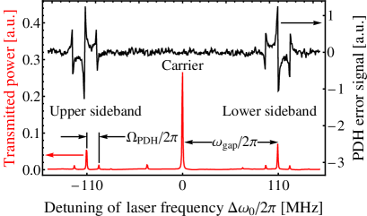
RF signals with frequencies up to nearly this value can be generated with a low-cost DDS. Our home-built DDS is based on a 400 MHz AD9910 chip (Analog Devices). It provides the required PM signal, whose properties can be keyed in via front panel or submitted via USB interface. Frequencies up to 400 MHz are produced directly, while frequencies between 400 and 700 MHz are produced by a AMK-2-13 frequency doubler (Minicircuits) which is switched on or off by a Mega64L micro-controller (Atmel). The DDS also provides a separate output to the PDH electronics. Finally, the DDS has an external 10 MHz reference input allowing for highest accuracy and stability. The DDS signal is amplified by a first amplifier (GALI-24, Mini-Circuits) and further amplified to approximately 1 W by an external power amplifier (CGD1046HI, NXP). If gaps 700 MHz are to be bridged, one can resort to a commercial microwave synthesizer with PM option.The waveguide EOPM (Jenoptik) is fiber-coupled and has an electrical bandwidth of 2 GHz. The laser radiation at the output of the EOPM is coupled into the reference cavity, and the wave reflected from the cavity is detected as usual for the PDH technique. The total optical power exiting the collimator is approximately W. The photodetector output is demodulated with the reference signal from the DDS, and the error signal is generated. Fig. 3 shows the spectrum of the modulated input light and the error signal.
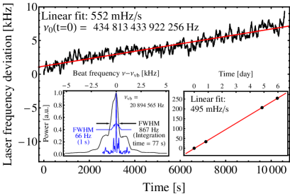
The error signal is amplified and filtered by a PID servo that controls both the diode laser current and the grating position. The choice of the sign of the servo gain determines whether the upper () or lower () 1st-order sideband is locked to the cavity resonance.The lasers can be robustly stabilized and remain in lock for extended periods. The performance of the 689 nm laser was characterized in detail using the virtual beat technique [4, 5]. By simultaneous provision of a beat of the stabilized laser with a Ti:Sapphire frequency comb and of an ultra-stable reference laser (1 Hz linewidth) with the comb, and combination of the two beat notes and the comb offset frequency into a virtual beat linewidth, the linewidth can be determined. Additionally, the absolute frequency of the laser and its drift are determined by optical frequency measurement, with the comb stabilized to a hydrogen maser. Fig. 4 shows the results. A linewidth of approximately 70 Hz on the 1 s time scale, increasing to 0.9 kHz on the minute-timescale, and a linear drift of 0.5 Hz/s were achieved. The 922 nm and 813 nm lasers were characterized by observing the beat of each laser with the comb. The results show a linewidth less than 1 MHz and a linear drift of 4 Hz/s.
As one aspect of the robustness, the systematic dependence of the laser frequency on the EOPM drive power has been measured. The sensitivity is -1.1 kHz/dBm referred to the DDS source output. Taking into account the measured instability of the amplified EOPM drive signal (approx. 2% on the time scale of hours), we estimate that the corresponding frequency uncertainty (relative to the cavity resonance) is of the order of 100 Hz. It is likely due to residual amplitude modulation (RAM), since for simplicity and compactness, no countermeasures, such as polarization optics , were taken. This uncertainty is sufficiently low for a 2 stage cooling laser of a lattice clock and also for many other applications.
Another test of the robustness of the FSS consisted in it and observing the shift of the 689 nm laser locked to it, see Fig. 5.
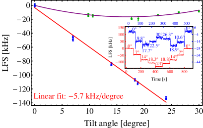
The frequency shift when the cavity is tilted along its axis is linear in the tilt angle with sensitivity kHz/degree. For tilt around an axis in the optical plane and orthogonal to the cavity axis, the sensitivity is less than 2 kHz/degree. Considering the tightest specification for absolute frequency instability, 1 kHz over 1 hour for the 689 nm laser, an angle stability of 0.1 degree is required for the device. This is feasible in a stationary application.
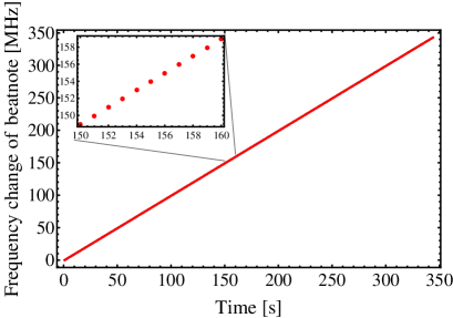
Thanks to the sideband locking technique, an important feature of the FSS is the freedom to change the carrier frequency while the laser remains in lock, by changing the gap frequency . This is achieved in a robust way by ramping the DDS output frequency via computer control. The tuning range for is limited to , because the opposite 1st-order triplet will eventually move over the adjacent resonance and contribute to the error signal, disturbing the lock. In practice, we have swept between 50 MHz and 400 MHz and thus by 350 MHz, see Fig. 6. A tuning speed of 1 MHz/s is compatible with maintaining lock. The characterization of the sweep was done by recording the beat between the laser locked to the FSS and an independent 689 nm laser referenced to the Sr atomic absorption line.
Since the modulation index of the EOPM depends on the frequency of the applied modulation , the amplitude of sideband triplet varies with even for constant . Therefore, during the frequency sweep, the gain of the laser current feedback was reduced in order to prevent the lock from oscillating. This adjustment was done manually but could in principle be implemented in the computer control.
The ability to change the gap frequency is very useful, e.g., for making well-defined frequency scans of the carrier frequency across a narrow spectral feature. Another use is the compensation of the frequency drift of the reference cavity: the laser frequency drifts can be corrected by modifying periodically their so as to optimize the signals produced in the excitation of the cold atoms. If the drift of the reference is known or periodically measured, this information can be used to digitally change the gap frequency, such that the carrier frequency remains stable in time. The FSS is prepared to implement such a correction using an additional, ultra-stable laser as an absolute reference, which probes the frequency drift of the ULE block, see dashed blue subunit in Fig. 1. In an atomic clock application, such a laser is naturally available: the clock laser. Its long-term frequency stability is equal to the atomic clock stability, since it is steered to the atomic resonance. In our proposed cavity drift correction concept, the clock laser wave is coupled into its EOPM and then into cavity 2. The offset frequency for the clock laser is set to the resonance of the cavity and an error signal is generated as for the other lasers. A software analyzes the error signal and drives it to zero by controlling . The variations of with time are monitored and used to correct digitally the values of of the other locked lasers.
The FSS was shipped from Düsseldorf to Firenze and integrated into a 88Sr clock apparatus [3]. The 689 nm laser was stabilized with a home-built PID servo, while the 813 nm and 922 nm lasers were stabilized using the DIGILOCK 110 (TOPTICA). After locking the laser, the offset frequencies of the two cooling lasers were tuned so as to optimize the number of trapped atoms. Approximately, atoms were loaded into the optical lattice via a 1st stage and a 2nd stage MOT. The atom permanence half-life in the lattice was s. Magnetically induced spectroscopy of the clock transition was performed and a linewidth of 100 Hz was observed.
In summary, we have demonstrated a compact and transportable frequency stabilization (FSS) system for multiple lasers, in this concrete case for a Sr lattice optical clock. The FSS uses the resonances of two medium-finesse ULE cavities inside a single block as frequency references to stabilize three lasers at 689 nm, 813 nm, and 922 nm. For the laser with the most stringent requirements a linewidth of 70 Hz and a residual frequency drift less than 0.5 Hz/s is achieved, a very good result considering that no efforts have been made to isolate the system from external vibrations. Additionally, the system is robust as evidenced by tilting the cavity without loss of lock and with only moderate frequency change.As proof of functionality of the FSS, the system was integrated into a transportable Sr atomic clock apparatus. The initial tests show that, thanks to the FSS, a more stable population of atoms in the blue MOT, the red MOT, and the lattice are achieved, as compared to stabilization to an atomic beam spectroscopy signal, improving the operation of the clock apparatus as a whole. The easy tunability of the laser frequencies helps to find the best frequencies for maximum number of atoms stored in the lattice. Besides this particular application, we believe that similar systems can be used for a variety of experiments employing cold atoms and molecules.
Acknowledgments. We are grateful to D. Iwaschko, P. Dutkiewicz and U. Sterr (PTB) for support. The research leading to these results has received funding from the European Union Seventh Framework Programme (FP7/2007-2013 grant agreement 263500).
References
- [1] N. Poli, G. Ferrari, M. Prevedelli, F. Sorrentino, R.E. Drullinger, and G.M. Tino, Spectrochim. Acta A-M. 63, 981 (2006).
- [2] J. I. Thorpe, K. Numata, J. Livas, Opt. Expr. 16 15980 (2008).
- [3] S. Schiller, A. Görlitz, A. Nevsky, S. Alighanbari, S. Vasilyev, C. Abou-Jaoudeh, G. Mura, T. Franzen, U. Sterr, S. Falke, Ch. Lisdat, E. Rasel, A. Kulosa, S. Bize, J. Lodewyck, G. M. Tino, N. Poli, M. Schioppo, K. Bongs, Y. Singh, P. Gill, G. Barwood, Y. Ovchinnikov, J. Stuhler, W. Kaenders, C. Braxmaier, R. Holzwarth, A. Donati, S. Lecomte, D. Calonico, F. Levi, arXiv:1206.3765 [quant-ph].
- [4] H. R. Telle, B. Lipphardt, and J. Stenger, Appl. Phys. B 74, 1 (2002).
- [5] S. Vogt, C. Lisdat, T. Legero, U. Sterr, I. Ernsting, A. Nevsky, and S. Schiller, Appl. Phys. B 104, 741 (2011).