An accordion lattice based on the Talbot effect
Abstract
We introduce an idea of producing an optical lattice relied on the Talbot effect. Our alternative scheme is based on the interference of light behind a diffraction grating in the near-field regime. We demonstrate 1-D and 2-D optical lattices with the simulations and experiments. This Talbot optical lattice can be broadly used from quantum simulations to quantum information. The Talbot effect is usually used in lensless optical systems, therefore it provides small aberrations.
keywords:
Talbot effect; Optical diffraction; Diffraction gratings1 Introduction
Optical lattices are of great importance in fields of quantum many body systems and even in quantum applications such as quantum information technology [1, 2, 3]. An experiment of ultracold quantum gases in optical lattices is attractive for quantum investigations in fundamental physics since it provides a light-matter interaction in optical dipole forces [4] which can be both of low-field and high-field seeking states [5]. The interaction of bosonic atoms on the lattices, Bose-Hubbard model, can be realized in optical lattices [6]. Storing atoms in optical lattices can be used as a quantum register in a Mott insulator phase [7] which was suggested as a quantum computer [8, 9, 10, 11]. Loading ultracold atoms of Bose-Einstein condensate (BEC) [12, 13] in an optical lattice was studied [14]. A study of ultracold atoms in an optical lattice with dynamically variable periodicity allows us to perform versatile experiments from quantum simulations with a small lattice spacing to quantum information with a large lattice spacing [15, 16]. Therefore, an optical lattice with real-time variable lattice spacings (accordion lattice) is worth for studying. Among various schemes to produce accordion lattices, the use of two parallel beams encountered each other at the focal plane of a lens is an excellent one [17, 18].
Here, we introduce an idea of producing an alternative optical lattice relied on the Talbot effect [19, 20, 21, 22]. There were some early proposed ideas and experiments of optical lattice produced by the Talbot effect but with a binary shape of the opening fraction (the ratio between the slit width and the grating period) [23, 24, 25]. We here study the Talbot optical lattice with various opening fractions and grating periods. We demonstrate our idea with the simulations and experiments. Talbot optical lattice is simple, and more stable. Also, the main setup is usually used in lensless optical systems, therefore it provides small aberrations.
2 Theory and method
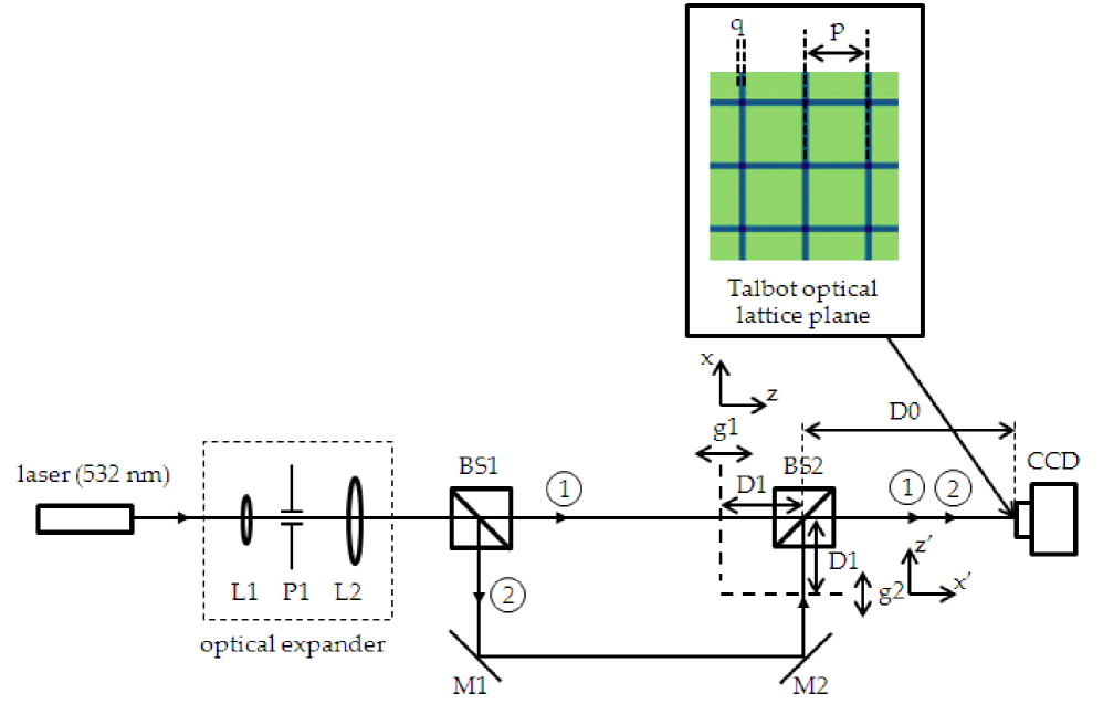
We show briefly the construction of optical lattice by using near-field diffraction pattern in the Talbot effect. Assuming a plane wave with the wave number propagating along -axis falls onto a diffraction grating at (Fig. 1). If the grating has the periodic modulation in the direction, the wave function propagates for a distance behind the grating can be expressed as [22]
| (1) |
where , , and is the Talbot length. Here, is the grating period, the coefficient represents the Fourier decomposition component of the periodic for the grating with an opening fraction . The corresponding intensity gives the near field interference pattern, so-called optical carpet [22]. This carpet can be considered as a 1-D optical lattice (Fig. 2(a) inset). Similarly, one can obtain the wave function also propagates along -axis through the second grating (g2) but has diffraction pattern along -axis by replacing in Eq. (1) by , i.e. (Fig. 1). Therefore, we can produce a 2-D optical lattice that can be formed by the superposition of these two mentioned wave functions (Fig. 1). The intensity pattern produced by these combined waves can be obtained,
| (2) |
3 Experiment
Our 1-D Talbot optical lattice is produced with the 5 mW green diode laser () as a coherent source which is expanded by an optical telescope to a diameter of 20 mm, and then illuminated a diffraction grating and downstream monitored by the imaging detection, i.e. CCD camera (DCU223C, Thorlabs). The telescope is used to expand the laser beam in order to make the homogeneous light amplitude distribution for the whole grating [26] which makes the highest contrast of the Talbot image. The diffraction grating (chromium on glass, Edmund Optics inc., ) can be rotated with the rotation grating holder (LCRM2/M, Thorlabs) in order to align it to the camera axis. The distance from the first grating (g1) to the CCD (D0+D1) is set to be one Talbot length (75.2mm). Therefore, the lattice spacing (p) is equal to the grating period and the width (q) is half of the grating period for our demonstrated setup. The lattice depth can be estimated by measuring the intensity behind the grating with the photodiode (PM120D, Thorlabs).
The setup can be simply expanded to 2-D lattice by adding an additional grating (g2) as shown in Fig. 1. This second grating, which is similar to the first one, is placed and aligned perpendicular to the first grating (g1) where the grating lines of the first grating and second grating are perpendicular to each other or parallel to the -axis and -axis, respectively (Fig. 1). Then, the Talbot patterns are combined via the beamsplitter (BS2) and formed the 2-D optical lattice on the CCD plane (shown in the inset of Fig. 1). Each grating is placed above the translation stage (MTS50/M-Z8E, resolution 1.6 m, Thorlabs) in order to adjust the length between the grating and the CCD (D0+D1). For the 2-D optical lattice, the setup can possibly be set with a 2-D cross grating but in this work we want to be able to demonstrate for both of 1-D and 2-D lattices.
4 Results and discussion
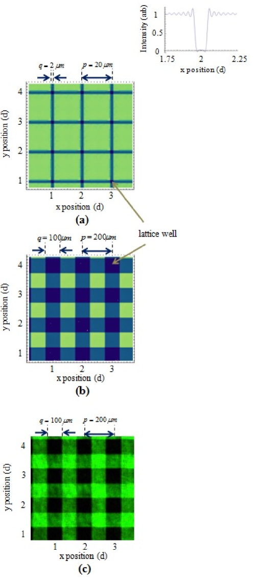
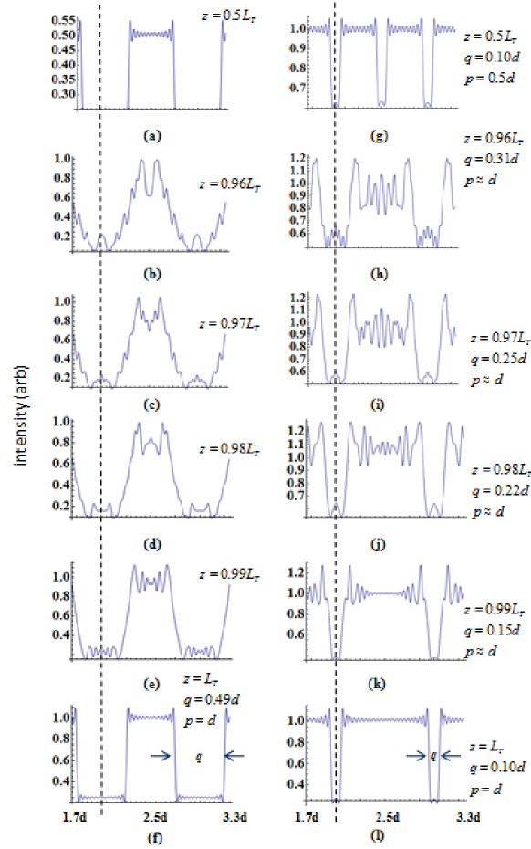
We started with the simulations of the Talbot optical lattice. The 2-D optical lattices, simulated using Eq. (2) are shown in Fig. 2 (a) and (b). They were calculated with the truncated sum at . The grating periods and opening fractions of and , the laser wavelength of 532 nm, and the longitudinal distance were used in the calculations. The optical lattice shown in Fig. 2 (a) has the square shape of 2m width (q) with the lattice spacing (p) of 20m which are corresponded to the grating periods m and opening fractions of the grating itself. The inset of Fig. 2 (a) represents a 1-D optical lattice with the same conditions but using only the first grating g1. The lattice depth can be varied with the laser intensity and subsequently calculated to the potential depth. Also, Fig. 2 (b) is the square optical lattice with the lattice spacing of 200m and width of about 100m since the gratings have . We proved our idea by the experiment as shown in Fig. 1 and the result shown in Fig. 2 (c). Fig. 2 (b) and (c) are the calculation and experiment with the same conditions. They show the similar shapes of the optical lattice. Fig. 3 shows the cross section of 2-D optical lattices. The continuous change of the lattice spacings and lattice widths can be done by changing the longitudinal distances and for both gratings according to the fractional Talbot effect [22]. The and distances were varied equally from to () (Fig. 3 (g)-(l)). The changes of and from to are corresponded to the lattice width of m to m (Fig. 3 (h)-(l)). The width can also be m at (not shown in the figure). Therefore, the width can be varied from m to m with the small distance of about 75m ( to ). The lattice spacing is also changed to half of the grating period at . In contrast to this result, the condition of gives almost unchanged lattice width and spacing when and varied equally from to (Fig. 3 (a)-(f)). These results show that the real-time control of the lattice width and spacing can be done with an asymmetrical grating, that is to say, . In addition, the center of the lattice is stable and has no significant translation from the center within this small distance.
5 Conclusions
In conclusions, a 1-D and 2-D optical lattices with real-time control of the lattice spacing and width have been studied in our simulations and experiments. The optical lattice is produced by the Talbot effect. The lattice spacing and width can be changed with the longitudinal distances ( and ) due to the Talbot and fractional Talbot effect. The results show that a symmetrical grating such as the opening fraction of 0.5 is not possible for changing the lattice spacing and width within a short distance, whereas an asymmetrical grating () provides the control change of m to m with the small longitudinal distance of about 75m. An optical lattice produced by the Talbot effect overcomes the two counter-propagating laser beams, i.e. the standing wave of light because the variation of the lattice spacing and width can be more flexible than . Since the lattice spacing and width of the Talbot optical lattice can be modified with the longitudinal distance which also respected to the grating period, one can obtain almost arbitrary lattice spacings and widths with this method. The system can easily be extended to 3-D lattice by addressing atoms in a different layer of various longitudinal distances inside the Talbot optical lattice. Atoms and molecules in periodic potentials are an excellent tool for studying quantum mechanics. Even hot molecules can be used in an experiment of light-matter interaction with periodic potential [27]. The Talbot optical lattice can be ultimately employed to study quantum tunneling when the spacing is small and possible quantum register for the large spacing.
S.D. acknowledges the support grant from the office of the higher education commission, the Thailand research fund (TRF), and Faculty of Science, Burapha university under contract number MRG5380264 and the National Electronics and Computer Technology Center, National Science and Technology Development Agency and Industry/University Cooperative Research Center (I/UCRC) in HDD Component, the Faculty of Engineering, Khon Kaen University. We thank Nupan Kheaomaingam for useful discussions.
References
- [1] Bloch I. Ultracold quantum gases in optical lattices. Nature Physics 2005;1:23-30.
- [2] Jaksch D. Optical lattices, ultracold atoms and quantum information processing. Contemporary Physics 2004;45:367-81.
- [3] Monroe C. Quantum information processing with atoms and photons. Nature 2002;416:238-46.
- [4] Bernet S, Abfalterer R, Keller C, Oberthaler MK, Schmiedmayer J, Zeilinger A. Matter waves in time-modulated complex light potentials. Phys. Rev. A 2000;62:023606.
- [5] Bloch I. Quantum gases in optical lattices. Phys. World 2004;17:25-9.
- [6] Lewenstein M, Sanpera A, Ahufinger V, Damski B, Sen(De) A, Sen U. Ultracold atomic gases in optical lattices: mimicking condensed matter physics and beyond. Advances in Physics 2007;56:243-379.
- [7] Greiner M, Mandel O, Esslinger T, Haensch TW, Bloch I. Quantum phase transition from a superfluid to a Mott insulator in a gas of ultracold atoms. Nature 2002;415:39-44.
- [8] Feynman RP. Quantum mechanical computers. Found. Phys. 1986;16:507-31.
- [9] Porto JV, Rolston S, Tolra BL, Williams CJ, Phillips WD. Quantum information with neutral atoms as qubits. Phil. Trans R. Soc. Lond. A 2003;361:1417-27.
- [10] Jaksch D, Cirac JI, Zoller P, Rolston SL, C t R, Lukin MD. Fast Quantum Gates for Neutral Atoms. Phys. Rev. Lett. 2000;85:2208 11.
- [11] Prevedel R, Stefanov A, Walther P, Zeilinger A. Experimental realization of a quantum game on a one-way quantum computer. New J. Phys. 2007;9:205.
- [12] Davis KB, Mewes M-O, Andrews MR, van Druten NJ, Durfee DS, Kurn DM, Ketterle W. Bose-Einstein Condensation in a Gas of Sodium Atoms. Phys. Rev. Lett. 1995;75:3969 73.
- [13] Anderson MH, Ensher JR, Matthews MR, Wieman CE, Cornell EA. Observation of Bose-Einstein Condensation in a Dilute Atomic Vapor. Science 1995;269:198-201.
- [14] Denschlag JH, Simsarian JE, Haeffner H, McKenzie C, Browaeys A, Cho D, Helmerson K, Rolston SL, Phillips WD. A Bose-Einstein condensate in an optical lattice. J. Phys. B: At. Mol. Opt. Phys. 2002;35:3095-114.
- [15] Al-Assam S, Williams RA, Foot CJ. Ultracold atoms in an optical lattice with dynamically variable periodicity. Phys. Rev. A 2010;82:021604(R).
- [16] Fallani L, Fort C, Lye J, Inguscio M. Bose-Einstein condensate in an optical lattice with tunable spacing: transport and static properties. Optics Express 2005;13:4303-13.
- [17] Li TC, Kelkar H, Medellin D, Raizen MG. Real-time control of the periodicity of a standing wave: an optical accordion. Optics Express 2008;16:5465-70.
- [18] Williams RA, Pillet JD, Al-Assam S, Fletcher B, Shotter M, Foot CJ. Dynamic optical lattices: two-dimensional rotating and accordion lattices for ultracold atoms. Optics Express 2008;16:16977-83.
- [19] Talbot HF. Facts relating to optical science. Philosophical Magazine series 1836;9:401-7.
- [20] Lohmann AW, Silva DE. An interferometer based on the Talbot effect. Optics Communications 1971;2:413-5.
- [21] Berry M, Marzoli I, Schleich W. Quantum carpets, carpets of light. Physics World 2001;14;1-6.
- [22] Case WB, Tomand M, Deachapunya S, Arndt M. Realization of Optical Carpets in the Talbot and Talbot-Lau Configurations. Optics Express 2009;17;20966-74.
- [23] Ovchinnikov YB. Coherent manipulation of atoms by copropagating laser beams. Phys. Rev. A 2006;73: 033404.
- [24] Sun YY, Bu J, Ong LS, Yuan X.-C. Simultaneous optical trapping of microparticles in multiple planes by a modified self-imaging effect on a chip. Appl. Phys. Lett. 2007;91:051101 - 051101-3.
- [25] Sun YY, Yuan X-C, Ong LS, Bu J, Zhu SW, Liu R. Large-scale optical traps on a chip for optical sorting. Appl. Phys. Lett. 2007;90:031107 - 031107-3.
- [26] Salama NH, Patrignani D, De Pasquale L, Sicre EE. Wavefront sensor using the Talbot effect, Optics & Laser Technology 1999;31:269-72.
- [27] Gerlich S, Hackermueller L, Hornberger K, Stibor A, Ulbricht H, Gring M, Goldfarb F, Savas T, Mueri M, Mayor M, Arndt M. A Kapitza-Dirac-Talbot-Lau interferometer for highly polarizable molecules. Nat. Phys. 2007;3:711-15.