Roton excitations in a trapped dipolar Bose-Einstein condensate
Abstract
We consider the quasiparticle excitations of a trapped dipolar Bose-Einstein condensate. By mapping these excitations onto linear and angular momentum we show that the roton modes are clearly revealed as discrete fingers in parameter space, whereas the other modes form a smooth surface. We examine the properties of the roton modes and characterize how they change with the dipole interaction strength. We demonstrate how the application of a perturbing potential can be used to engineer angular rotons, i.e. allowing us to controllably select modes of non-zero projection of angular momentum to become the lowest energy rotons.
pacs:
67.85-d, 67.85.BcI Introduction
Bose-Einstein condensates (BECs) with dipole-dipole interactions (DDIs) have been realized with highly magnetic atoms Griesmaier et al. (2005); *Pasquiou2011a; Lu et al. (2011); *Lu2012a; Aikawa et al. (2012). This interaction is both long ranged and anisotropic and is predicted to open up an array of new phenomena for exploration using ultra-cold atomic gases Baranov (2008); Lahaye et al. (2009). An important prediction is that a rotonlike excitation will emerge in a dipolar BEC which is tightly confined along the direction that the dipoles are polarized Santos et al. (2003). There has been significant theoretical interest in schemes for detecting rotons Corson et al. (2013a, b); Jona-Lasinio et al. (2013a); Blakie et al. (2012); Bisset and Blakie (2013) and on the role of rotons in the behavior of dipolar BECs, such as response to perturbations Wilson et al. (2008), the critical velocity for the breakdown of superfluidity Wilson et al. (2010); Ticknor et al. (2011), pattern formation Nath and Santos (2010); Wilson et al. (2012), and density fluctuations Bisset and Blakie (2013); Blakie et al. (2013); Klawunn et al. (2011).
Initial theoretical predictions of Santos et al. Santos et al. (2003) were made for a BEC of dipoles polarized and confined in the direction (i.e. untrapped in the -plane). In this case the quasiparticles are planewaves and the rotons occur as a local minimum in the dispersion relation at wavevector , where is the confinement length 111We also note that in tight two-dimensional geometry, where the DDI is purely repulsive, rotons can emerge under conditions of strong interactions or high density, however these occur at a wavevector set by the inverse particle spacing, e.g. see Filinov et al. (2010); Hufnagl et al. (2011).. While robust numerical techniques for calculating the quasiparticles of a fully trapped dipolar BEC have been developed (e.g. see Ronen et al. (2006)), there has been no comprehensive study of rotons for the trapped system. However, some aspects of the lowest energy rotons in the trapped system have emerged in studies of condensate structure and stability Ronen et al. (2007); Asad-uz Zaman and Blume (2009, 2010, 2011); Martin and Blakie (2012); Ticknor (2012a). Recent work Jona-Lasinio et al. (2013b) presented an approximate description of the trapped rotons by re-quantizing a local density treatment of the excitation spectrum, enabling an analytic prediction for the roton spectrum and wavefunctions.
In this paper we directly examine the structure and properties of the roton modes that emerge in a pancake shaped, trapped dipolar BEC using full three-dimensional numerical calculations. We produce a dispersion relation-like characterization for the quasiparticle excitations by mapping these excitations onto linear and angular momentum, and use this to identify the rotons. Strikingly, in the trapped system the rotons emerge as fingers in the dispersion relation-like characterization (see Fig. 1). We then examine the properties of the rotons in each finger, as well as considering how the fingers change with the DDI strength. Finally we show that by perturbing the harmonic trap with a repulsive Gaussian potential the character of the roton fingers can be modified. Notably, we observe that modes with higher values of angular momentum projection become the minimum energy rotons in each finger, thus allowing a controllable way to produce angular rotons (i.e. where the lowest energy roton is one with a non-zero angular momentum projection) Ronen et al. (2007).

II Formalism
The condensate wavefunction (normalized to unity) is found by solving the non-local dipolar Gross-Pitaevskii equation (GPE) Góral et al. (2000) for the lowest energy ground state
| (1) |
where is the atomic mass, is the chemical potential and is the condensate number. For dipoles polarized along the inter-atomic interaction potential is of the form
| (2) |
where the short range interaction is characterized by the contact parameter , with being the -wave scattering length. The DDI parameter is , where is the magnetic dipole moment, and is the angle between and the axis. In what follows we will consider a case where the contact interaction is tuned to zero (e.g. by a Feshbach resonance). Results for non-zero contact interaction are qualitatively similar, and usually what is important is the proximity to the stability boundary (e.g. see Fig. 4 and associated discussion of Ref. Blakie et al. (2013)).
The atoms are taken to be confined by a harmonic potential
| (3) |
with aspect ratio . Note that in Sec. III.4 we consider adding an additional perturbation to .
The fluctuations of the condensate are described by the field operator
| (4) |
where the quasiparticle modes , with respective energies , are obtained by solving non-local Bogoliubov-de Gennes equations Ronen et al. (2006), which can also be obtained by linearizing about the Gross-Pitaevskii dynamics (e.g. see Morgan et al. (1998); Ronen et al. (2006)). The quasiparticle operators satisfy standard bosonic commutation relations. In pancake traps with roton like excitations can emerge when the DDI is sufficiently strong, and is the regime we focus on here.
We adopt harmonic oscillator units defined by the radial trap frequency, i.e. and as the units of energy and length, respectively. We follow Ref. Ronen et al. (2006) and introduce as the dimensionless DDI parameter. To put this parameter into context of current experiments, the case of , (which we consider in Fig. 1) corresponds to about 164Dy atoms in a trap with s-1. Our numerical techniques for solving the dipolar GPE and Bogoliubov-de Gennes equations have been described elsewhere Blakie et al. (2013).
III Results
III.1 Roton fingers
We begin by considering the quasiparticle spectrum of a dipolar condensate in a pancake shaped trap for DDI strength of , which is sufficiently large for roton modes to develop. To visualize the excitations we plot each one against its projection of angular momentum 222Because the symmetry axis of the trap corresponds to the direction along which the dipoles are polarized, the system is invariant under rotations about the axis, and is a good quantum number. and its effective linear momentum, which is assigned by
| (5) |
where and are the quasiparticle amplitudes in momentum space, with the Fourier transform operator. We note that the mapping to an effective linear momentum for excitations in a trapped dipolar condensate was used in Wilson et al. (2010) for .
The results of this mapping, shown in Fig. 1, provide a useful visualization of the quasiparticle excitations. Figures 1(a) and (b) reveal that while the majority of modes form a reasonably smooth surface, two discrete fingers of modes extend below this surface. These fingers represent the roton modes in the trapped system. For clarity in what follows we will exclusively refer to modes within the fingers as rotons. All remaining modes, constituting the smooth surface, will be referred to as the non-rotonic background modes.
In Fig. 1(c) and (d) we show the roton fingers in isolation and label the lower energy finger by the quantum number , and the higher finger by . As we show in Sec. III.2, this quantum number corresponds to the number of nodes in the -space wavefunctions of the quasiparticles. Within the fingers the particular roton modes are then distinguished by their angular momentum projection . Each finger has a minimum energy at and the energy of the finger modes increases with increasing up to some maximum (i.e. for the finger, and for ) after which the finger joins the non-rotonic background 333These general properties appear to hold while the condensate is in a normal state, i.e. has a smooth radial density profile with density maximum at trap center, which monotonically decreases with increasing (cf. Sec. III.4). The assignment of modes into roton fingers is unambiguous except for the last (i.e. highest ) modes which join up to the non-rotonic background. We find that this mapping procedure is applicable for geometries with where the fingers are sufficiently pronounced to distinguish from the non-rotonic background modes. The original results presented in Ref. Ronen et al. (2007) for trapped rotons considered cases with . We have applied our mapping to this case, and find that the fingers have modes and are not easily distinguished from the non-rotonic background. In the cases we have examined we do not find any roton fingers developing in the dispersion relation-like branches for higher axial excitations (i.e. excited modes).
III.2 Roton mode character

III.2.1 Roton mode functions in position and momentum space
In Fig. 2 we examine the radial behavior of the quasiparticle amplitudes for the roton modes of both fingers. In position space [Fig. 2(a), (c)] we see that the lowest modes in each finger are localized to the central region of the condensate while as increases the rotons begin to delocalize as the fingers join to the non-rotonic background. The momentum space [Fig. 2(b), (d)] behavior of the roton modes shows that: (i) The modes are localized about , where is the confinement length (Note: ). This can be taken to define a roton wavevector ; (ii) The roton modes have a characteristic harmonic oscillator form (although displaced to be centered at ), with the quantum number corresponding to the number of nodes in the momentum wavefunction.
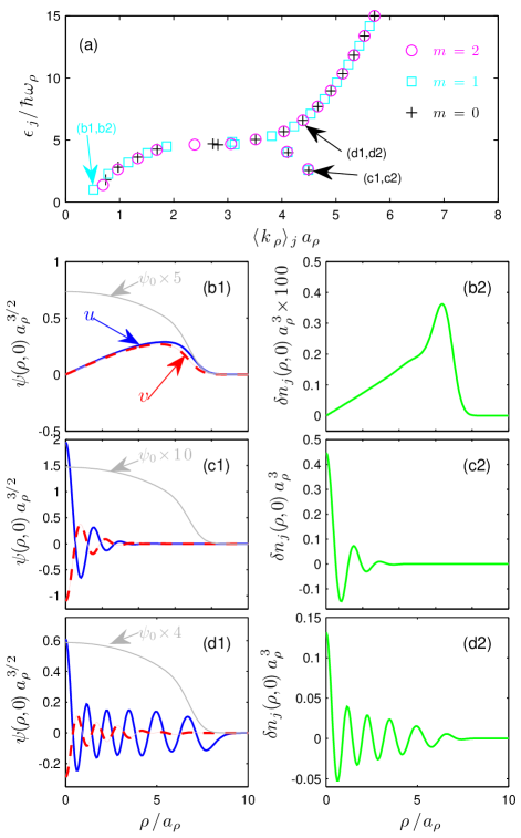
III.2.2 Phonon-Roton comparisons: density fluctuations
In Fig. 3 we compare a variety of quasiparticles including a phononlike mode, a roton mode, and a mode of similar effective linear momentum to the roton mode, but which resides in the non-rotonic background. In Fig. 3(a) we show a two-dimensional projection of the same data presented in Fig. 1, but limited to , and identify the modes we use for this comparison. In addition to examining the behavior of the and amplitudes of the quasiparticles individually, it is of interest to consider the density fluctuations, , where is the density operator, and we have assumed that is real. To leading order (taking to be small) the density fluctuations are given by
| (6) |
where is the density fluctuation amplitude associated with quasiparticle .
The and components of the phonon mode [Fig. 3(b1)] extend over the size of the condensate. Since the and are in-phase and almost equal, the associated density fluctuation is small [Fig. 3(b2)]. The roton mode [Fig. 3(c1)] has a short wavelength and is localized near the center of the condensate. Due to this localization, and because the and amplitudes of the rotons are out-of-phase, the associated density fluctuation has a peak value that is approximately 100 times larger than for the phonon mode. This difference in behavior occurs because of the momentum dependence of the interaction: the interaction between the condensate and its excitations is repulsive (i.e. suppressing density fluctuations) at long wavelengths, whereas it becomes attractive (i.e. enhancing density fluctuations) at wavelengths similar to (also see Fig. 5 of Ref. Blakie et al. (2013)). The enhanced density fluctuations of dipolar BECs has also been identified in Refs. Klawunn et al. (2011); Boudjemâa and Shlyapnikov (2013); Bisset and Blakie (2013). For comparison a mode with similar effective linear momentum to the roton mode, but not within the roton finger, is shown in Fig. 3(d1).
III.2.3 Development of fingers
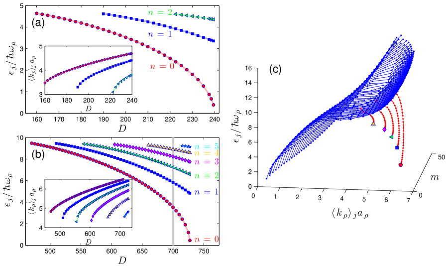
How the fingers emerge as DDI strength increases is considered in Fig. 4, where we present results for both and . The first fingers appear when is sufficiently large (for the fingers first emerge at and for they emerge at ). As increases the fingers decrease in energy and become longer (i.e. extend to over a larger range), and additional fingers emerge from the non-rotonic background. For a sufficiently large DDI strength the lowest () finger will fall to zero energy 444Usually the mode in the finger goes soft, but in special parameter regimes the condensate can take a bi-concave shape and a mode with softens Ronen et al. (2007) (also see Sec. III.4), and will become imaginary for , signaling that the condensate is dynamically unstable Ronen et al. (2006, 2007). For higher trap aspect ratios a greater number of fingers emerge before the onset of the dynamical instability, e.g. for we find that 3 fingers emerge by [see Fig. 4(a)]; for we find that 6 fingers emerge by [see Fig. 4(b)].
III.2.4 Finger dislocations: Phonon-Roton avoided crossings
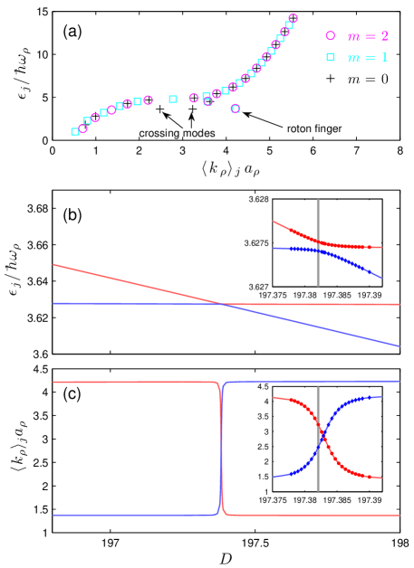
We also note that while the roton fingers are generally smooth functions of [see Figs. 1(d), 4(c)], for certain parameters we observe that particular roton modes dislocate from the finger by having a value that is significantly less than the other modes in that finger. The origin of these dislocations is avoided crossings between roton and phonon modes in the same subspace 555In our cylindrically symmetric treatment only modes in the same subspace can couple to each other.. We demonstrate this in Fig. 5 where we consider such a crossing that affects the roton. In Fig. 5(a) we show the roton mode dislocated from the finger in the midst of such a crossing, noting that the coupled phonon mode undergoes a matching dislocation to a higher momentum value.
To explore this crossing we vary the DDI strength. As increases the roton mode energy decreases, crossing the relevant phonon mode energy [see Fig. 5(b)]. Due to the coupling between these modes they undergo an avoided crossing during which the two modes hybridize, leading to a significant change in [Fig. 5(c)]. We emphasize that these avoided crossings can occur for any value of , however because the coupling between phonon and roton modes is weak they tend to occur in very narrow parameter regimes.
III.3 Relation to predictions of Jona-Lasinio et al. Jona-Lasinio et al. (2013b)
In Ref. Jona-Lasinio et al. (2013b) Jona-Lasinio et al. developed an analytic description of rotons in a trapped dipolar BEC. We briefly review their results and comment on its relationship to our full numerical treatment
A central idea of Ref. Jona-Lasinio et al. (2013b) is that after integrating out the tightly confined () degree of freedom, a local quasiparticle spectrum can be obtained for the in-plane coordinates, with the dependence arising from the variation of the condensate density. When the system exhibits a roton it emerges as a local minimum in at finite wavevector and at the trap center where the condensate density is highest. Expanding about this minimum to second order yields
| (7) |
where the energy minimum , the roton effective mass and the effective confinement frequency have been introduced. By re-quantizing Eq. (7) in momentum space, a spectrum of the form
| (8) |
is obtained, valid for , where .
Equation (8) should approximately describe the spectrum of our roton fingers. The physics used as the basis of this approach indeed qualitatively explains many of the results we observe, e.g. the localization in position and momentum space, and the harmonic oscillator like form of the roton wavefunctions in momentum space [see Fig. 2]. Our roton spectrum does exhibit a quadratic dependence on for small values of [e.g. see Fig. 1(d)], as predicted in Eq. (8), but this eventually crosses over to being approximately linear in for higher values. More generally, within the parameter regime we have studied (i.e. and pure dipolar BECs) we do not obtain quantitative agreement with the analytic spectrum. This can be seen from Fig. 4 where the fingers are not equally spaced in energy, as predicted by Eq. (8). This suggests that anharmonic corrections to Eq. (7) are significant. This anharmonicity is also evident because the higher energy modes (i.e. both higher and values) tend to shift to lower values of effective linear momentum [see insets to Figs. 4(a) and (b), and Figs. 1(c) and 4(c)]. This means that we cannot unambiguously assign a single to describe the rotons in the trapped system. Many of the anharmonic effects may be described by the full local quasiparticle spectrum introduced in Jona-Lasinio et al. (2013b) prior to making the quadratic approximation [i.e. Eq. 7] 666Private communication L. Santos.
III.4 Engineering the roton spectrum
In this section we consider the effect that a more general type of external potential has on the rotons in a dipolar BEC. To do this we add to our harmonic trap a Gaussian perturbing potential of the form
| (9) |
characterized by its strength and width . With this addition the combined potential is flat bottomed trap for small positive values of ( Baillie et al. (2010)) and becomes toroidal shaped for larger . We restrict our attention to perturbing potentials with much greater than the roton wavelength to ensure that the added potential smoothly modifies the condensate density profile rather than coupling strongly to the rotons and giving rise to strong density oscillations (e.g. see Yi and Pu (2006); Wilson et al. (2008)). We note that the effect of a barrier type perturbation in the direction was considered in Ref. Asad-uz Zaman and Blume (2010), and found to enrich the stability properties compared to the harmonically trapped case. Also Lu et al. Lu et al. (2010) examined the properties of a condensate in a box potential, and predict the formation of spatial density oscillations in the condensate due to the sharp edges of the potential.
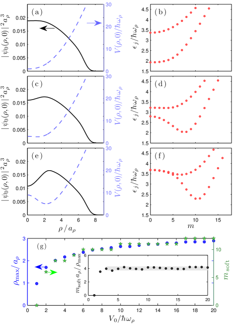
In Fig. 6 we show the condensate density and the roton fingers for a perturbation of width . For [Fig. 6(a)] the perturbing potential flattens the central condensate density, and causes the energies of the first few () modes to become almost degenerate [Fig. 6(b)]. As the strength of the perturbing potential increases the condensate develops a local minimum in density at trap center [Figs. 6(c), (e)]. When this occurs the roton fingers take a different character: the minimum energy in each roton finger occurs at a non-zero angular momentum projection () [Figs. 6(d), (f)]. In these cases the lowest energy roton propagates around the ring of maximum condensate density of radius , causing azimuthal fluctuations in the density of this ring. We also note that when the condensate density is sufficiently bi-concave [as in Fig. 6(e)], the first two fingers of the roton spectrum become degenerate, having the same energy and values, at low [as in Fig. 6(f)]. This appears to occur when the roton modes become well localized (spatially) in the dense condensate ring, and have a small amplitude at trap center.
We find that the value of the softest roton mode () is related to the radius at which the condensate density maximum occurs, and can be controlled by adjusting the height and width of the perturbation potential. Assuming that the softest mode causes an azimuthal buckling around the condensate ring at the roton wavelength we expect that . From this it follows that should increase proportional to if is assumed to be constant. This relationship is verified in Fig. 6(g) and inset.
IV Conclusion and outlook
In this paper we have explored the properties of rotons in pancake shaped dipolar BECs using fully three-dimensional solutions of the dipolar Gross-Pitaevskii and Bogoliubov-de Gennes equations. We have shown that rotons in the trapped system emerge as finger like chains when visualized using a momentum mapping technique, and that the quasiparticle modes are localized in both position and momentum space. Ronen et al. Ronen et al. (2007) established the connection between the condensate developing a modulated (bi-concave) density profile and the condensate becoming dynamically unstable due to a so called angular roton (i.e. a roton mode with ). They studied spontaneously occurring bi-concave states, i.e. those which occur in a pure harmonic trap in particular regions of interaction and trap geometry parameter space. For large aspect ratio traps, where the roton modes become clearly identifiable, such spontaneous bi-concave states only occur near the stability boundary (e.g. see Lu et al. (2010); Blakie et al. (2012)), and may be difficult to access experimentally. Importantly, our results show that imposing the density modulation using a perturbation also gives rise to angular rotons, and that these can be produced reasonably far from the stability boundary. Furthermore, by adjusting the perturbation, angular rotons with large angular momentum projection can be controllably engineered.
Important questions remain about the regime in which meanfield predictions may be quantitatively accurate. For the uniform dipolar BEC it has been shown that density fluctuations arising from the rotons can be significant at finite temperature Boudjemâa and Shlyapnikov (2013) (also see Ronen and Bohn (2007); *Lima2011a; *Ticknor2012a; *Bisset2012; *Lima2012a; *Pawlowski2013). Thus Bogoliubov theory may be limited to low temperatures , where is the condensation temperature Glaum et al. (2007).
Finally, we briefly discuss how aspects of rotons might be verified in experiments. One possibility is to measure the number fluctuations within finite-sized cells, as has been implemented in a number of experiments with pancake shaped condensates (e.g. see Hung et al. (2011)). It was shown in Ref. Bisset and Blakie (2013) that such measurements can be made sensitive to individual roton modes, revealing the location and size of the roton mode. Another possibility suggested in Ref. Wilson et al. (2009) is that the shape of the lowest energy mode can be revealed by quenching the system across the stability boundary (e.g. by making the -wave scattering length negative). In particular, this procedure reveals the presence of an angular roton through the development of a nontrivial angular distribution in the system post quench (c.f. the -wave symmetry of a dipolar BEC collapsing from a nearly spherical trap observed in Ref. Lahaye et al. (2008)). An alternative approach is to use some form of energy sensitive spectroscopy technique, such as collective mode or Bragg spectroscopy, which have already seen initial applications to dipolar BECs Bismut et al. (2010, 2012).
Acknowledgments
We acknowledge valuable feedback on the manuscript from L. Santos. This work was supported by the Marsden Fund of New Zealand (contracts UOO0924 and UOO1220). RB acknowledges support from the Graduate Research Committee, by means of the UO Publishing Bursary (Doctoral).
References
- Griesmaier et al. (2005) A. Griesmaier, J. Werner, S. Hensler, J. Stuhler, and T. Pfau, Phys. Rev. Lett. 94, 160401 (2005).
- Pasquiou et al. (2011) B. Pasquiou, G. Bismut, E. Maréchal, P. Pedri, L. Vernac, O. Gorceix, and B. Laburthe-Tolra, Phys. Rev. Lett. 106, 015301 (2011).
- Lu et al. (2011) M. Lu, N. Q. Burdick, S. H. Youn, and B. L. Lev, Phys. Rev. Lett. 107, 190401 (2011).
- Lu et al. (2012) M. Lu, N. Q. Burdick, and B. L. Lev, Phys. Rev. Lett. 108, 215301 (2012).
- Aikawa et al. (2012) K. Aikawa, A. Frisch, M. Mark, S. Baier, A. Rietzler, R. Grimm, and F. Ferlaino, Phys. Rev. Lett. 108, 210401 (2012).
- Baranov (2008) M. Baranov, Physics Reports 464, 71 (2008).
- Lahaye et al. (2009) T. Lahaye, C. Menotti, L. Santos, M. Lewenstein, and T. Pfau, Rep. Prog. Phys. 72, 126401 (2009).
- Santos et al. (2003) L. Santos, G. V. Shlyapnikov, and M. Lewenstein, Phys. Rev. Lett. 90, 250403 (2003).
- Corson et al. (2013a) J. P. Corson, R. M. Wilson, and J. L. Bohn, Phys. Rev. A 87, 051605 (2013a).
- Corson et al. (2013b) J. P. Corson, R. M. Wilson, and J. L. Bohn, Phys. Rev. A 88, 013614 (2013b).
- Jona-Lasinio et al. (2013a) M. Jona-Lasinio, K. Łakomy, and L. Santos, Phys. Rev. A 88, 025603 (2013a).
- Blakie et al. (2012) P. B. Blakie, D. Baillie, and R. N. Bisset, Phys. Rev. A 86, 021604 (2012).
- Bisset and Blakie (2013) R. N. Bisset and P. B. Blakie, Phys. Rev. Lett. 110, 265302 (2013).
- Wilson et al. (2008) R. M. Wilson, S. Ronen, J. L. Bohn, and H. Pu, Phys. Rev. Lett. 100, 245302 (2008).
- Wilson et al. (2010) R. M. Wilson, S. Ronen, and J. L. Bohn, Phys. Rev. Lett. 104, 094501 (2010).
- Ticknor et al. (2011) C. Ticknor, R. M. Wilson, and J. L. Bohn, Phys. Rev. Lett. 106, 065301 (2011).
- Nath and Santos (2010) R. Nath and L. Santos, Phys. Rev. A 81, 033626 (2010).
- Wilson et al. (2012) R. M. Wilson, C. Ticknor, J. L. Bohn, and E. Timmermans, Phys. Rev. A 86, 033606 (2012).
- Blakie et al. (2013) P. B. Blakie, D. Baillie, and R. N. Bisset, Phys. Rev. A 88, 013638 (2013).
- Klawunn et al. (2011) M. Klawunn, A. Recati, L. P. Pitaevskii, and S. Stringari, Phys. Rev. A 84, 033612 (2011).
- Note (1) We also note that in tight two-dimensional geometry, where the DDI is purely repulsive, rotons can emerge under conditions of strong interactions or high density, however these occur at a wavevector set by the inverse particle spacing, e.g. see Filinov et al. (2010); Hufnagl et al. (2011).
- Ronen et al. (2006) S. Ronen, D. C. E. Bortolotti, and J. L. Bohn, Phys. Rev. A 74, 013623 (2006).
- Ronen et al. (2007) S. Ronen, D. C. E. Bortolotti, and J. L. Bohn, Phys. Rev. Lett. 98, 030406 (2007).
- Asad-uz Zaman and Blume (2009) M. Asad-uz Zaman and D. Blume, Phys. Rev. A 80, 053622 (2009).
- Asad-uz Zaman and Blume (2010) M. Asad-uz Zaman and D. Blume, New J. of Phys. 12, 065022 (2010).
- Asad-uz Zaman and Blume (2011) M. Asad-uz Zaman and D. Blume, Phys. Rev. A 83, 033616 (2011).
- Martin and Blakie (2012) A. D. Martin and P. B. Blakie, Phys. Rev. A 86, 053623 (2012).
- Ticknor (2012a) C. Ticknor, Phys. Rev. A 86, 053602 (2012a).
- Jona-Lasinio et al. (2013b) M. Jona-Lasinio, K. Łakomy, and L. Santos, Phys. Rev. A 88, 013619 (2013b).
- Góral et al. (2000) K. Góral, K. Rza¸żewski, and T. Pfau, Phys. Rev. A 61, 051601 (2000).
- Morgan et al. (1998) S. A. Morgan, S. Choi, K. Burnett, and M. Edwards, Phys. Rev. A 57, 3818 (1998).
- Note (2) Because the symmetry axis of the trap corresponds to the direction along which the dipoles are polarized, the system is invariant under rotations about the axis, and is a good quantum number.
- Note (3) These general properties appear to hold while the condensate is in a normal state, i.e. has a smooth radial density profile with density maximum at trap center, which monotonically decreases with increasing (cf. Sec. III.4).
- Boudjemâa and Shlyapnikov (2013) A. Boudjemâa and G. V. Shlyapnikov, Phys. Rev. A 87, 025601 (2013).
- Note (4) Usually the mode in the finger goes soft, but in special parameter regimes the condensate can take a bi-concave shape and a mode with softens Ronen et al. (2007) (also see Sec. III.4).
- Note (5) In our cylindrically symmetric treatment only modes in the same subspace can couple to each other.
- Note (6) Private communication L. Santos.
- Baillie et al. (2010) D. Baillie, P. B. Blakie, and A. S. Bradley, Phys. Rev. A 82, 013626 (2010).
- Yi and Pu (2006) S. Yi and H. Pu, Phys. Rev. A 73, 061602 (2006).
- Lu et al. (2010) H.-Y. Lu, H. Lu, J.-N. Zhang, R.-Z. Qiu, H. Pu, and S. Yi, Phys. Rev. A 82, 023622 (2010).
- Ronen and Bohn (2007) S. Ronen and J. L. Bohn, Phys. Rev. A 76, 043607 (2007).
- Lima and Pelster (2011) A. R. P. Lima and A. Pelster, Phys. Rev. A 84, 041604 (2011).
- Ticknor (2012b) C. Ticknor, Phys. Rev. A 85, 033629 (2012b).
- Bisset et al. (2012) R. N. Bisset, D. Baillie, and P. B. Blakie, Phys. Rev. A 86, 033609 (2012).
- Lima and Pelster (2012) A. R. P. Lima and A. Pelster, Phys. Rev. A 86, 063609 (2012).
- Pawłowski et al. (2013) K. Pawłowski, P. Bienias, T. Pfau, and K. Rzążewski, Phys. Rev. A 87, 043620 (2013).
- Glaum et al. (2007) K. Glaum, A. Pelster, H. Kleinert, and T. Pfau, Phys. Rev. Lett. 98, 080407 (2007).
- Hung et al. (2011) C.-L. Hung, X. Zhang, L.-C. Ha, S.-K. Tung, N. Gemelke, and C. Chin, New J. Phys. 13, 075019 (2011).
- Wilson et al. (2009) R. M. Wilson, S. Ronen, and J. L. Bohn, Phys. Rev. A 80, 023614 (2009).
- Lahaye et al. (2008) T. Lahaye, J. Metz, B. Fröhlich, T. Koch, M. Meister, A. Griesmaier, T. Pfau, H. Saito, Y. Kawaguchi, and M. Ueda, Phys. Rev. Lett. 101, 080401 (2008).
- Bismut et al. (2010) G. Bismut, B. Pasquiou, E. Maréchal, P. Pedri, L. Vernac, O. Gorceix, and B. Laburthe-Tolra, Phys. Rev. Lett. 105, 040404 (2010).
- Bismut et al. (2012) G. Bismut, B. Laburthe-Tolra, E. Maréchal, P. Pedri, O. Gorceix, and L. Vernac, Phys. Rev. Lett. 109, 155302 (2012).
- Filinov et al. (2010) A. Filinov, N. V. Prokof’ev, and M. Bonitz, Phys. Rev. Lett. 105, 070401 (2010).
- Hufnagl et al. (2011) D. Hufnagl, R. Kaltseis, V. Apaja, and R. E. Zillich, Phys. Rev. Lett. 107, 065303 (2011).