11email: {angelini,patrignani,roselli}@dia.uniroma3.it 22institutetext: School of Information Technologies, The University of Sydney, Australia
22email: brillo@it.usyd.edu.au
Morphing Planar Graph Drawings Efficiently††thanks: Part of the research was conducted in the framework of ESF project 10-EuroGIGA-OP-003 GraDR “Graph Drawings and Representations”.
Abstract
A morph between two straight-line planar drawings of the same graph is a continuous transformation from the first to the second drawing such that planarity is preserved at all times. Each step of the morph moves each vertex at constant speed along a straight line. Although the existence of a morph between any two drawings was established several decades ago, only recently it has been proved that a polynomial number of steps suffices to morph any two planar straight-line drawings. Namely, at SODA , Alamdari et al. [1] proved that any two planar straight-line drawings of a planar graph can be morphed in steps, while steps suffice if we restrict to maximal planar graphs.
In this paper, we improve upon such results, by showing an algorithm to morph any two planar straight-line drawings of a planar graph in steps; further, we show that a morphing with steps exists between any two planar straight-line drawings of a series-parallel graph.
1 Introduction
A planar morph between two planar drawings of the same plane graph is a continuous transformation from the first drawing to the second one such that planarity is preserved at all times. The problem of deciding whether a planar morph exists for any two drawings of any graph dates back to , when Cairns [6] proved that any two straight-line drawings of a maximal planar graph can be morphed one into the other while maintaining planarity. In 1981, Grünbaum and Shephard [9] introduced the concept of linear morph, that is a continuous transformation in which each vertex moves at uniform speed along a straight-line trajectory. With this further requirement, however, planarity cannot always be maintained for any pair of drawings. Hence, the problem has been subsequently studied in terms of the existence of a sequence of linear morphs, also called morphing steps, transforming a drawing into another while maintaining planarity. The first result in this direction is the one of Thomassen [12], who proved that a sequence of morphing steps always exists between any two straight-line drawings of the same plane graph. Further, if the two input drawings are convex, this property is maintained throughout the morph, as well. However, the number of morphing steps used by the algorithm of Thomassen might be exponential in the number of vertices.
Recently, the problem of computing planar morphs gained increasing research attention. The case in which edges are not required to be straight-line segments has been addressed in [10], while morphs between orthogonal graph drawings preserving planarity and orthogonality have been explored in [11]. Morphs preserving more general edge directions have been considered in [5]. Also, the problem of “topological morphing”, in which the planar embedding is allowed to change, has been addressed in [2].
In a paper appeared at SODA 2013, Alamdari et al. [1] tackled again the original setting in which edges are straight-line segments and linear morphing steps are required. Alamdari et al. presented the first morphing algorithms with a polynomial number of steps in this setting. Namely, they presented an algorithm to morph straight-line planar drawings of maximal plane graphs with steps and of general plane graphs with steps, where is the number of vertices of the graph.
In this paper we improve upon the result of Alamdari et al. [1], providing a more efficient algorithm to morph general plane graphs. Namely, our algorithms uses linear morphing steps. Further, we provide a morphing algorithm with a linear number of steps for a non-trivial class of planar graphs, namely series-parallel graphs. These two main results are summarized in the following theorems.
Theorem 1.1.
Let and be two drawings of the same plane series-parallel graph . There exists a morph with steps transforming into .
Theorem 1.2.
Let and be two drawings of the same plane graph . There exists a morph with steps transforming into .
The rest of the paper is organized as follows. Section 2 contains preliminaries and basic terminology. Section 3 describes an algorithm to morph series-parallel graphs. Section 4 describes an algorithm to morph plane graphs. Section 5 provides geometric details for the morphs described in Sections 3 and 4. Finally, Section 6 contains conclusions and open problems.
2 Preliminaries
Planar graphs and drawings. A straight-line planar drawing (in the following simply drawing) of a graph maps vertices in to distinct points of the plane and edges in to non-intersecting open straight-line segments between their end-vertices. Given a vertex of a graph , we denote by the degree of in , that is, the number of vertices adjacent to . A planar drawing partitions the plane into connected regions called faces. The unbounded face is the external face. Also, determines a clockwise order of the edges incident to each vertex. Two planar drawings are equivalent if they determine the same clockwise ordering of the incident edges around each vertex and if they have the same external face. A planar embedding is an equivalence class of planar drawings. A plane graph is a planar graph with a given planar embedding.
Series-parallel graphs and their decomposition. A two-terminal series-parallel graph with source and target can be recursively defined as follows: (i) An edge joining two vertices and is a two-terminal series-parallel graph. Let and be two two-terminal series-parallel graphs with sources and , and targets and , respectively: (ii) The series composition of and obtained by identifying with is a two-terminal series-parallel graph with source and target ; and (iii) the parallel composition of and obtained by identifying with and with is a two-terminal series-parallel graph with source and target .
A biconnected series-parallel graph is defined as either a single edge or a two-terminal series-parallel graph with the addition of an edge, called root edge, joining and . In the following we deal with biconnected series-parallel graphs not containing multiple edges.
A series-parallel graph is a connected graph whose biconnected components are biconnected series-parallel graphs.
A biconnected series-parallel graph with root edge is naturally associated with an ordered binary tree rooted at , called decomposition binary tree. Each node of , with the exception of the one associated to , corresponds to a two-terminal series-parallel graph. Nodes of are of three types, S-nodes, P-nodes, and Q-nodes. Each Q-node represents a single edge. Each S-node represents the series composition of the two-terminal series-parallel graphs associated with its left and right subtrees. Finally, each P-node represents the parallel composition of the two-terminal series-parallel graphs associated with its left and right subtrees.
Observe that, a graph may admit more than one binary decomposition tree. Also, since all internal nodes of have degree three, if is rerooted at any other Q-node, corresponding to an edge , the obtained ordered binary tree defines a new set of compositions yielding the same graph with root edge .
Let be an embedded biconnected series-parallel graph and let be an edge incident to the external face of . Let be one of its binary decomposition trees rooted at . In order to have a unique decomposition tree of rooted at , we merge together all adjacent P-nodes and all adjacent S-nodes of . The order of the children of an S-node of reflects the order of the leaves of the subtree of induced by the merged S-nodes. Observe that, for each P-node of , the embedding of induces a circular order on the two-terminal series-parallel graphs corresponding to the children of . We order the children of according to such an ordering.
Morphs and Pseudo-Morphs. A (linear) morphing step , also referred to as linear morph, of two straight-line planar drawings and of a plane graph is a continuous transformation of into such that all the vertices simultaneously start moving from their positions in and, moving along a straight-line trajectory, simultaneously stop at their positions in so that no crossing occurs between any two edges during the transformation. A morph of two straight-line planar drawings into of a plane graph is a finite sequence of morphing steps that transforms into .
Let and be two vertices of such that edge belongs to and let be a straight-line planar drawing of . The contraction of onto results in a graph not containing and such that each edge of is replaced by an edge in , and a straight-line drawing of such that each vertex different from is mapped to the same point as in . In the rest of the paper, the contraction of an edge will be only applied if the obtained drawing is planar. The uncontraction of from in yields a straight-line planar drawing of . A morph in which contractions are performed, possibly together with other morphing steps, is a pseudo-morph.
Kernel of a vertex. Let be a vertex of and let be the graph obtained by removing and its incident edges from . Let be a planar straight-line drawing of . The kernel of in is the set of points such that straight-line segments can be drawn in connecting each point to each neighbor of in without intersecting any edge in .
3 Morphing Series-Parallel Graph Drawings in Steps
The aim of this section is to prove the following theorem:
Theorem 3.1.
Let and be two drawings of the same plane series-parallel graph . There exists a pseudo-morph with steps transforming into .
We will show in Section 3.1 an algorithm that, given two drawings of the same biconnected plane series-parallel graph , computes a pseudo-morph transforming one drawing into the other. Then, in Section 3.5 we extend this approach to simply-connected series-parallel graphs, thus proving Theorem 3.1.
3.1 Biconnected Series-Parallel Graphs
In this section, we show an algorithm to construct a pseudo-morph transforming one drawing of a biconnected plane series-parallel graph into another.
Our approach consists of morphing any drawing of a biconnected plane series-parallel graph into a “canonical drawing” of in a linear number of steps. As a consequence, any two drawings and of can be transformed one into the other in a linear number of steps, by morphing to and to .
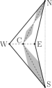
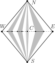
A canonical drawing of a biconnected plane series-parallel graph is defined as follows. The decomposition tree of is traversed top-down and a suitable geometric region of the plane is assigned to each node of ; such a region will contain the drawing of the series-parallel graph associated with . The regions assigned to the nodes of are similar to those used in [4, 3] to construct monotone drawings. Namely, we define three types of regions: Left boomerangs, right boomerangs, and diamonds. A left boomerang is a quadrilateral with vertices , and such that is inside triangle , where and (see Fig. 1). A right boomerang is defined symmetrically, with playing the role of , and vice versa (see Fig. 1). A diamond is a convex quadrilateral with vertices and , where . Observe that a diamond contains a left boomerang and a right boomerang , where , , , and (see Fig. 1).


We assign boomerangs (either left or right, depending on the embedding of ) to S-nodes and diamonds to P- and Q-nodes, as follows.
First, consider the Q-node corresponding to the root edge of . Draw edge as a segment between points and . Also, if is adjacent to an S-node , then assign to the left boomerang or the right boomerang , depending on the embedding of ; if is adjacent to a P-node , then associate to the diamond .
Then, consider each node of according to a top-down traversal.
If is an S-node (see Fig. 1), let be the boomerang associated with it and let be the angle . We associate diamonds to the children of as follows. Consider the midpoint of segment . Subdivide into segments with the same length and into segments with the same length. Enclose each of such segments , for , into a diamond , with , and associate it with child of .
If is a P-node (see Fig. 1), let be the diamond associated with it. Associate boomerangs and diamonds to the children of as follows. If a child of is a Q-node, then left boomerangs are associated to , right boomerangs are associated to , and a diamond is associated to . Otherwise, right boomerangs are associated to all of . We assume that a child of that is a Q-node exists, the description for the case in which no child of is a Q-node being similar and simpler. We describe how to associate left boomerangs to the children of . Consider the midpoint of segment and consider equidistant points on segment . Associate each child , with , to the quadrilateral . Right boomerangs are associated to in a symmetric way. Finally, associate to any diamond such that , is any point between and , and is any point between and .
If is a Q-node, let be the diamond associated with it. Draw the edge corresponding to as a straight-line segment between and .
Observe that the above described algorithm constructs a drawing of , that we call the canonical drawing of . We now argue that no two edges and intersect in the canonical drawing of . Consider the lowest common ancestor of the Q-nodes and of representing and , respectively. Also, consider the children and of such that the subtree of rooted at contains , for . Such children are associated with internally-disjoint regions of the plane. Since the subgraphs and of corresponding to and , respectively, are entirely drawn inside such regions, it follows that and do not intersect except, possibly, at common endpoints.
In order to construct a pseudo-morph of a straight-line planar drawing of into its canonical drawing , we do the following: (i) We perform a contraction of a vertex of into a neighbor of , hence obtaining a drawing of a graph with vertices; (ii) we inductively construct a pseudo-morph from to the canonical drawing of ; and (iii) we uncontract and perform a sequence of morphing steps to transform into the canonical drawing of .
We describe the three steps in more detail.
3.2 Step 1: Contract a Vertex
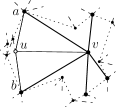
Let be the decomposition tree of rooted at some edge incident to the outer face of . Consider a P-node such that the subtree of rooted at does not contain any other P-node. This implies that all the children of , with the exception of at most one Q-node, are S-nodes whose children are Q-nodes. Hence, the series-parallel graph associated to is composed of a set of paths connecting its poles and . Let and be two paths joining and and such that their union is a cycle not containing other vertices in its interior (see Fig. 2). Such paths exist given that the “rest of the graph” with respect to is in the outer face of , given that the root of is incident to the outer face of . Internally triangulate by adding dummy edges (dashed edges of Fig. 2). Cycle and the added dummy edges yield a drawing of a biconnected outerplane graph which, hence, has at least two vertices of degree two.


We distinguish two cases depending on the existence of a degree- vertex different from and .
- Case 1 (there exists a vertex of degree different from and ).
-
Assume, without loss of generality, that belongs to . Since is internally triangulated, both the neighbors and of belong to , and they are joined by a dummy edge. We obtain from by contracting onto one of its neighbors, while preserving planarity (see Figs. 2 and 2). Either contains more than two edges (Case 1.1) or consists of exactly two edges, namely and . If the latter case holds, either edge exists in (Case 1.2) or not (Case 1.3). In the three cases we do the following.
- Case 1.1)
-
Path is replaced in with a path that contains edge and does not contain vertex .
- Case 1.2)
-
Graph is set as .
- Case 1.3)
-
Path is replaced in with edge .
- Case 2 (the only two vertices of degree in are and ).
-
In this case, one of the two vertices and adjacent to has degree , say (since the removal of and its incident edges would yield another biconnected outerplane graph with two vertices of degree , namely and one of and ). We obtain from by contracting onto . Let be the neighbor of and different from . Since the edges incident to are contained into triangles and during the contraction, planarity is preserved (see Figs. 2 and 2). Let be the path composed of edge and of the subpath of between and , and let be the subpath of between and . Observe that contains edge and does not contain vertex .
Tree is obtained from by performing the local changes described hereunder, with respect to the above cases.
- Case 1.
-
Let and be the nodes of corresponding to paths and . Note that is an S-node, as and . The two Q-nodes that are children of and that correspond to edges and are removed in .


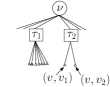

Figure 3: Construction of starting from in Case 1. (a–b) and , respectively, in Case 1.1. (c–d) and , respectively, in Case 1.3. - Case 2.
-
Let and be the nodes of corresponding to paths and , and let be the parent of . Note that and are S-nodes, as . First, the Q-nodes corresponding to edges and are removed from the children of , and a Q-node (corresponding to edge ) is added to . We distinguish the cases in which has more than two children in (Case 2.1) and when has exactly two children in (Case 2.2).
- Case 2.1)
-
An S-node and a P-node are introduced in , in such a way that (i) is a child of , (ii) the Q-node corresponding to and are children of , (iii) and are children of , and (iv) is a child of . See Figs. 4 and 4.


Figure 4: Construction of starting from in Case 2. (a–b) and , respectively, in Case 2.1. (c–d) and , respectively, in Case 2.2. - Case 2.2)
3.3 Step 2: Recursive Call
Let be the drawing of the graph obtained after the contraction of vertex performed in Case 1 or in Case 2.
Inductively construct a morphing from to the canonical drawing of in steps, where is a constant.
3.4 Step 3: Uncontract Vertex and Construct a Canonical Drawing of
We describe how to obtain from by uncontracting and performing a constant number of morphing steps. The description follows the cases discussed in Appendix 3.2.
- Case 1 (there exists a vertex of degree different from and ).
-
- Case 1.1)
-
This case is discussed in Section 3.1.
- Case 1.2 and Case 1.3)
-
Note that and coincide, except for the fact that: (i) contains one boomerang more than (the one associated to ) inside the diamond associated to , (ii) might not contain the diamond associated to the Q-node corresponding to edge (in Case 1.3), and (iii) the boomerangs inside the diamond associated to have a different drawing in and . Drawing is illustrated in Fig. 5, drawing in Case 1.2 is illustrated in Fig. 5, drawing in Case 1.3 is illustrated in Fig. 5.
Since edge exists in , its drawing in is the straight-line segment between the points and of a diamond . Also, the drawing of in lies inside a boomerang with and .
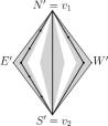
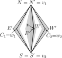
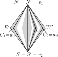
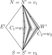
Figure 5: Construction of from when either Case 1.2 or Case 1.3 applied. (a) . The diamond associated to edge and the boomerangs associated to the children of are light-grey. (b) Two points and are selected on , creating a (dark gray) boomerang associated to , and vertex is moved to the midpoint of . (c) in Case 1.2, where edge exists in . (d) in Case 1.3. In order to construct a pseudo-morph from to , initially place points and on segment , on the same side with respect to segment (in Case 1.2, the side depends on the order of the children of in ). With one morphing step, move to the midpoint of segment (see Fig. 5).
Consider the children of in that are not Q-nodes, with , and note that the drawing of each is composed of two straight-line segments and . With a second morphing step, move the vertex of lying on , for each , and vertex along the line through till reaching their positions in . In the same morphing step, for each , the vertices on the path between and are moved as convex combination of the movements of and , and the vertices on the path between and are moved as linear combination of the movements of and . Hence, at the end of the morphing step, also such vertices reach their positions in (see Figs. 5 and 5).
- Case 2 (the only two vertices of degree in are and ).
-
- Case 2.1)
-
Note that and coincide, except for the drawing of , , , and .
Namely, and are drawn in in two boomerangs and lying inside the diamond associated to (see Fig. 6), while and are drawn in in two boomerangs and lying inside a diamond associated to , that lies inside a boomerang associated to (with ), that lies inside the diamond associated to (see Fig. 6).
Note that, since has two children in , vertex is placed on the midpoint of segment , that is, .
Let and be the vertices of and , respectively, placed on the midpoints and of segments and .
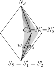
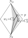
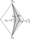
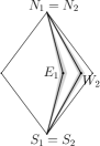
Figure 6: Construction of from when Case applied. (a) . The boomerang associated to is light-grey, the diamonds associated to and to the Q-node corresponding to are dark-grey, and the boomerangs associated to and are white. (b) Vertices and are moved to points and , and is moved to a point of . (c) Vertex is uncontracted from and moved to a point of . (d) . The boomerangs associated to and are light-grey. With one morphing step, move to any point on , move to any point on , and move to any point on segment (see Fig. 6). In the same morphing step, for each two vertices in , , , and , say and , the vertices lying on segment are moved as linear combination of the movements of and . Hence, at the end of the morphing step, all these vertices still lie on .
Next, with one morphing step, uncontract from and move it to any internal point on segment (see Fig. 6). In the same morphing step, the vertices lying on segment are moved as linear combination of the movements of and .
Further, perform the same operation as in Case 1.1 to redistribute the vertices of on and , and the vertices of on and . After this step, for each child of , the vertex of lying on segment in lies on also in the current drawing.
Finally, perform the same operation as in Case 1.2 to move the vertex of each child of to its final position (on segment ) in . In the same morphing step, the vertices on the path between and are moved as linear combination of the movements of and , and the vertices on the path between and are moved as linear combination of the movements of and . Hence, at the end of the morphing step, also such vertices reach their positions in .
- Case 2.2)
-
Note that and coincide, except for the drawing of , , , and .
Namely, and are drawn in in two boomerangs (associated to and ) lying inside the diamond associated to (see Fig. 7), that lies inside the boomerang associated to . Also and are drawn in in two boomerangs lying inside a diamond (associated to ) that lies inside the boomerang associated to (see Fig. 7). However, the boomerang associated to in has one diamond less than in , since in it also contains the diamond associated to edge . Also, the vertices in the boomerangs associated to and have different positions in and in , since vertex is not present in .
With three morphing steps analogous to those performed in Case 1.1, we redistribute the vertices inside the boomerang associated to in such a way that the vertex lying on the midpoint of is the same in and in . Note that, after these steps, the diamonds associated to and to edge lie on the same segment, either or , say , and that the vertices lying on segment already are at their final position in . Then, with three morphing steps analogous to those performed in Case 2.1, we uncontract and collapse the two diamonds associated to and to into a single diamond. Then, with one morphing step (analogous to one of the steps performed in Case ), we move the vertices lying on segment till they reach their final position in .
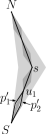
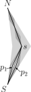
Figure 7: Construction of from when Case applied. (a) . The boomerang associated to is light-grey, the diamonds associated to the children of , including and the Q-node corresponding to are dark-grey, and the boomerangs associated to and are white. (b) .
3.5 Simply-Connected Series-Parallel Graphs
In this section we show how, by preprocessing the input drawings and of any series-parallel graph , the algorithm presented in Section 3.1 can be used to compute a pseudo-morph . The idea is to augment both and to two drawings and of a biconnected series-parallel graph , compute the morph , and obtain by restricting to the vertices and edges of .
This augmentation is performed on by repeatedly applying the following lemma.
Lemma 1.
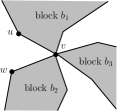
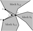
Let be a cut-vertex of a plane series-parallel graph with blocks. Let and be two consecutive edges in the circular order around such that belongs to block of and belongs to block of . The graph obtained from by adding a vertex and edges and is a plane series-parallel graph with blocks.
Proof: First, observe that by adding , , and to , blocks and are merged together into a single block of (see Figs. 8 and 8). Hence, the number of blocks of is . It remains to show that is a series-parallel graph.
Assume for a contradiction that is not a series-parallel graph. It follows that contains a subdivision of the complete graph on four vertices , i.e., there is a set of four vertices of such that any two of them are joined by three vertex-disjoint paths. Observe that the vertices in cannot belong to different blocks of . Further, since is a series-parallel graph, the vertices in belong to . Since has degree two, ; hence, the vertices in are also vertices of . This gives a contradiction since: (i) The vertices in cannot all belong to , as otherwise would not be series-parallel, contradicting the hypothesis; (ii) the vertices in cannot all belong to , for the same reason; and (iii) the vertices in cannot belong both to and , as otherwise there could not exist three vertex-disjoint paths joining them in , contradicting the hypothesis that contains a subdivision of .
Observe that, when augmenting to , both and can be augmented to two planar straight-line drawings and of by placing vertex suitably close to and with direct visibility to vertices and , as in the proof of Fáry’s Theorem [8]. By repeatedly applying such an augmentation we obtain a biconnected series-parallel graph and its drawings and , whose number of vertices and edges is linear in the size of . Hence, the algorithm described in Section 3.1 can be applied to obtain a pseudo-morph , thus proving Theorem 3.1. We will show in Section 5 how to obtain a morph starting from the pseudo-morph computed in this section.
4 Morphing Plane Graph Drawings in Steps
In this section we prove the following theorem.
Theorem 4.1.
Let and be two drawings of the same plane graph . There exists a pseudo-morph with steps transforming into .
4.0.1 Preliminary definitions
Let be a planar straight-line drawing of a plane graph . A face of is empty in if it is delimited by a simple cycle. Consider a vertex of and let and be two of its neighbors. Vertices and are consecutive neighbors of if no edge appears between edges and in the circular order of the edges around in . Let be a vertex with such that each face containing on its boundary is empty. We say that is contractible [1] if, for each two neighbors and of , edge exists in if and only if and are consecutive neighbors of . We say that is quasi-contractible if, for each two neighbors and of , edge exists in only if and are consecutive neighbors of . In other words, no edge exists between non-consecutive neighbors of a contractible or quasi-contractible vertex; also, each face incident to a contractible vertex is delimited by a -cycle, while a face incident to a quasi-contractible vertex might have more than three incident vertices. We have the following.
Lemma 2.
Every planar graph contains a quasi-contractible vertex.
Proof: Let be a planar drawing of a graph . Add vertices , , and so that the triangle composed by these vertices completely encloses , and augment the obtained drawing to the drawing of a maximal plane graph by adding dummy edges. Since is maximal plane, it contains a contractible vertex (different from , , and ), as shown in [1]. Since is contractible in , it is either contractible or quasi-contractible in , as the edges incident to a vertex in are at most those of .
Further, given a neighbor of , we say that is -contractible onto in if: is quasi-contractible, and the contraction of onto in results in a straight-line planar drawing of .
4.0.2 The algoritm
We describe the main steps of our algorithm to pseudo-morph a drawing of a plane graph into another drawing of .
First, we consider a quasi-contractible vertex of , that exists by Lemma 2. Second, we compute a pseudo-morph with steps of into a drawing of and a pseudo-morph with steps of into a drawing of , such that is -contractible onto the same neighbor both in and in . We will describe later how to perform these pseudo-morphs. Third, we contract onto both in and in , hence obtaining two drawings and of a graph with vertices. Fourth, we recursively compute a pseudo-morph transforming into . This completes the description of the algorithm for constructing a pseudo-morphing transforming into . Observe that the algorithm has steps, thus proving Theorem 4.1. Namely, as it will be described later, steps suffice to construct pseudo-morphings of and into drawings and of , respectively, such that is -contractible onto the same neighbor both in and in . Further, two steps are sufficient to contract onto in both and , obtaining drawings and , respectively. Finally, the recursion on and takes steps. Thus, . We will show in Section 5 how to obtain a morph starting from the pseudo-morph computed in this section.
We remark that our approach is similar to the one proposed by Alamdari et al. [1]. In [1] and are augmented to drawings of the same maximal planar graph with vertices; then, Alamdari et al. show how to construct a morphing in steps between two drawings of the same -vertex maximal planar graph. This results in a morphing between and with steps. Here, we also augment and to drawings of maximal planar graphs. However, we only require that the two maximal planar graphs coincide in the subgraph induced by the neighbors of . Since this can be achieved by adding a constant number of vertices to and , namely one for each of the at most five faces is incident to, our morphing algorithm has steps.
4.0.3 Making -contractiblle
Let be a quasi-contractible vertex of . We show an algorithm to construct a pseudo-morph with steps transforming any straight-line planar drawing of into a straight-line planar drawing of such that is -contractible onto any neighbor . If has degree , then it is contractible into its unique neighbor in , and there is nothing to prove.
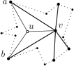
In order to transform into , we use a support graph and its drawing , initially set equal to and , respectively. The goal is to augment and so that becomes a contractible vertex of . In order to do this, we have to add to an edge between any two consecutive neighbors of . However, the insertion of these edges might not be possible in , as it might lead to a crossing or to enclose some vertex inside a cycle delimited by and by two consecutive neighbors of (see Fig. 9).
Let and be two consecutive neighbors of . If the closed triangle does not contain any vertex other than , , and , then add edge to and to as a straight-line segment. Otherwise, proceed as follows. Let be the drawing of a plane graph obtained by adding a vertex and the edges , , and to and to , in such a way that the resulting drawing is straight-line planar and each face containing on its boundary is empty. As in the proof of Fáry’s Theorem [8], a position for with such properties can be found in , suitably close to . See Fig. 9 for an example.


Augment to the drawing of a maximal plane graph by first adding three vertices , , and to , so that triangle completely encloses the rest of the drawing, and then adding dummy edges [7] till a maximal plane graph is obtained. If edge has been added in this augmentation (this can happen if and share a face not having on its boundary), subdivide in (namely, replace edge with edges and , placing along the straight-line segment connecting and ) and triangulate the two faces vertex is incident to.
Next, apply the algorithm described in [1], that we call Convexifier, to construct a morphing of into a drawing of in which polygon is convex. The input of algorithm Convexifier consists of a planar straight-line drawing of a plane graph and of a set of at most five vertices of inducing a biconnected outerplane graph not containing any other vertex in its interior in . The output of algorithm Convexifier is a sequence of linear morphing steps transforming into a drawing of in which the at most five input vertices bound a convex polygon. Since, by construction, vertices satisfy all such requirements, we can apply algorithm Convexifier to and to , hence obtaining a morphing with steps transforming into the desired drawing (see Fig. 9).
Let be the drawing of obtained by restricting to vertices and edges of . Since is a convex polygon containing no vertex of in its interior, edge can be removed from and an edge can be introduced in , so that the resulting drawing is planar and cycle does not contain any vertex in its interior (see Fig. 9).
Once edge has been added to (either in or after the described procedure transforming into ), if then is both -contractible and -contractible. Otherwise, consider a new pair of consecutive vertices of not creating an empty triangular face with , if any, and apply the same operations described before.
Once every pair of consecutive vertices has been handled, vertex is contractible in . Let be the current drawing of . Augment to the drawing of a triangulation (by adding three vertices and a set of edges), contract onto a neighbor such that is -contractible (one of such neighbors always exists, given that is contractible), and apply Convexifier to the resulting drawing and to the neighbors of to construct a morphing to a drawing in which the polygon defined by such vertices is convex. Drawing of in which is -contractible for any neighbor of is obtained by restricting to the vertices and the edges of . We can now contract onto in and recur on the obtained graph (with vertices) and drawing.
It remains to observe that, given a quasi-contractible vertex , the procedure to construct a pseudo-morph of into consists of at most executions of Convexifier, each requiring a linear number of steps [1]. As , the procedure to pseudo-morph into has steps. This concludes the proof of Theorem 4.1.
5 Transforming a Pseudo-Morph into a Morph
In this section we show how to obtain an actual morph from a given pseudo-morph , by describing how to compute the placement and the motion of any vertex that has been contracted during . By applying this procedure to Theorems 3.1 and 4.1, we obtain a proof of Theorems 1.1 and 1.2.
Let be a drawing of a graph and let be a pseudo-morph that consists of the contraction of a vertex of onto one of its neighbors , followed by a pseudo-morph of the graph , and then of the uncontraction of .
The idea of how to compute from is the same as in [1]: Namely, morph is obtained by recursively converting into a morph ; modifying to a morph obtained by adding vertex (and its incident edges) to each drawing of , in a suitable position; replacing the contraction of onto , performed in , with a linear morph that moves from its initial position in to its position in the first drawing of ; and replacing the uncontraction of , performed in , with a linear morph that moves from its position in the last drawing of to its final position in . Note that, in order to guarantee the planarity of when adding to any drawing of in order to obtain , vertex must lie inside its kernel. Since vertex lies in the kernel of (as is adjacent to all the neighbors of in ), we achieve this property by placing suitably close to , as follows.
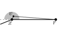
At any time instant during , there exists an such that the disk centered at with radius does not contain any vertex other than . Let be the minimum among the during . We place vertex at a suitable point of a sector of according to the following cases.
- Case 10: has degree in .
-
Sector is defined as the intersection of with the face containing in . See Fig. 10.
- Case 10: has degree in .
-
Sector is defined as the intersection of with the face containing in and with the halfplane defined by the straight-line passing through and , and containing in . See Fig. 10.
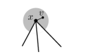
Otherwise, in . Let and be the
two edges such that
, , and are clockwise consecutive around
in .
Observe that edges and exist in . Assume
that , , and
are not collinear in any drawing of , as otherwise we can slightly
perturb such a drawing without
compromising the planarity of . Let be the angle in any
intermediate drawing of .


By exploiting the techniques shown in [1], the motion of can be computed according to the evolution of over , thus obtaining a planar morph . For convenience, we report hereunder the statement of Lemma 5.2 of [1], showing that a contracted vertex can be placed and moved according to the evolution of a sector defined on one of its neighbors lying in the kernel.
Lemma 3.
([1]) Let be straight-line planar drawings of a -gon on vertices in clockwise order such that the morph is planar and vertex is inside the kernel of the polygon at all times during the morph. Then we can augment each drawing to a drawing by adding vertex at some point inside the kernel of the polygon in , and adding straight line edges from to each of in such a way that the morph is planar.
Observe that, in the algorithm described in Section 4, the vertex onto which has been contracted might be not adjacent to in . However, since a contraction has been performed, is adjacent to in one of the graphs obtained when augmenting during the algorithm. Hence, a morph of can be obtained by applying the above procedure to the pseudo-morph computed on this augmented graph and by restricting it to the vertices and edges of .
6 Conclusions and Open Problems
In this paper we studied the problem of designing efficient algorithms for morphing two planar straight-line drawings of the same graph. We proved that any two planar straight-line drawings of a series-parallel graph can be morphed with linear morphing steps, and that a planar morph with linear morphing steps exists between any two planar straight-line drawings of any planar graph.
It is a natural open question whether the bounds we presented are optimal or not. We suspect that planar straight-line drawings exist requiring a linear number of steps to be morphed one into the other. However, no super-constant lower bound for the number of morphing steps required to morph planar straight-line drawings is known.
It would be interesting to understand whether our techniques can be extended to compute morphs between any two drawings of a partial planar -tree with a linear number of steps. We recall that, as observed in [1], a linear number of morphing steps suffices to morph any two drawings of a maximal planar -tree.
References
- [1] Alamdari, S., Angelini, P., Chan, T.M., Di Battista, G., Frati, F., Lubiw, A., Patrignani, M., Roselli, V., Singla, S., Wilkinson, B.T.: Morphing planar graph drawings with a polynomial number of steps. In: SODA ’13. pp. 1656–1667 (2013)
- [2] Angelini, P., Cortese, P.F., Di Battista, G., Patrignani, M.: Topological morphing of planar graphs. In: Tollis, I.G., Patrignani, M. (eds.) GD ’08. LNCS, vol. 5417, pp. 145–156 (2008)
- [3] Angelini, P., Didimo, W., Kobourov, S., Mchedlidze, T., Roselli, V., Symvonis, A., Wismath, S.: Monotone drawings of graphs with fixed embedding. Algorithmica pp. 1–25 (2013)
- [4] Angelini, P., Colasante, E., Di Battista, G., Frati, F., Patrignani, M.: Monotone drawings of graphs. J. of Graph Algorithms and Appl. 16(1), 5–35 (2012), special Issue from GD ’10
- [5] Biedl, T.C., Lubiw, A., Spriggs, M.J.: Morphing planar graphs while preserving edge directions. In: Healy, P., Nikolov, N.S. (eds.) GD’05. LNCS, vol. 3843, pp. 13–24 (2005)
- [6] Cairns, S.S.: Deformations of plane rectilinear complexes. American Math. Monthly 51, 247–252 (1944)
- [7] Chazelle, B.: Triangulating a simple polygon in linear time. Discrete & Computational Geometry 6(5), 485–524 (1991)
- [8] Fáry, I.: On straight line representation of planar graphs. Acta Univ. Szeged. Sect. Sci. Math. 11, 229–233 (1948)
- [9] Grunbaum, B., Shephard, G.: The geometry of planar graphs. Cambridge University Press (1981), http://dx.doi.org/10.1017/CBO9780511662157.008
- [10] Lubiw, A., Petrick, M.: Morphing planar graph drawings with bent edges. Electronic Notes in Discrete Mathematics 31, 45–48 (2008)
- [11] Lubiw, A., Petrick, M., Spriggs, M.: Morphing orthogonal planar graph drawings. In: SODA ’06. pp. 222–230. ACM (2006)
- [12] Thomassen, C.: Deformations of plane graphs. J. Comb. Th., Series B 34, 244–257 (1983)