Waveguide QED: controllable channel from quantum interference
Abstract
We study a waveguide QED system with a rectangular waveguide and a two-level system (TLS) inside, where the transverse modes TMmn define the quantum channels of guided photons. It is discovered that the loss of photons in the TM11 channel into the others can be overcome by replacing it with a certain coherent superposition of TMmn channels, which is named as the controllable channel (CC) as the photons in CC can be perfectly reflected or transmitted by the TLS, and never lost into the other channels. The dark state emerges when the photon is incident from one of the scattering-free channels (SFCs) orthogonal to CC. The underlying physics mechanism is the multi-channel interference associated with Fano resonance.
pacs:
42.50.Gy, 42.50.Ct, 03.65.NkIn a fully-quantum network based on single photon carriers to process quantum information, the essential task is to coherently control photon propagation by a local quantum node key1-Harris1998 ; key2-Ham2000 ; key3-Birnbaum2005 ; key4-Bajcsy2009 ; key5-Shen ; ShenPRA ; Hu2007 ; key6-Zhou2008 ; key7-Gong2008 ; ShiPRB ; LiaoPRA ; AMO2010 ; key8-Chang2007 ; key9-Hwang2009 ; key10-Tsoi2009 ; key11-Shi2011 ; key12-Zhang2012 ; key13-Wang2012 ; key14-Aoki2009 ; key15-Zhou-arxiv . To this end, a hybrid system consisting of a one-dimensional (1D) waveguide coupled to a two-level system (TLS) is extensively studied for physical implementation of the quantum node acting as a quantum switch key4-Bajcsy2009 ; key5-Shen ; ShenPRA ; Hu2007 ; key6-Zhou2008 ; key7-Gong2008 ; ShiPRB ; LiaoPRA ; AMO2010 or a single photon transistor key8-Chang2007 ; key9-Hwang2009 . With the single mode approximation for a waveguide with infinitesimal cross section, the total reflection of single photons by the TLS was found to be responsible for the dominant functions of quantum devices.
However, a realistic waveguide with a finite cross section necessarily possesses transverse modes. Thus, photons guided in the realistic waveguide may be in different quantum channels defined by transverse modes. Each transverse mode has a cut-off frequency for the corresponding guiding mode. To demonstrate multi-channel effects on single-photon scattering, Ref.Huang-arxiv made an approximation using two modes and a quadratic dispersion relation, and showed that the guided photon cannot be totally reflected due to the loss from one mode to the other. In other words, the quantum device oriented functions we desire can not be well achieved . In order to overcome such multi-channel loss, we will revisit the waveguide QED by considering a realistic hybrid system without any over-approximation.
In this letter, we study single-photon scattering by a TLS locally embedded in a waveguide of finite rectangular cross section. In our approach, both the real dispersion relation and multi- channel effects are exactly taken into account. As for the multi-channel induced loss, we find that there exists a unique controllable channel (CC) defined by a particular superposition of the transverse magnetic modes TMmn, in which the guided photons can be well controlled by the TLS since the guided photons in the complementary channels orthogonal to CC are completely decoupled from the TLS. Such a scattering free channel (SFC) behaves as the dark state to support the electromagnetically induced transparency (EIT). The controllable channel and all SFCs make up the whole single-excitation Hilbert space of the waveguide QED system. In the controllable channel the quantum interference between the incident wave and the scattered one leads to a Fano resonanceFano , so that the photon could be perfectly reflected or enabled to be completely transmitted by the TLS. Therefore, using the CC to guide photons we can well exploit the quantum device oriented functions of the TLS in a realistic waveguide.
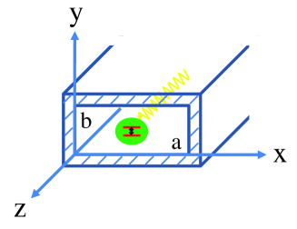
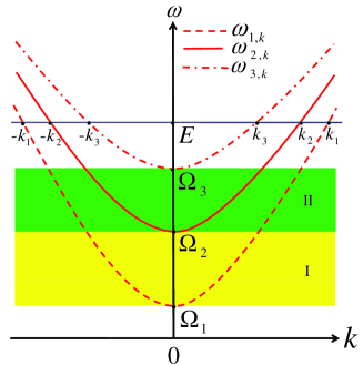
Photon scattering by a TLS within a rectangular waveguide.We consider a waveguide of rectangular cross section with area , as shown in Fig.1. The guiding modes in such a realistic waveguide are labeled by , with the transverse magnetic mode TMmn (standing wave-numbers in the cross section are , ) and the propagating wavenumber along the -direction. Each transverse mode has the cut-off frequency (the unit is used). According to the ascending order of the cut-off frequencies, we replace with its sequence number , that is denote the transverse modes TM11, TM31,TM13…. respectively. The dispersion relation of the guiding modes is given by , as plotted in Fig.2. The TLS of transition frequency is located at , whose ground (excited) state is denoted by (). The dipole oriented along the z-direction couples the TM electric field. With the atomic rising (lowering) operator (), the total Hamiltonian of the hybrid system is given by the free part
| (1) |
and the dipole interaction
| (2) |
Here, the mode-dependent coupling strength reads
| (3) |
with , . The matrix element of the dipole transition is set to be real. Note that the coupling strength vanishes for even integers or .
We now consider single-photon scattering in the waveguide QED system. For a single photon initially in the state with energy , the scattering state assumes the form
| (4) |
which ensures the conservation of the excitation number in the single excitation subspace. Here, represents the TLS in the ground state and the waveguide field in vacuum. The amplitudes and are obtained from the Lippmann Schwinger equation The elements of the scattering matrix can be obtained from the scattering state as
| (5) |
where , and are the real and imaginary parts of the self-energy respectively. For detailed calculations of the scattering matrix element, see the supplemental material.
Single channel scattering and its loss. It is known that a TLS acts as a quantum switch for single photons confined in a single-mode waveguide key5-Shen ; key6-Zhou2008 ; key7-Gong2008 ; key8-Chang2007 . To keep a photon propagating in a single quantum channel, this realistic waveguide is required that: 1) The cross section must be so small that is large enough; 2) The energy of the input photon is below the cutoff frequency , i.e. . Under these conditions, Eq.(5) gives the reflection amplitude in the TM11 mode as
| (6) |
Obviously, the total reflection occurs in the resonance condition , which becomes in the weak coupling limit. Note that in previous studies key5-Shen ; key6-Zhou2008 ; key7-Gong2008 ; key8-Chang2007 ; Huang-arxiv , the Lamb shift , which arises from the renormalization of the TLS’s energy level, has been ignored due to the use of the quadratic or linear dispersion approximation.
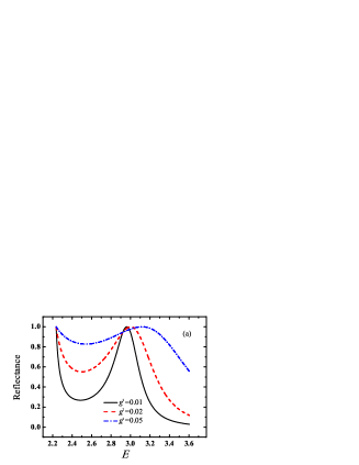
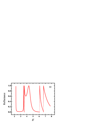
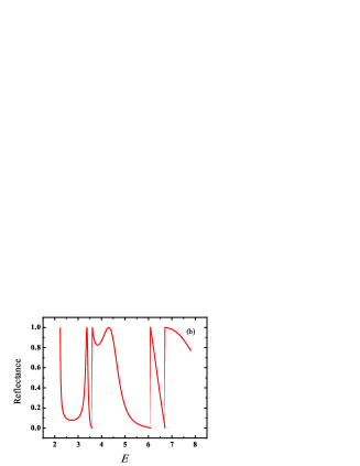
In Fig.4, we plot the reflectance as a function of the incident energy . A single photon confined in the TM11 mode (see Fig.4(a)) is indeed perfectly reflected by the TLS provided that is in the central domain of the range . However, the position of the total reflection experiences a blue shift to due to the renormalization, which becomes larger as the coupling strength increases. We note that total reflection also occurs when , which is referred to as the cut-off frequency resonance Huang-arxiv . When the incident energy is above , higher-order modes and the induced multi-channel interference effects must be taken into account. The reflectance with is plotted in Fig. 4(b). Although still determines the reflection peak, the maximum becomes smaller than unity, showing that single photons in the TM11 mode experience a finite loss due to the existence of the higher-order modes in a realistic waveguide. Actually, this loss is caused by the TLS mediating the resonant tunneling process between the TM11 mode and higher-order modes.
Controllable channel versus scattering-free channels. Now, we study the quantum interference among different TMmn modes. We assume that a single photon with energy incident from the negative z-direction is initially in this superposition state
| (7) |
where is the highest mode a photon with energy can reach, fixed by the condition . The complex coefficients (with ) represent the amplitudes in the th mode. Here, takes the discrete values illustrated in Fig.2, i.e., the crossing points between the horizontal line and the dispersion curves. With the scattering matrix elements in Eq.(5), the multi-channel outgoing state reads
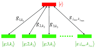
where , and are the right- and left-going creation operators respectively. For a photon with energy , the Hilbert space can be decomposed as the vector , which is proportional to the vector , and the complementary subspace, which is spanned by the vectors orthogonal to , i.e. Obviously, single photons incident in the states from one side of the rectangular waveguide will be completely transmitted to the other side. Thus, the vectors span a so-called scattering-free subspace to define the SFCs where the confined photons are decoupled from the TLS. This phenomenon is similar to the dark state of a three-level atom to support the electromagnetic induce transparency (EIT). Actually, the scattering-free state (with the photon energy ) can be understood as a multi-component dark state as illustrated in Fig.3. There exist the multi-channel transitions from to . The quantum interference among these channels results in the transparency of the TLS with respect to the incident photon. Thus, no reflected photon is observed.
The remaining vector orthogonal to the scattering-free subspace, defined by , is regarded as the controllable channel. In this channel, the TLS scatters the incident wave coming from the right into a superposition of the right- and left-going waves, which we denote as . From Eq.(LABEL:eq:phiout) the right- and left-going wave function is obtained as
| (9) | |||||
| (10) |
which is proportional to the incident wave function . The summation guarantees that there is no loss in the scattering process. Furthermore, in the weak coupling limit, one can observe a perfect reflection once the incident energy matches the renormalized energy of the TLS with the Lamb shift . As the cross section of the waveguide increases, the dimension of the scattering-free subspace increases for a given incident energy, but there still exists one controllable channel. Therefore, total reflection can always be observed as long as the incident photon is prepared in the controllable channel, regardless of how large the cross section is.
When the incident energy approaches any cut-off frequency , leads to , and . Consequently, single photons in the controllable channel can also be totally reflected when the energy of the photon matches the cut-off frequency of any TMmn mode. We refer to the total reflection due to as the cut-off frequency resonance Huang-arxiv .
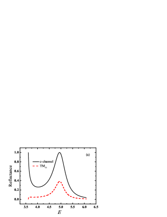
In Fig.5, the reflectance spectrum is numerically plotted for single photons incident in the controllable channel or in the TM11 mode. It can be found from Fig.5(a) that when higher-order modes are taken into account, it is impossible to find a constructive interference between the incoming wave and the spontaneous emission from the TLS in a given mode. However, single photons spontaneously emitted by the TLS are confined to the controllable channel. Consequently, spontaneous emission of the excited TLS can be exploited to control the coherent transport properties of single photons in the controllable channel, as shown in Fig.5(b). And the position of the total reflection is shifted from the atomic transition frequency due to the Lamb shift.
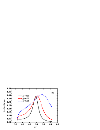
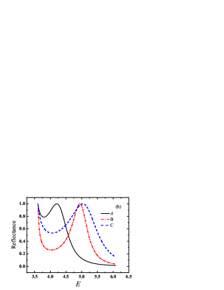
If the TLS-waveguide coupling is too strong, the resonance energy can only be determined by solving the transcendental equation , which may have more than one solutions, rather than the single solution in the weak coupling limit. Here, we consider the contribution of several low modes to the Lamb shift and a precise calculation shall be presented elsewhere. By including more modes, multi-peaks are observed in the reflectance spectrum as illustrated in Fig.6.
Conclusion. We have carried out a systematic study about the coherent scattering of single photons by a TLS in the realistic rectangular waveguide. Usually, the dipole oriented along the direction may scatter single photons guided in a TMmn mode into the others, but a photon with energy incident in the TM11mode can still be confined in TM11 after scattering. In this case, the TLS acts as an ideal quantum switch when the renormalized frequency is in the range . However, with higher energy , the single photons incident in TM11 resonantly tunnel to higher-order modes via the TLS.
For an artificial atom of transition frequency GHz key-23 to work as a quantum switch, the two lowest cut-off frequencies of the waveguide should satisfy , leading to the size of the cross section . Correspondingly, GHz, so that the scattering of microwave photons with energy GHz cannot be confined in the single mode TM11 and thus the multi-channel effects (loss and interference) are involved. If we want to control photons with higher energy, e.g. with energy about GHz, then we should use a waveguide of the size to work in the single mode region. Conversely, if , i.e. GHz, then the waveguide works in the multi-channel region, and in consequence we must utilize the controllable channel scheme to overcome the channel loss. The existence of the unique TLS-controllable channel and the complementary scattering-free channels guarantees the success in controlling single photons in a realistic waveguide with a finite cross section.
We are grateful to C. Y. Cai, T. Tian, J. F. Huang, Y. Li, P. Zhang and D. Z. Xu for helpful discussions. This work is supported by National Natural Science Foundation of China under Grants No.11121403, No.10935010, No.11222430, No.11074305, No. 11074261, No. 11074071 and National 973 program under Grants No. 2012CB922104, No. 2012CB922103. Hunan Provincial Natural Science Foundation of China (12JJ1002).
References
- (1) S.E. Harris and Y. Yamamoto, Phys. Rev. Lett. 81, 3611 (1998).
- (2) B.S. Ham and P.R. Hemmer, Phys. Rev. Lett. 84, 4080 (2000).
- (3) K.M. Birnbaum, A. Boca, R. Miller, A.D. Boozer, T.E. Northup, and H.J. Kimble, Nature (London) 436, 87 (2005).
- (4) M. Bajcsy, S. Hofferberth V. Balic T. Peyronel, M. Hafezi, A.S. Zibrov, V. Vuletic, and M. D. Lukin, Phys. Rev. Lett. 102, 203902 (2009).
- (5) J. T. Shen and S. Fan, Phys. Rev. Lett. 95, 213001 (2005), ibid. 98, 153003 (2007).
- (6) J. T. Shen and S. Fan, Phys. Rev. A 79, 023837 (2009), ibid. 79, 023838 (2009).
- (7) F. M. Hu, L. Zhou, T. Shi, and C. P. Sun, Phys. Rev. A 76, 013819 (2007).
- (8) L. Zhou, Z. R. Gong, Y.X. Liu, C.P. Sun, and F. Nori, Phys. Rev. Lett. 101, 100501 (2008).
- (9) Z. R. Gong, H. Ian, L. Zhou, and C.P. Sun, Phys. Rev. A 78, 053806 (2008).
- (10) T. Shi and C. P. Sun, Phys. Rev. B 79, 205111 (2009).
- (11) J. Q. Liao, J. F. Huang, Y. X. Liu, L.M. Kuang, and C. P. Sun, Phys. Rev. A 80, 014301 (2009).
- (12) X. Zang and C. Jiang, J. Phys. B: At. Mol. Opt. Phys. 43, 215501 (2010).
- (13) D.E. Chang, A.S. Søensen, E.A. Demler and M.D. Lukin, Nature Phys. 3, 807 (2007).
- (14) J. Hwang, M. Pototschnig, R. Lettow, G. Zumofen, A. Renn, S. Götzinger, V. Sandoghdar Nature 460, 76 (2009).
- (15) T. S. Tsoi and C. K. Law, Phys. Rev. A 78, 063832 (2008), ibid. 80, 033823 (2009).
- (16) T. Shi, S. H. Fan, and C.P. Sun, Phys. Rev. A 84, 063803 (2011).
- (17) S.C. Zhang, C. Liu, S.Y. Zhou, C.S. Chuu, M.M.T. Loy, and S.W. Du, Phys. Rev. Lett. 109, 263601 (2012).
- (18) Z. H. Wang, Y. Li, D.L. Zhou, C.P. Sun, and P. Zhang, Phys. Rev. A 86, 023824 (2012).
- (19) T. Aoki, A.S. Parkins, D.J. Alton, C.A. Regal, B. Dayan, E. Ostby, K.J. Vahala, and H. J. Kimble, Phys. Rev. Lett. 102, 083601 (2009).
- (20) L. Zhou, L.P. Yang, Y. Li, C.P. Sun, e-print arXiv:1303.3687.
- (21) J. F. Huang, T. Shi, C.P. Sun, and F. Nori, Phys. Rev. A 88, 013836 (2013).
- (22) U. Fano, Phys. Rev. 124, 1866 (1961).
- (23) O. Astafiev, A. M. Zagoskin, A. A. Abdumalikov Jr., Yu. A. Pashkin, T. Yamamoto, K. Inomata, Y. Nakamura, and J. S. Tsai, Science 327, 840 (2010).