The Formation of Condensation on Cherenkov Telescope Mirrors
Abstract
The mirrors of imaging atmospheric Cherenkov telescopes are different from those of conventional astronomical telescopes in several ways, not least in that they are exposed to the elements. One of the issues which may arise is condensation forming on the mirrors during observing under certain atmospheric conditions, which has important consequences for the operation of the telescopes. This contribution discusses why telescope mirrors suffer condensation and describes the atmospheric conditions and mirror designs which are likely to be problematic.
1 Introduction
Imaging atmospheric Cherenkov telescopes (IACTs) require mirrors that are robust, lightweight and have high reflectivity in the blue/UV region of the spectrum. Yet these mirrors must also be inexpensive and capable of rapid manufacture due to the large mirror areas required. This unusual combination of properties has led to many innovative approaches to mirror production, including the use of composite structures and materials such as fibreglass in addition to the more traditional solid glass mirrors (see, e.g. [9] for a summary). Recently, the requirement for a robust surface that is highly reflective in the blue region of the electromagnetic spectrum and also has low reflectivity in the red (in order to reduce the effects of sky background) has led to research into dielectric-coated materials, with layers of e.g. SiO2 and Ta2O5 [10]. These can be tuned to provide the required performance, and have the further advantage of being particularly resistant to abrasion.
No mirror type is without problems; in particular, although providing excellent optical quality, solid glass mirrors are heavy and time-consuming to produce. Composite mirrors, usually consisting of an aluminium honeycomb substrate bonded to a pre-formed reflective surface, are particularly useful in this respect, being generallly % lighter than solid glass mirrors for a given area. However, anecdotal evidence from current and previous IACT experiments is that composite mirrors are particularly prone to condensation on their surface during observations (see, e.g. [5]). This causes absorption and scattering of the Cherenkov light and results in a considerable drop in the telescopes’ count rate. We report here the results of a study of this phenomenon, undertaken in the light of the design of mirrors for the forthcoming Cherenkov Telescope Array (CTA).
2 The Formation of Condensation
The likelihood of condensation forming on a mirror surface depends on the ambient temperature, the temperature of the surface and the relative humidity. For detailed studies of the formation of condensation, see [2, 12]; the following is a basic account.
The temperature at which air becomes saturated, and will therefore form condensation, is the dew point, . This can be determined from the values of the ambient temperature, and the relative humidity by employing a variant of the Magnus-Tetens formula [1]:
| (1) |
where:
| (2) |
with the Magnus coefficients defined as = 17.27 and . As soon as the mirror surface temperature is equal to the dew point temperature, moist, warmer air in contact with the mirror surface will cool to the dew point and form condensation.
In sub-zero temperatures it is possible for frost to form on a surface without condensation forming first. In this case, the stronger bonding in solid water raises the frost point above the dew point. Fitting to data from dew point/frost point conversion tables [6], we find that the frost point is related to as follows:
| (3) |
with and . This equation is only valid when .
3 The Cooling of Surfaces
In order to model the cooling on any surface, conduction, convection and radiation must be taken into account.
3.1 Conduction
It is likely that the reflective, front surface of a mirror will possess a lower surface temperature than the rear of the mirror, due to radiative cooling of the reflective surface when it is pointed at the night sky, and therefore a temperature gradient will exist from the rear to the front of the mirror. The rate of thermal energy transfer in Watts can be expressed as:
| (4) |
where is the thermal conductivity of the mirror in and its thickness, is the area of the material in m2 and is the temperature difference between the front and the rear of the mirror.
3.2 Convection
Convective heat transfer is likely via forced rather than natural convection, as winds will flow over the mirror surface. The rate of heat transfer bewteen the mirror surface and the ambient air is given by:
| (5) |
where is the convective heat transfer coefficient in and in this case is the difference between the ambient air temperature and that of the mirror surface. In this study, was taken to be where is the wind speed passing across a flat surface in [7].
3.3 Radiation
The most important thermal process for the purpose of this study is radiative heat transfer. During observations, IACT mirrors are pointed towards the clear night sky, which is partially transparent in the 8 to 14 m waveband [3]. The sky therefore has an effective temperature considerably lower than the ambient temperature, and the mirrors will, as far as possible, equalise with this low temperature by the loss of thermal radiation, particularly in the 8 to 14 m waveband. It has been shown that a typical black body surface will drop to temperatures of 18 to 33 below the ambient temperature by radiative cooling alone [8]. However, any interfering medium, particularly a high concentration of water vapour, will inhibit the transfer of radiation. Radiation reflects off the interfering medium and produces a counteracting ‘down-welling’ radiation. This is related to the emissivity of the night sky between 8 and 14 m, , which in turn is directly related to the relative humidity of the ambient air and can be expressed as [11]:
| (6) |
where is given by [4]:
| (7) |
and the sky radiance, , of a clear sky in Wm-2 is:
| (8) |
where is the Stefan-Boltzmann constant. Similarly, incoming radiation from surrounding objects obscuring the night sky will have an effect, but this is disregarded here as it is assumed all mirrors will observe a completely unobscured night sky. This is a limitation of the present study, since this will not be true for all mirrors on a telescope, but nonetheless the majority should be unobscured. In this case:
| (9) |
where:
| (10) |
and is the emissivity of the mirror in the 8 to 14 m waveband.
3.4 Net Effect of Thermal Processes
Combining conduction, convection and radiative heat transfer, the net loss of thermal energy, , from the front surface of a mirror of thickness exposed to a clear night sky is given by:
| (11) |
where and are the temperatures of the back and front of the mirrors in degrees Kelvin.
4 Outside Testing of Mirrors
The mirrors used in the tests described here are listed in Table 1. These mirrors were tested by placing them outside at two locations in the UK, Durham (in the North of England) and Chelmsford (in the South) on nights which were as clear and calm as possible during December 2011 - March 2012. The mirrors were placed facing directly upwards and their surface temperatures were measured using K-type thermocouples attached to the mirrors’ surfaces. These temperatures were recorded using simple remote data-loggers and the mirrors were also checked visually for the formation of condensation and/or frost during the tests.
| Mirror | Type | Materials | Surface | Size (m) | Thickness (m) |
|---|---|---|---|---|---|
| A36 | Solid | Soda lime float glass | Al/SiO2 | 0.6 | 0.02 |
| T191 | Solid | Kavalier SIMAX glass | Al/SiO2 | 0.6 | 0.015 |
| T6086 | Solid | Kavalier SIMAX glass | Dielectric, SiO2 and Ta2O5 | 0.6 | 0.015 |
| T1010 | Solid | Kavalier SIMAX glass | Al/SiO2 + hydrophobic coating | 0.6 | 0.015 |
| K1 | Composite | Glass + open metal substrate | Al/SiO2 | 0.4 | 0.08 |
| D1 | Composite | Alanod + Al honeycomb | Al + proprietary coating | 0.48 | 0.03 |
| M1 | Composite | Al surface + honeycomb | Al/SiO2 | 0.17 | 0.025 |
| M2 | Composite | Glass + Al honeycomb | Al/SiO2 | 0.2 | 0.024 |
| Date | A36 | T191 | T6086 | T1010 | K1 | D1 | M1 | M2 |
|---|---|---|---|---|---|---|---|---|
| 18/12/11 | F | F | F | F | - | - | - | - |
| 22/12/11 | C | - | - | - | - | |||
| 28/12/11 | - | - | - | - | ||||
| 02/01/12 | - | - | - | - | ||||
| 05/01/12 | F | - | - | - | - | |||
| 10/01/12 | C | - | - | - | - | |||
| 12/01/12 | C | - | - | - | - | |||
| 13/01/12 | F | - | - | - | - | |||
| 16/01/12 | F | - | - | - | - | |||
| 23/01/12 | C | - | - | - | - | |||
| 02/02/12 | - | F | - | - | ||||
| 05/02/12 | - | F | C | C | - | - | ||
| 07/02/12 | - | C | - | - | ||||
| 08/02/12 | - | F | - | |||||
| 15/02/12 | - | C | - | |||||
| 16/02/12 | - | C | - | |||||
| 24/02/12 | - | - | ||||||
| 25/02/12 | - | C | C | - | ||||
| 28/02/12 | - | C | - | - | ||||
| 29/02/12 | - | C | - | - | ||||
| 01/03/12 | - | C | - | |||||
| 02/03/12 | - | - | C | - | ||||
| 05/03/12 | - | - | F | - | ||||
| 07/03/12 | - | - | - | - | ||||
| 10/03/12 | - | - | C | - |
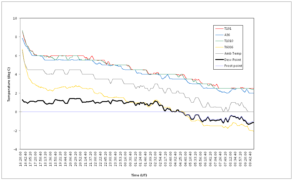
Table 2 shows the results of testing the mirrors for condensation and the formation of frost on their surfaces (note that not all mirrors were available throughout the full study). These results show that the composite mirrors do show a slightly greater tendency to suffer condensation or frost than the solid glass mirrors, but this brief study suggests it is not a major effect. A much greater tendency to suffer condensation is observed in the case of the solid glass mirrors with the dielectric coating. The reason for these results can be seen in Figure 1; the dielectric-coated mirror cools much more rapidly than the other glass mirrors and is therefore more likely to reach the dew point than the other mirrors on any given night.
5 Discussion
The outside mirror testing showed the initially surprising result that the solid glass dielectric-coated mirrors showed the greatest tendency of any of the mirror types to suffer condensation or frost, including the composite mirror types. It might be expected that the composite mirror types would suffer more from condensation due to their relatively low thermal conductivity , which has an effect on the net loss of thermal energy via conduction, as shown in Equation 4. However, another factor is clearly having a much greater effect, and this is the emissivity of the mirrors, , which is important for the radiative cooling of the mirrors, as shown in Equation 10.
Measurements of the emissivity of three of the mirrors, A36, T6086 and D1, showed that the emissivity of A36 and D1, both of which have aluminium front surfaces, is between 8 and 14 m. However, the emissivity of T6086, the dielectric mirror, is over the same waveband. This will result in rapid cooling of the mirrors and hence the formation of condensation or frost, as observed in our trials.
6 Conclusions
We have shown that emissivity between 8 and 14 m is the most important factor controlling the formation of condensation on Cherenkov telescope mirrors, not the method of construction. This is a particular issue for mirrors with dielectric coatings which have been tuned to provide low reflectivity in the red region of the spectrum to reduce the effects of the night sky background. The corollary of this cut-off beyond nm is high emissivity in the mid-infrared, which causes the mirrors to cool quickly. It may be possible to improve these coatings in order to reduce this effect.
The equations which describe surface cooling can be used to predict the surface temperatures of mirrors, provided that the basic mirror and meteorological data are available, and comparison of predicted mirror temperature with the dew point makes it possible to estimate when mirrors of a given type will suffer condensation at a particular candidate telescope site. This is an important consideration for the design of Cherenkov telescope mirrors and the choice of telescope site and will be the subject of further study.
Acknowledgment:We would like to acknowledge colleagues in CTA for the provision of mirror samples, and Prof. David Wood of the School of Engineering and Computer Sciences at Durham University for help with emissivity measurements. We gratefully acknowledge support from the agencies and organizations listed in this page: http://www.cta-observatory.org/?q=node/22
References
- [1] A. Barenburg, Psychrometry and Psychrometric Charts (3rd Edition), Cape Town:Cape and Transvaal Printers Ltd., 1974
- [2] R. Barry and R. Chorley, Atmosphere, Weather and Climate (5th Edition), London: Methuen, 1987
- [3] P. Berdahl and R. Fromberg, Solar Energy 29 (1982) 299-314
- [4] D. Bolton, Monthly Weather Review, 108 (1980) 1046-1053
- [5] K. Brazier at al., Experimental Astronomy, 1 (1989) 77-99
- [6] See, for example, www.bry-air.com/dew-point-frost-point-conversion-tables.html (accessed May 2013)
- [7] J. Duffie, Solar Energy Thermal Processes, New York: John Wiley & Sons Inc. (1974)
- [8] T. Eriksson and C. Grandqvist, Applied Optics 21 (1982) 4381-4388
- [9] A. Förster et al., Proc. 32nd Int. Cosmic Ray Conf. 9 (2011) 130-133
- [10] A. Förster et al., Contribution no. 755, these proceedings
- [11] S. Idso, Water Resources Research 17 (1981) 295-304
- [12] P. Marsh, Thermal Insulation and Condensation, Lancaster: The Construction Press (1979)