Origin of Anomalous Water Permeation through Graphene Oxide Membrane
Abstract
Water inside the low dimensional carbon structures has been considered seriously owing to fundamental interest in its flow and structures as well as its practical impact. Recently, the anomalous perfect penetration of water through graphene oxide membrane was demonstrated although the membrane was impenetrable for other liquids and even gases. The unusual auxetic behavior of graphene oxide in the presence of water was also reported. Here, based on first-principles calculations, we establish atomistic models for hybrid systems composed of water and graphene oxides revealing the anomalous water behavior inside the stacked graphene oxides. We show that formation of hexagonal ice bilayer in between the flakes as well as melting transition of ice at the edges of flakes are crucial to realize the perfect water permeation across the whole stacked structures. The distance between adjacent layers that can be controlled either by oxygen reduction process or pressure is shown to determine the water flow thus highlighting a unique water dynamics in randomly connected two-dimensional spaces.
For the last few decades, several studies of the water inside porous carbons, graphite and graphene oxide, and carbon nanotubes have provide a plenty of intriguing experimental results. 1 ; 2 ; 3 ; 4 ; 5 ; 6 ; 7 ; 8 ; 9 ; 10 ; 11 ; 12 Formation of various kinds of ice in different environment has also been important subject on the edge of current physics and chemistry. 13 ; 14 ; 15 ; 16 ; 17 Very recently, the anomalous perfect permeability of graphene oxide membrane for water was demonstrated although other liquids and even gases cannot penetrate the membrane. 9 A sudden volume expansion with increasing pressure, i.e., auxetic material behavior was also reported for graphene oxide in the presence of water. 10 In the work of Nair et al (Ref. 9), the permeation of water through graphene oxide membrane has been explained in terms of anisotropic migrations of water clusters following unoxidized areas within graphene oxide sheets 18 ; 19 ; 20 (see Fig. 1). Brownian (isotropic) motion of the molecules of simple gases (He, Ar, N2, H2) does not lead to any noticeable permeation. 9 These observations probably force us to assume some kind of collective motion for the anomalous water permeation such as a formation of ice-like structures. Interlayer distance in graphene oxide membranes is another important factor to control the water flow since the decrease of interlayer distance after reduction of graphene oxide makes the membrane impenetrable even for water. 9
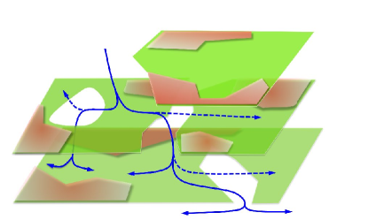
To realize liquid or gases permeation throughout randomly stacked two-dimensional flakes, three important necessary conditions should be fulfilled. Here we suppose that the single layer flake itself is impenetrable for any liquid or gas. First, the capillaries in between two-dimensional flakes are required. If small molecules propagate freely in the interlayer space between stacked two dimensional materials, they can hardly flow to any specific point, e.g., to the edges of flakes. Thus, the lateral confinements in a reduced area are particularly helpful to quench the random motion of particles. In graphene oxide membrane, the unoxidized part plays as the capillary 9 ; 18 ; 19 ; 20 (Fig. 1). Second, anisotropic energy barriers for migration of liquids or gases in the capillary are necessary. Even though some space in between the layers is prepared through the formation of capillaries, the isotropic molecular motion inside them will result in a low probability of directional flow from one capillary to the other within the interlayer space. Third, assuming that they all manage to reach the edge of the flakes, those free molecules will continue to move or wandering around in the same interlayer space rather than jump to another interlayer space, thus impossible to penetrate across the whole membrane (Fig. 1). So, the energy gain at the passing of molecules from one interlayer space to the other is required for a liquid to flow across the stacked flakes. For the case of water, according to the recent experiments, 9 it seems to be a collective water flow from one interlayer space to the other but its molecular mechanisms and the strong dependence of the effect on the interlayer distance have not been clarified yet.
A systematic investigation of interaction between graphene oxide and water under pressure demonstrates a crucial role of the interlayer distances. 10 ; 11 ; 12 Anomalous negative volumetric compressibility in the system has been observed when the interlayer distance in graphene oxide was about 9 Å. 10 Deviation from this optimal distance makes the system behave as normal materials under pressure. 10 Such a strong dependence on the interlayer distance distinguishes the confined water characteristics from those in other carbon nanomaterials. Another key point in this two-dimensional system is the possibility of formation of a highly symmetric ice monolayer (see for illustration Fig. 2a) over a perfect graphene sheet. 21 Observation of structural anomalies in graphene/alcohols mixes 22 ; 23 and its absence in graphene/acetone 24 mix deserve further investigation on their atomistic structures and flow dynamics. Despite of many experimental and theoretical works on hybrid systems composed of graphene (oxides) and water, a comprehensive picture which might explain the relationship between the interlayer distance and structural properties of hexagonal ice formed between graphene layers is still lacking, which is also important to understand migration of the ice layers across multiply stacked graphene (oxide) layers.
All calculations were performed based on first-principles pseudopotential calculation methods 25 with the generalized gradient approximation and with spin-polarization. 26 The wavefunctions were expanded with a double- plus polarization basis of localized orbitals for carbon and oxygen, and a double- basis for hydrogen. Optimization of the force and total energy was performed within 0.04 eV/Å and 1 meV, respectively. For the modeling of graphene layers we used a rectangular-like unit cell with 20 carbon atoms in each carbon layer and four water molecules in each layer of ice with periodic boundary conditions (see Fig. 2). For the checking the role of the supercell size for the energy costs of water migration over hydrophilic edges (Fig. 3) we multiply twice the supercell size in direction normal to the breaks of graphene sheets and find that the energetic hierarchies do not change. An energy mesh cut-off of 300 Ry and a k-point mesh of 884 are used for our large supercell geometries. We note that our method and modeling geometries were successfully used for description of graphene-water interfaces 27 ; 28 and modeling of graphene oxide atomic structure. 29 ; 30 For the additional check the calculations of the values of energy barriers with employment of LDA functionals 31 have been employed. Binding energy of the water molecule was calculated as , where and are the energy and number of water molecule in the empty box (in gaseous phase) respectively, the total energy of graphene or graphite with the hexagonal ice structure between carbon layers, and the total energy of the carbon structure before insert of ice layers. Binding energy between graphene and ice monolayer is , where is the total energy of freestanding hexagonal ice layer.
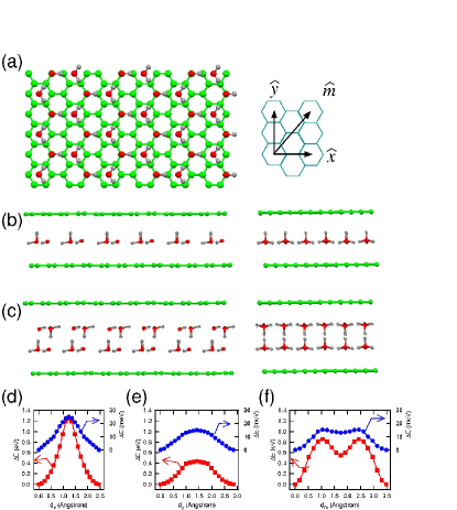
First, we examine the case of ice monolayer over single-layer graphene (Figs. 2a and 2b). The calculated binding energies between water molecules in this structure are quite large ( eV/H2O) reflecting very strong hydrogen bonds (the total cohesive energy of the hydrogen bonds defined as the difference between the formation energies of water in the liquid and gaseous phases is as high as 0.46 eV), 32 in contrast to the binding energy between graphene and ice monolayer ( meV/H2O). Note that the latter value is still much larger than typical van der Waals energies, which are usually less than 10 meV, 33 due to polarity of water molecule. The results obtained demonstrate that graphene is the matrix for the formation of layered hexagonal ice structure (Fig. 2a). The hexagonal structure of graphene scaffold provides an initial pattern for the ordering of water molecules in an energetically favorable structure with hexagonal symmetry and the axes coinciding with the crystallographic axes of graphene. Combination of weak ice-graphene interactions and strong internal interactions within the ice layer enables the whole ice layer slide over graphene, as was suggested in Ref. 9.
We also examined the formation of this water monolayer between the two graphene layers, between every second layers in graphite, and between every layer in graphite, as well as various types of their stacking orders different from ordinary Bernal type one. The interlayer distance between graphene layers separated by the ice monolayer is about 6Å (5.74 5.87 Å), the value discussed in the literature10 as a minimal distance in graphene oxide/water systems. This value is very close to the interlayer distance in reduced graphene oxide impenetrable for water. 9 The presence of carbon layer from the other side of ice monolayer has negligible contributions (about meV/H2O for different types of stacking) in changing the binding energy between water molecules in ice and between ice and graphene. To model the motion of water monolayer between graphene planes we moved the monolayer along different directions and calculated the energy relief (Figs. 2d-2f). Energy barriers were calculated as meV/H2O along zigzag direction, meV/H2O along armchair direction, and meV/H2O along intermediate direction (errorbars corresponds to various types of stacking orders). Values of these energy barriers calculated within LDA are 4 meV higher. Thus, the motion of ice monolayer in between graphene layers can be concluded as isotropic.
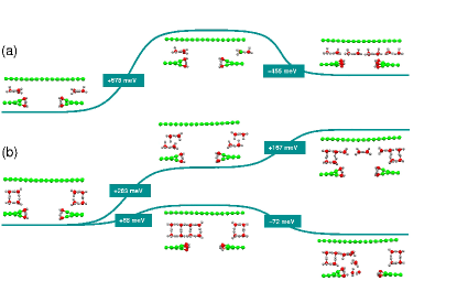
Let us have a look now at the interaction between water monolayer and the edge of graphene flake. To simulate this, we consider a hybrid system composed of water monolayer and graphene double layer; the water monolayer is sandwiched between a perfect top graphene layer and an imperfect bottom graphene layer with a hole formed by eliminating several rows of carbon atoms along armchair direction. The edges in the bottom layer were passivated by hydroxyl groups (Fig. 3a) as a proper way to model hydrophilic edges of graphene oxide sheets. 34 We calculate the energy costs for the migration of water monolayer through the edge, similar to the way how it was done for the migration relief across the layer spaces in the bulk. The computational results (Fig. 3a) show that, due to interactions of water molecules with hydroxyl groups, the ice structure was strongly distorted and the height of the barriers was increased in the two orders of magnitude in comparison with the bulk case. This means that, when reaching the edge, it is much more energetically favorable for the water monolayer to continue to slide along the carbon sheet than to pass through the hole within graphene oxide flakes. Since the distance between graphene layers with ice mono-layer (Fig. 2b) corresponds to the typical one for reduced graphene oxide we have explained in this way why this material is impenetrable for water, in agreement with the experimental observations. 9
For larger interlayer distances, formation of water bilayer between graphene oxide sheets is possible. So, we switch to the modeling of this case. We have performed the calculations of different types of stacking of carbon sheets in double layer graphene and graphite and various mutual orientations of the ice layers and found that the structures shown in Fig. 2c are the most energetically favorable for ice structures between graphene layers as well as between layers in graphite. The binding energy between water molecules in the ice bilayer was calculated as eV/H2O, that is, a hexagonal ice bilayer is more energetically favorable than monolayer due to formation of additional hydrogen bond per each water molecule with a help of the enough space for its formation. Similar to the case of water monolayer, the axes of the formed bilayer hexagonal ice coincide with the crystallographic axes of graphene. The equilibrium distance between graphene layers separated by the ice bilayer is within the range Å for different types of stacking corresponding to the range for the interlayer distances in stacked graphene oxide allowing water permeation (Å). 9 ; 13 Calculations of the energy barriers for the shift of one of ice layer over another (see Figs. 2d-2f) demonstrate much higher values of the migration barriers than for ice monolayer case considered before and, more importantly and less trivial, a significant anisotropy of the migration energy relief. Calculations of the same barriers within LDA leads increasing of the values about 60 meV that corresponding with overestimation of bonds strengths within this method. We find that the migration of one ice layer along zigzag direction is the most favorable. The cause of colossal energy barriers for the sliding in armchair direction is the passing of hydrogen atoms of water molecules from one layer in the vicinity (about 0.1Å) of the hydrogen atoms from the other layer (Fig. 2c). For the case of migration along zigzag direction, the distance between hydrogen atoms is the largest and therefore the energy barriers are minimal. The energy cost for this case mainly originates from the hydrogen bonds breaking between ice layers. Considering both the energy required for the water evaporation at the room temperature (0.46 eV/H2O) 32 and additional pressure induced by capillaries in the systems, we expect that the barrier can be easily overcome in the experimental conditions. 9 ; 10 Thus, we can conclude here that the interlayer distance in the stacked graphene oxide flakes is quite optimal allowing formation of ice bilayer in the interlayer space and its anisotropic water flowing, otherwise only random Brownian movements of water occur.
We have considered also energetics of motion of the second ice layer over the edge of graphene oxide flake, similar to the case of ice monolayer discussed above. It turned out that the migration of the second ice layer through the edge along zigzag direction (Fig. 3b) is energetically more favorable (by 100 meV/H2O) than its further gliding along the first ice layer in the same plane. The reason is that the distortions of ice structure due to interaction with hydroxyl groups associated with the edge decrease the interlayer interaction in ice. Further, alternative processes are either migration of the ice layer in the plane or a shift of water molecules from top layer to the bottom one with further destruction (melting) of ice (Fig. 3b). Our calculations show that the last process is the most energetically favorable. Thus, edges of graphene oxide passivated by hydrophilic groups stimulate a destruction of ice bilayer (but not monolayer) with penetration of water molecules to the next void where they form another ice bilayer. This is the model of the process shown schematically in Fig. 1. We believe therefore that the formation of ice bilayer in unreduced graphene oxide is the crucial element in anomalous penetration of water through graphene oxide paper. 9
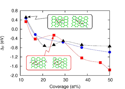
The anisotropy of the migration of water in the case of ice bilayer can explain why water penetrates throughout graphene oxide multilayers only with interlayer distances Å. 9 We have to consider, as the next step, the role of capillaries formed by reduced graphene regions in unreduced graphene oxide. We have made a series of calculations for coexisting reduced and unreduced areas. One can easily see that in the typical graphene oxides (about 50% of carbon atoms are connected with oxygen or hydroxyl groups) capillaries from unoxidezed area can connect each other across all stacking layers regardless of random oxidation area distributions in each layer. Next, we have model the step-by-step oxidation of graphene sheet with formation of graphene oxide for the various coverage of hydroxyl and epoxy groups. We have started with the pair of hydroxyl groups (as more stable) and added the next pair of hydroxyl groups or epoxy groups in according to the previously discussed principles of graphene oxide functionalization 29 ; 30 with the tendency to form oxidized patterns along zigzag or armchair directions (Fig. 4). The computational results demonstrate that for the small amount of epoxy and hydroxyl groups (below 15% that corresponds to the case of reduced graphene oxide) the formation of stripes along armchair direction is more energetically favorable. With the increase of the number of functional groups, however, the preferable direction of stripe-like oxidized areas switches to zigzag direction (Fig. 4). The continuous web of capillaries oriented along zig-zag direction plays probably a crucial role in water permeation. Independence of the favorability of patterns oriented along zig-zag direction from the ratio of epoxy and hydroxyl groups suggest for the preference of these capillaries in all types of unreduced graphene oxides with different exact atomic structures.
To be complete, we have performed the same modeling for the case of ice trilayer between graphene sheets. The calculated equilibrium distance between graphene layers is about Å for different types of graphene stacking. Following the same calculation procedures for ice mono- and bi-layer in between graphene layers, we find that the ice trilayer energetics are quite similar to those of monolayer. These calculations therefore can explain the reason why the auxetic behavior of graphene oxide realizes in the very specific condition 10 because the only optimal interlayer distance for ice bilayer formations can allow water filling through graphene oxide against the pressure. All considerations hitherto thus support that the formation ice bilayer inside graphene oxide membranes and their melting behaviors owing to their optimal interlayer distance are the crucial reasons why they allow perfect permeation for waters not for others 9 and why they exhibit the auxetic behaviors of graphene oxide inside waters. 10
Acknowledgements.
M. I. K. acknowledges support from FOM (the Netherlands). Y.-W. S. was supported by the NRF of Korea grant funded by the MEST (CASE, 2011-0031640 and QMMRC, No. R11-2008-053-01002-0). Computations were supported by the CAC of KIAS.References
- (1) M. D. Fayer, Chem. Res. 45, 3-14 (2012).
- (2) T. Iiyama, K. Nishikawa, T. Otowa, K. Kaneko, J. Phys. Chem. 99, 10075-10076 (1995).
- (3) H. J. Knox, B. Kaur, G. R. Millward, J. Chrom. A 352, 3-25 (1986).
- (4) J. C. Rassaiah, S. Garde, G. Hummer, Annu. Rev. Phys. Chem. 59, 713-740 (2008).
- (5) J. Köfinger, G. Hummer, C. Delago, Proc. Natl. Acad. Sci. U.S.A. 105, 13218-13222 (2008).
- (6) M. Majumder, N. Chorpa, R. Andrews, B. J. Hinds, Nature 438, 44 (2005).
- (7) X. Qin, Q. Yuan, Y. Zhao, S. Xie, Z. Liu, Nano Lett. 11, 2173-2177 (2011).
- (8) N. Severin, P. Lange, I. M. Sokolov, J. P. Rabe, Nano Lett. 12, 774-779 (2012).
- (9) R. R. Nair, H. A. Wu, P. N. Jayaram, I. V. Grigorieva, A. K. Geim, Science 335, 442-444 (2012).
- (10) A. V. Talyzin et al., Angew. Chem. Int. Ed. 47, 8268-8271 (2008).
- (11) A. V. Talyzin et al., Carbon 49, 1894-1899 (2011).
- (12) S. M. Luzan, A. V. Talyzin, J. Phys. Chem. C 115, 24611-24614 (2011).
- (13) R. Zangi, A. E. Mark, Phys. Rev. Lett. 91, 025502 (2003).
- (14) N. Giovambattista, P. J. Rossky, P. G. Debendetti, Phys. Rev. Lett. 102, 050603 (2009).
- (15) H. Forbert, M. Masia, A. Kaczmarek-Kedziera, N. N. Nair, D. Marx, J. Am. Chem. Soc. 133, 4062-4072 (2011)
- (16) Y. Zhai, A. Laio, E. Tosatti, X.-G. Gong, J. Am. Chem. Soc. 133, 2535-2540 (2011).
- (17) V. J. Schaefer, Chem. Rev. 44, 291 (1949).
- (18) G. Eda, M. Chhowalla, Adv. Mater. 22, 2392-2415 (2010).
- (19) D. Pacilé et al., Carbon 49, 966-972 (2011).
- (20) N. R. Wilson et al., ACS Nano 3, 2547-2556 (2009).
- (21) G. A. Kimmel et al., J. Am. Chem. Soc. 131, 12838 (2009).
- (22) S. J. You et al., J. Phys. Chem. C 117, 1963-1968 (2013).
- (23) S. J. You, B. Sundqvist, A. V. Talyzin, ACS Nano 7, 1395-1399 (2013).
- (24) A. V. Talyzin, S. M. Luzan, J. Phys. Chem. C 114, 7004-7006 (2010).
- (25) E. Artacho et al., J. Phys.: Condens. Matter 20, 064208 (2008).
- (26) J. P. Perdew, K. Burke, M. Ernzerhof, Phys. Rev. Lett. 77, 3865-3868 (1996).
- (27) T. O. Wehling, A. I. Lichtenstein, M. I. Katsnelson, Appl. Phys. Lett. 93, 202110 (2008).
- (28) I. Hamada, Phys. Rev. B 86, 195436 (2012).
- (29) D. W. Boukhvalov, M. I. Katsnelson, J. Am. Chem. Soc. 130, 10697-10705 (2008).
- (30) L. Wang et al. Phys. Rev. B 82, 161406 (2010).
- (31) J. P. Perdew, A. Zunger, Phys. Rev. B 23, 5048-5079 (1981).
- (32) D. R. Lide, ed. CRC Handbook of Chemistry and Physics (86th ed.), Boca Raton (FL): CRC Press (1992).
- (33) I. Israelachvili, Intermolecular and Surface Forces, 2nd edition, Academic Press (1992).
- (34) D. R. Dreyer, S. Park, C. W. Bielawski, R. S. Ruoff, Chem. Soc. Rev. 39, 228 (2010).