Experimental Detection of Quantum Channels
Abstract
We demonstrate experimentally the possibility of efficiently detecting properties of quantum channels and quantum gates. The optimal detection scheme is first achieved for non entanglement breaking channels of the depolarizing form and is based on the generation and detection of polarized entangled photons. We then demonstrate channel detection for non separable maps by considering the CNOT gate and employing two-photon hyperentangled states.
Introduction — The experimental realization of a quantum channel is unavoidably affected by noise. One possible way to check how well this has been performed is to make a full tomography of the process. This nevertheless is known to be very expensive in terms of number of measurements to be performed NC . In many practical situations, however, one is only interested in some specific properties of the experimental channel, e.g. whether it has some entangling power, in order for the channel to be useful for a specific task, as e.g. quantum communication.
In this work we address this problem experimentally, following the method of quantum channel detection recently proposed in Refs. ns1 ; ns2 . The method allows us to detect properties of quantum channels when some a priori information about the form of the channel is available. Besides being less informative than full process tomography, the method gives the advantage to single out the property of interest with a much smaller experimental effort than in the full tomography case.
The method relies on the concept of witness operators horo-ter and the Choi-Jamiolkowski isomorphism jam . We briefly remind both of them. A state is entangled if and only if there exists a hermitian operator such that and for all separable states; such an operator is called an entanglement witness. The Choi-Jamiolkowski isomorphism gives a one-to-one correspondence between completely positive (CP) and trace-preserving (TP) maps acting on (the set of density operators on , with finite dimension ) and bipartite density operators on (named Choi states). The isomorphism can be stated as
| (1) |
where is the identity map, and is the maximally entangled state with respect to the bipartite space , i.e. . The above isomorphism can be exploited to link convex sets of quantum channels to particular sets of quantum states. In the following the proposed method will be applied to the convex sets of either entanglement breaking (EB) channels and separable channels.
1-qubit EB channels: Theory — A channel is EB if and only if its Choi state is separable EB . Therefore, the detection of entanglement of in the doubled system by using a witness operator suitable for allows us to prove that the implemented quantum channel was not EB.
We will show the method for the depolarizing channel acting on one qubit, defined as
| (2) |
where is the identity operator, are the three Pauli operators respectively, and (with ), while for . Such a channel is known to be EB only for . Denoting the maximally entangled state of two qubits as , the corresponding Choi state is given by
| (3) |
which leads ent-wit ; jmo to a suitable detection operator of the form ent-wit ; ns2
| (4) |
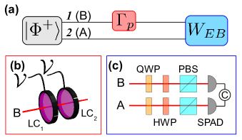
The detection scheme is depicted in Fig. 1 (a): we prepare the two-qubit system in the maximally entangled state , we then let the depolarizing channel act on qubit 1, and we finally measure the operator acting on both qubits at the end. If , then we are guaranteed that the depolarizing channel is not EB. Notice that the theoretical calculated expectation value for the ideal Choi state is , that guarantees the detection of all non EB depolarizing channels because it gives a negative expectation value whenever .
Notice that from the measured we can establish a lower bound ns2 on the theoretical quantity introduced in giova , which represents the minimal amount of noise we need to add to via a classical stochastic process in order to make the resulting map EB. Such a bound is given by
| (5) |
1-qubit EB Channels: Experiment — The two-photon states used in this work were produced by a spontaneous parametric down conversion (SPDC) source operating on the double excitation (back and forth) of a type I, -long BBO crystal, that, depending on the performed experiment, allows to generate either a polarization entangled state PRA70rome , or a path-polarization hyperentangled state PRA72rome of two photons emitted over either two or four spatial modes (see Supplementary Information (SI) for major details).
For this experiment, the 2-photon polarization entangled state generated over two spatial modes (Fig. 1 (a)) was: , where () stands for the horizontal (vertical) polarization of photon (Alice’s) or (Bob’s).
We simulated a 1-qubit depolarizing channel, Eq. (2), acting on Bob’s photon by inserting two liquid crystal retarders (LC1 and LC2) on the path of photon , one having its fast axis horizontal and the other oriented at 45∘ with respect to the horizontal PRL107romepavia (Fig. 1 (b)). Depending on the applied voltage , it is possible to change the retardation between ordinary and extraordinary polarized radiation. More precisely, by applying either or to a LC, it can be made to act as either a full- or a half-wave plate, respectively. Thus, by varying independently the voltage applied to LC1 and LC2 for different time intervals, we could apply the four Pauli operators to photon with different values of the weight (see SI).
To measure the witness given by Eq. (4) as a function of the noise level, varying between the values 0 and 1, we needed to evaluate , and for different values of . This was done, for each choice of , by measuring the coincidences between photons and in 8 different settings PRL91romepavia of the polarization analysis set-up which consisted of a quarter-wave plate (QWP), a half-wave plate (HWP), a polarizing beam-splitter (PBS) and a single-photon avalanche photodiode (SPAD) (Fig. 1 (c)).
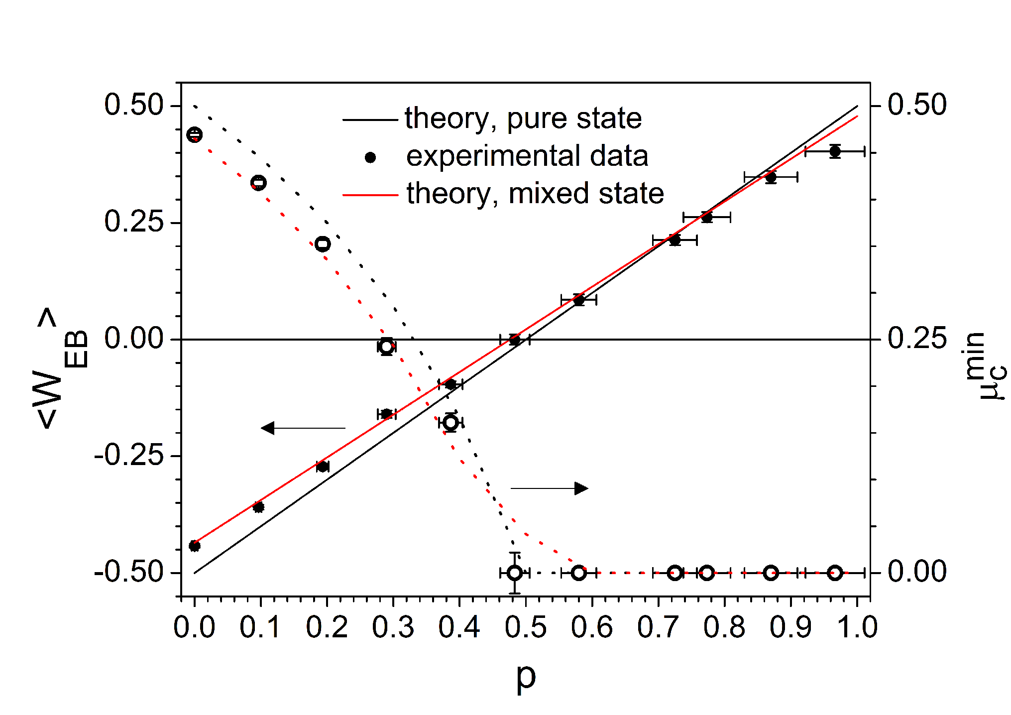
The witness we obtained is shown in Fig. 2, together with the theoretical behaviour for a perfectly pure state and the actual one used in the experiment. To compare our results with the theory, we need in fact to take into account the imperfection of the experimentally simulated Choi state. Indeed, the two-photon state produced by the SPDC source corresponds to only up to a finite fidelity (measured by performing a two-photon quantum state tomography for ). Replacing by in Eq. (3), we can thus write the experimental Choi state as:
| (6) | |||||
The error bars on are obtained by propagating the Poissonian uncertainties associated with the coincidence counts and the error bars on are estimated by considering the finite response time of the LC.
Let us notice that we indeed obtain the entanglement breaking property of the channel for a value of up to around 0.5 as expected from the theory, and as a consequence the bound on gets trivial above this value (see Fig. 2).
2-qubit separable maps: Theory — We will now consider the set of separable maps acting on bipartite systems, that are defined as
| (7) |
where and act on systems 1 and 2 respectively. As for EB channels, the set of separable maps is convex, and it is then possible to detect a general map lying outside it. Notice that, since the regarded maps now act on a bipartite state , the corresponding Choi states refer to a four-partite system 1234 which is separable in the splitting 13|24 sep1 ; kraus_sep . As a demonstration of the achievability of the optimal detection method for non separable maps we will consider the explicit case of the CNOT gate. The corresponding detection operator is given by ns1 ; ns2
| (8) |
where is the Choi state associated to the gate CNOT (with qubit 1 as the target and qubit 2 as the control, and note ), namely
| (9) |
where and are maximally entangled states of the Bell basis. The witness above can be measured by using nine different local measurement settings ns1 ; ns2 . A possible way to reduce the experimental effort is to consider the suboptimal operator ns2
| (10) | |||||
where we omitted the tensor products and from which it is clear that it requires only two measurement settings.
In this work we also demonstrate the robustness of the detection method in the presence of dephasing noise, which is of the form (2) with , and , . We consider the case where the dephasing noise acts on both qubits, before and/or after the CNOT gate, as follows (Fig. 3 (a)):
| (11) |
Notice that the four dephasing processes act independently and are assumed to have the same strength ( () before (after) the CNOT gate) for the two qubits.
The noise robustness of the operator with respect to dephasing noise is evaluated by the expectation value of given by Eq. (10) with respect to the state (the Choi state corresponding to the composite map ). We stress that, despite it requires only two measurement settings, the witness of Eq. (10) turns out to be as efficient as of Eq. (8) in the presence of dephasing noise, since the two operators detect non separability of in the same range of values of the noise parameters. Therefore, in the present experiment we measure instead of . The theoretical expectation value is given by ns2 :
| (12) | |||||
The roots of the above expression define the threshold values for the noise parameters in order to have a successful non separability detection for the noisy map . In case the noise has the same strength before and after the CNOT gate (), it is possible to detect the non separability character of the map for sufficiently low values of the noise parameter: . (The case is further studied in the SI.)
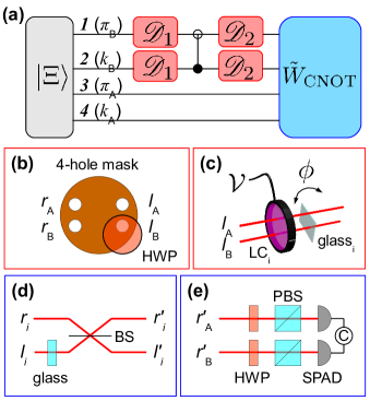
2-qubit separable maps: Experiment — For this second experiment, we used the SPDC source operating over four emission modes (see SI). Hence we prepared the 4-qubit hyperentangled state where and , where () designs the right (left) path of photon or .
We implemented a CNOT gate on Bob’s photon by inserting a half waveplate set at 45∘ on the left path of photon : thus the path (qubit 2) acts as the control and the polarization (qubit 1) acts as the target (Fig. 3 (b)). After the CNOT gate, the 4-qubit state then reads:
| (13) |
Using the correspondence , , and , Eq. (13) is equivalent to the Choi state of the CNOT channel expressed in the logical basis (9).
Dephasing noisy channels were simulated by acting independently on qubits 1 and 2, before and/or after the CNOT gate, as in Eq. (11), by inserting a LC with its fast axis at 0∘ with respect to the horizontal and a thin glass plate, both before and after the CNOT (Fig. 3 (c)). Each LC induces a phase between and , that can be set to either 0 or by applying a voltage or respectively, thus acting either as or for qubit 1; each glass plate introduces a phase between and , that can be set to 0 or by calibrated rotations of the plate, thus acting either as or for qubit 2. By varying the relative time of action of each dephaser, in a similar manner as in the 1-qubit channel experiment, we were able to vary the values of and .
To measure the witness (10) as a function of and , we needed to evaluate and for several values of and . Thus, for each value of and , we measured coincidence counts between photons and in 32 different settings of the polarization-path analysis set-up. The polarization analysis in this case is achieved via a HWP and a PBS (Fig. 3 (e)) while the path analysis is done either directly sending the photons to the detectors (thus measuring and ) or passing them first through a beam-splitter and a thin glass plate (thus measuring and ) (Fig. 3 (d)).
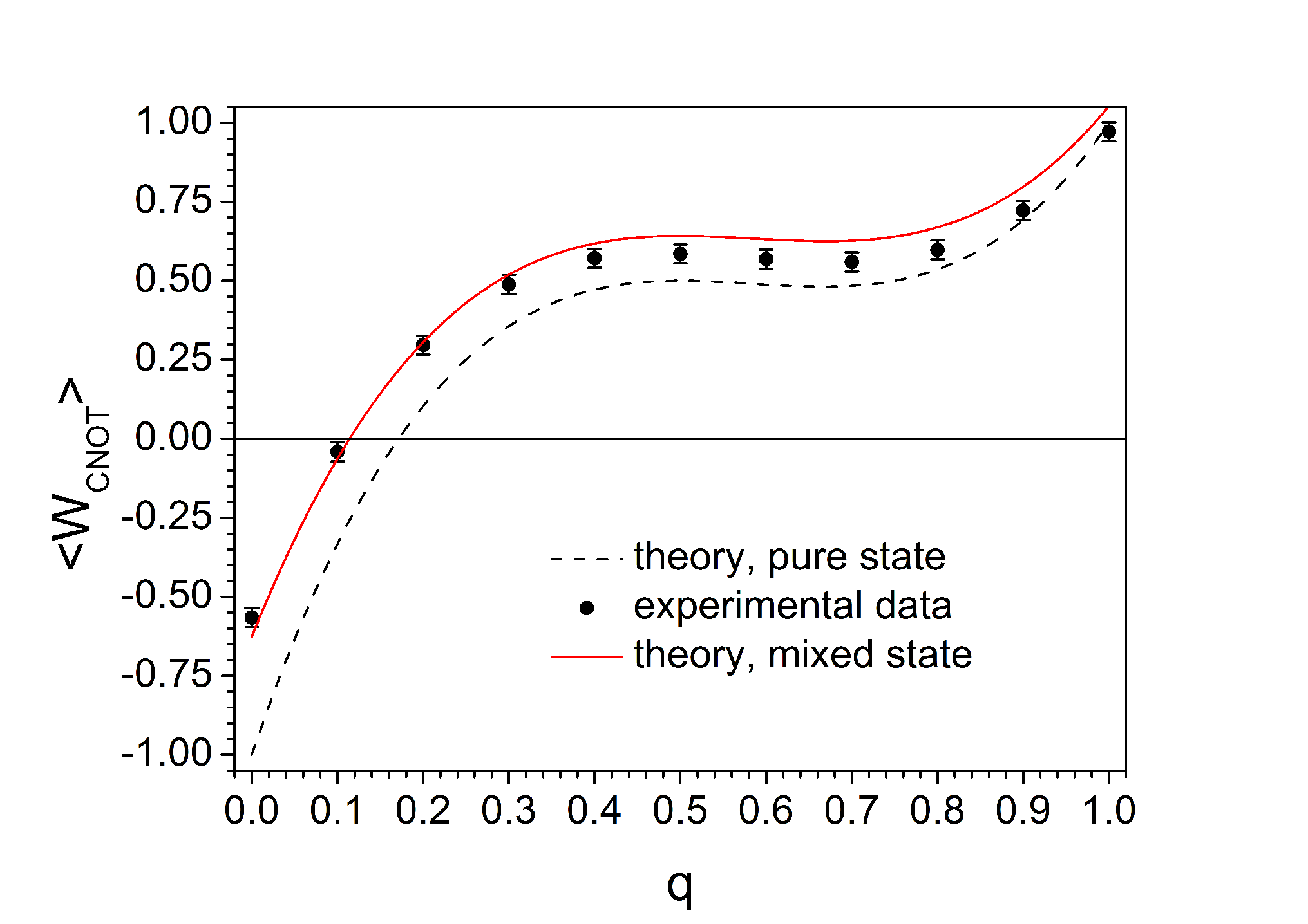
We obtained the witness values reported in Fig. 4 as a function of . Again, to compare them properly with the theory, we must take into account the finite purity of the initial Choi state that we prepared to simulate the Choi state of the CNOT gate. We could model the experimental Choi state of the CNOT noisy channel, given the visibilities (measured in the diagonal basis) of the polarization () and path () entanglement for (see SI). As can be seen, our results are in good agreement with the theoretical calculation. Note that the slight discrepancy remaining for large is probably due to imperfections in the simulated dephasing channels. As expected, from these results it is evident that a low level of noise makes the CNOT to be no more an entangling gate, in particular the non separability of the map is no longer detected for in our experiment.
Conclusion — We have implemented a method that allows to check the entanglement properties of a noisy multi-qubit gate with fewer measurements than those required by a full quantum process tomography JOSAB24gatemeasure and could thus be a more convenient tool for routine performance checks on quantum gates. This method has been tested in the cases of a 1-qubit entanglement breaking channel and of a 2-qubit separable map with very good agreement between experimental measurements and theoretical predictions.
The work was supported by the EU Project QWAD (Quantum Waveguides Applications & Developments).
References
- (1) See, for example M. A. Nielsen and I. L. Chuang, Quantum computation and quantum information, Cambridge University Press, Cambridge (2000).
- (2) C. Macchiavello and M. Rossi, Phys. Scripta T153, 014044 (2013).
- (3) C. Macchiavello and M. Rossi, quant-ph/1208.5121 (2012).
- (4) M. Horodecki, P. Horodecki and R. Horodecki, Phys. Lett. A 223, 1 (1996); B. M. Terhal, Phys. Lett. A 271, 319 (2000).
- (5) A. Jamiolkowski, Rep. Math. Phys. 3, 275 (1972); M.-D. Choi, Linear Algebr. Appl. 10, 285 (1975).
- (6) M. Horodecki, P. W. Shor and M. B. Ruskai, Rev. Math. Phys. 15, 629 (2003).
- (7) O. Gühne, P. Hyllus, D. Bruß, A. Ekert, M. Lewenstein, C. Macchiavello and A. Sanpera, Phys. Rev. A 66, 062305 (2002).
- (8) O. Gühne, P. Hyllus, D. Bruß, A. Ekert, M. Lewenstein, C. Macchiavello and A. Sanpera, J. Mod. Opt. 50, 1079 (2003).
- (9) C. Cinelli, G. Di Nepi, F. De Martini, M. Barbieri, and P. Mataloni, Phys. Rev. A 70, 022321 (2004).
- (10) M. Barbieri, C. Cinelli, P. Mataloni, and F. De Martini, Phys. Rev. A 72, 052110 (2005).
- (11) A. Chiuri, V. Rosati, G. Vallone, S. Pádua, H. Imai, S. Giacomini, C. Macchiavello, and P. Mataloni, Phys. Rev. Lett. 107, 253602 (2011).
- (12) M. Barbieri, F. De Martini, G. Di Nepi, P. Mataloni, G. M. D’Ariano, and C. Macchiavello, Phys. Rev. Lett, 91, 227901 (2003).
- (13) A. De Pasquale and V. Giovannetti, Phys. Rev. A 86, 052302 (2012).
- (14) E. M. Rains, arXiv:quant-ph/9707002 (1998).
- (15) J. I. Cirac, W. Dür, B. Kraus, and M. Lewenstein, Phys. Rev. Lett. 86, 544 (2001).
- (16) Here we implement the Choi state corresponding to the gate CNOT by starting from the maximally entangled state , instead of . This choice, besides not affecting the techniques, will be more convenient in the experimental realization that follows.
- (17) A. G. White, A. Girlchrist, G. J. Pryde, J. L. O’Brien, M. J. Bremner, and N. K. Langford, J. Opt. Soc. B 24, 172 (2007).