Ellipsometry with polarisation analysis at cryogenic temperatures inside a vacuum chamber
Abstract
In this paper we describe a new variant of null ellipsometry to determine thicknesses and optical properties of thin films on a substrate at cryogenic temperatures. In the PCSA arrangement of ellipsometry the polarizer and the compensator are placed before the substrate and the analyzer after it. Usually, the polarizer and the analyzer are rotated to find the intensity minimum searched for in null ellipsometry. In our variant we rotate the polarizer and the compensator instead, both being placed in the incoming beam before the substrate. Therefore the polarization analysis of the reflected beam can be realized by an analyzer at fixed orientation. We developed this method for investigations of thin cryogenic films inside a vacuum chamber, where the analyzer and detector had to be placed inside the cold shield at a temperature of K close to the substrate. All other optical components were installed at the incoming beam line outside the vacuum chamber, including all components which need to be rotated during the measurements. Our null ellipsometry variant has been tested with condensed krypton films on a highly oriented pyrolytic graphite substrate (HOPG) at a temperature of K. We show that it is possible to determine the indices of refraction of condensed krypton and of the HOPG substrate as well as thickness of krypton films with reasonable accuracy.
1 Introduction
Since Alexandre Rothen described the ”Ellipsometer” in 1945 [1], the technique has been developed into a well known procedure to measure film thicknesses and to determine optical properties of a film. Ellipsometry applies light of a well-defined state of polarization that is reflected from the investigated multilayer system. After reflection the state of polarization is analyzed. One application of the technique is the determination of the refractive index of a gas condensed on a surface at low temperature [2]. In this case, the film must not contain impurities and the layer system has to be enclosed in a vacuum chamber.
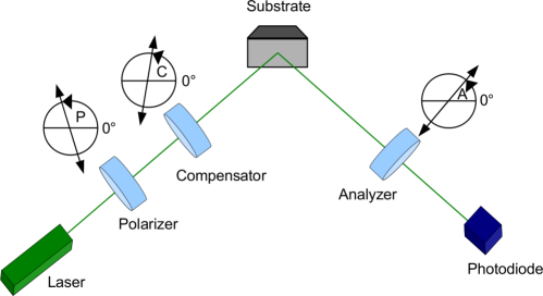
In the past many different variations of ellipsometry set-ups were realized [3]. Because of the arrangement of polarizer, compensator, optical system and analyzer, this commonly used constellation is called ”PCSA” arrangement (see figure 3). In standard applications so-called null-ellipsometry is used: Here the polarizer and the compensator produce elliptically polarized light such that after the reflection at the multilayer system the light is fully linearly polarized. Thus it can be extinguished by an analyzer.
In order to measure thin films with sub-monolayer resolution in a cryogenic ultra-high vacuum environment, a high resolution null-ellipsometry variant has been explored in this work. When measuring thin cryogenic films, using standard experimental arrangements all optical elements remain outside the vacuum chamber at room temperature before and after the multilayer system (e.g. [4, 5]). Whenever this is not possible the method presented here is an interesting alternative. Such a situation could arise if the reflected light after passing the multilayer system would have to be guided out of the vacuum chamber over a large distance before entering the analyzer section. The reason for this could be – like in our case case – a not perfectly flat substrate causing a too large divergence of the reflected beam. To circumvent this problem, the reflected light needs to be analyzed and detected inside the vacuum chamber. If then the analyzer cannot be rotated because of limited space or too low temperatures, the analyzer has to be fixed at a certain angle and the ellipsometry has to be applied in a modified manner.
Our particular PCSA implementation addresses these technical constraints by rotating the compensator in addition to the polarizer and searching for the intensity minimum with a fixed analyzer orientation. As far as we know an ellipsometry variant with fixed analyzer and rotating compensator was presented to be possible in [3] but we haven’t found applications or results of such an ellipsometer in literature111In addition to this variant, a second method solely using a rotating polarizer has been explored [9]. Another variant of ellipsometry is the rotating-compensator Fourier ellipsometer described by Hauge et al.; they utilise a rotated compensator in combination with fixed polarizer and analyzer. [6]. .
It will be shown that this method allows the determination of arbitrary film thickness like the standard PCSA method with rotating analyzer and polarizer. Specifically, we apply this variant of standard PCSA ellipsometry at our conversion electron calibration source for the KATRIN neutrino mass experiment [7]: We condense the krypton isotope 83mKr on a highly-oriented pyrolytic graphite (HOPG) substrate at cryogenic temperatures () under ultra-high vacuum conditions 222Although we usually condense for this application film thicknesses of less than a monolayer, we use ellipsometry with Å-resolution to monitor the cleanliness of the substrate after laser ablation over typical measurement periods of several days. A stable and clean surface is needed to guarantee a conversion electron energy stability and reproducibility of a few 10 meV .. This electron source is positioned inside a superconducting split-coil magnet in a LN2 cooled ultra-high vacuum environment. The reflected light would have to be guided out of the vacuum chamber over a distance of about 2 m. Unfortunately, this is not possible due to the beam divergence caused by the polycrystalline structure of the HOPG substrate333In a predecessor neutrino mass experiment at Mainz similar PCSA ellipsometry has been applied to determine thicknesses of deuterium and tritium films [10, 12]. But because of the problems with the divergent out-going beam the film thickness could only be determined in an offline position before and after the typically two weeks long measurements inside a superconducting magnet.. Therefore the light has to be analyzed and detected inside the vacuum chamber at cryogenic temperatures.
2 Theoretical description
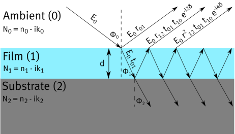
In the following we consider a double layer system consisting of a flat substrate, covered by a homogeneously thick film of thickness (see fig. 3). Following the notation of [3, 8] we describe a dielectric medium by a complex refractive index . With the definition of a plane wave in z-direction of becomes the index of refraction and the extinction coefficient. Thus the absorption coefficient can be expressed by the extinction coefficient () and the vacuum wavelength () as .
We assume that the film can be described by an refractive index with only a negligible extinction . Also for the ambient (usually vacuum or a gas atmosphere) we assume a real index of refraction . Only the substrate is described by a complex index of refraction . The reflection properties of this system are given by the complex reflection coefficients and for the multilayer system [3]
| (1) |
with being the coefficients of single reflection for the various interfaces. These are calculated using the Fresnels formulas for the interfaces between the ambient medium and the film (index ”01”) or between the film and the substrate (index ”12”) for perpendicular (denoted ”s”) and parallel (denoted ”p”) polarized waves with respect to the plane of incidence. The coefficients depend on the indices of refraction of the regarded interface and the angle of incidence . For a vacuum wavelength of the laser, the film thickness causes a phase shift :
| (2) |
As usual and constitute the rotation angles of the polarizer and analyzer as defined by the orientation of transmitted polarized light with respect to the plane of incidence (see figure 3). is the angle between the fast axis of the compensator and the plane of incidence. If the compensator is a quarter wave plate the light intensity behind the analyzer is given by [3]
Two of the three angles , , are defined by the condition of null intensity , while the third one can be chosen freely in most cases. Then the properties of the system are described by
| (4) |
Usually the compensator angle is set to resulting in
| (5) |
In the following we call this method ”PA ellipsometry”, in which the compensator is fixed to while the the polarizer and the analyzer are varied in order to find an intensity minimum.
For more detailed information we refer to reference [3]. We would like to note that in the literature the complex variable is often expressed as
| (6) |
where corresponds to the absolute value and to the complex phase of in the polar expression. In the modified variant of PCSA ellipsometry, which was outlined in the introduction, the analyzer remains fixed at a certain angle and the compensator angle is varied. We still consider the compensator to be a quarter-wave plate. Therefore, equation (4) still holds but not equation (5). In order to prove that we can obtain null intensity by varying the polarizer and compensator angles and we plot the intensity as function of and for different krypton film thicknesses in figure 4.
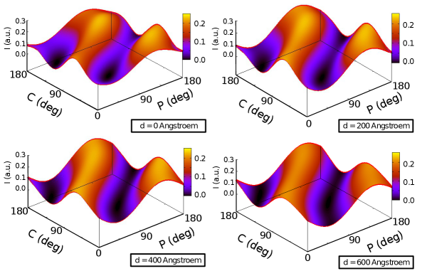
It shows indeed, that for all film thicknesses regions with null-light intensity can be found. But figure 4 also illustrates that the minima might be flat, thus limiting the sensitivity. Like in PA ellipsometry we see again two minima, now in the -plane444 Of course, figure 4 only shows some exemplary simulations to demonstrate these statements, but it is not a full mathematical proof.. We are determining the minimum of the light intensity as function of the polarizer and compensator angles and for a fixed analyzer angle . From now on we call this method ”PC ellipsometry”. Via equation (4) the angles and define a complex variable . In order to facilitate the determination of the corresponding film thickness we define two corresponding angles and .
Similar to Euler‘s representation, we generally can express any complex number by two angles as
| (7) |
Therefore we can translate our angles and defining the intensity minimum for a given film thickness into the corresponding angles and via:
| (8) |
The left-hand side of equation (8) looks identical to equation (5) for . This means, if a film thickness would be characterized by a pair (,) in PC ellipsometry, the transformation with equation (8) describes which angles and would have been encountered in standard PA ellipsometry for the same film thickness. The advantage of this transformation is that one can use the same data analysis tools as for PA ellipsometry.
3 Experimental set-up
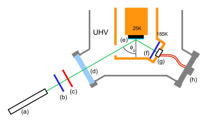
A schematic overview of the experimental set-up is shown in figure 2 555The real set-up uses two cold shields - an inner cold shield at 12 K and an outer cold shield at 90 K. For a better overview the inner cold shield was neglected in figure 2.. The light source is a HeNe laser ( nm, P mW) followed by a neutral density filter, a linear polarizer and a quarter-wave plate producing circular polarized light. All these components are summarized in figure 2 as (a). The circular polarization of the laser light in combination with a second rotatable polarizer (b) allows to choose any angle of polarization without a change of intensity. After the polarizer the light beam passes the compensator (c). The latter two components are mounted on rotation tables.
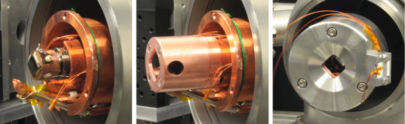
The substrate (10 mm 10 mm) is grade SPI-2 HOPG (SPI Supplies) with a mosaic angle of . The substrate is glued to a copper holder using electrically-conductive silver epoxy (Polytec H20E). The holder is cooled by a two-stage cryocooler of the Gifford McMahon-type (Sumitomo Heavy Industries Ltd., model RDK 408D). The first stage has a cooling power of 34 W at 40 K, the second stage provides a cooling power of 1 W at 4 K. The outer cold shield is connected to the first stage. The second stage cools the substrate and the inner cold shield. The temperature of the substrate, measured by a LakeShore DT-670B-SD temperature sensor mounted on the copper block that holds the substrate, can be set to an arbitrary value above 20 K by heating. To avoid birefringence of cold optical windows, both cold shields have free entrance and exit openings for the ellipsometry laser. At the exit opening of the outer cold shield the analyzer and the detector are mounted as shown in figure 5. The analyzer is a linear polarizer of 12 mm diameter and 0.28 mm thickness (Thorlabs LPVISB050, not laminated). The temperature at the analyzer is about 90 K (with a maximum gradient of 0.6 K/min during cool down.). The detector is a 9 9 mm2 windowless Si-PIN photodiode (Hamamatsu S-3590-19) read out by a current amplifier (Femto DLPCA-200). The other relevant optical components are the polarizer (PGT 2.05 Bernhard Halle Nachfolger GmbH - optische Werkstätten) and the compensator (CVI Melles Griot QWPM-543-04-4-R10)
After a full bake-out cycle of the set-up at a temperature of 423 K we prepared condensed films on the substrate. This was done by letting gas from a buffer volume with pressure of 2 mbar diffuse during short opening periods through a regulating valve (Pfeiffer UDV 146) and a heated capillary, which ends a few cm above the substrate surface. Different settings of the pressure in the buffer volume (typically 2 mbar) and the opening width and period of the dosing valve produce different step sizes in film thickness. For our investigations we use standard krypton gas (purity 4.7).
To clean the surface of the HOPG substrate a combination of resistive heating and laser ablation was used. The resistive heating was done by a TVO resistor up to 400 K. This temperature was held for about an hour before the laser ablation was started with a power density of 180 mWcm-2 for 2-20 min. During the ablation the temperature was kept at 400 K.
The ablation set-up consists of a frequency doubled Nd:YAG laser (QUANTEL Brilliant), a Glan Laser polarizer (GL 10-A Thorlabs), high reflective mirrors and a beam homogenizer (SUSS CC-Q-300). The ablation laser provides pulses of 5 ns duration and of 200 mJ energy, at a repetition rate of 10 pulses per second. The power was reduced by a Glan laser polarizer to reach the desired power density at the substrate. The beam was homogenized by a high power beam homogenizer made of crossed cylindrical lens arrays to homogeneously illuminate the whole substrate.
To obtain the absolute start values the angle of the compensator was calibrated. This was done by using the ellipsometry laser, a linear polarizer, the compensator and another polarizer serving as analyzer. With the linear polarized light from the polarizer a circular polarized beam was prepared with the compensator. The residual linear polarization was measured by turning the analyzer by up to 180∘ and measure the intensity. The compensator was set to different angles to find the position, for which complete circular beam polarization could be achieved. The flattest measured curve defined the 45∘ position of the compensator corresponding to circular polarisation.
Before each measurement series was started the gas chamber was baked at K to provide a clean environment. For each film the gas chamber was evacuated and filled with fresh gas to about 2 mbar. The purity of the used krypton was permanently monitored by a residual gas analyzer (RGA).
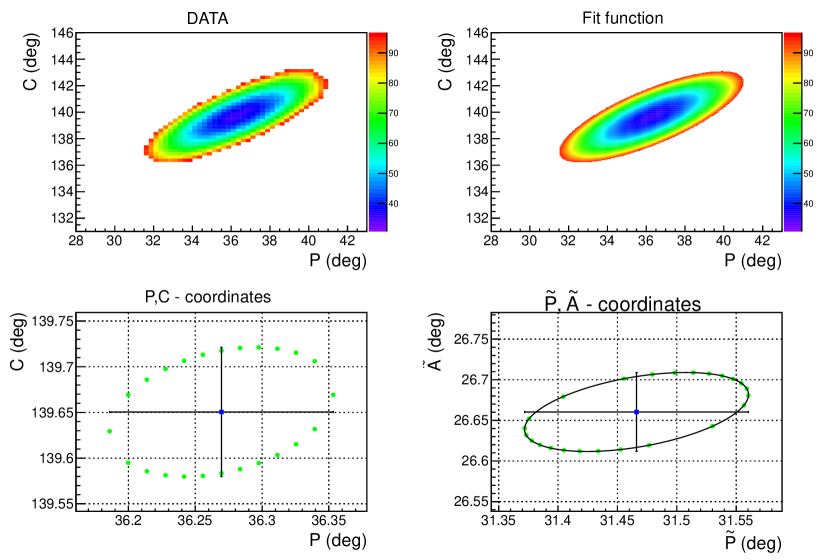
During the measurement it turned out that the iterative online minima search from the PA ellipsometry was not precise enough to find the correct minima because of the rather flat and broad PC minima (as shown in figure 4). Hence the area of 10∘ (7.5∘) around the minima, found by the iterative method, was scanned with a typical step size of 1∘ (0.25∘). These data were analysed offline by fitting them, using a paraboloid locally around the minimum (see figure 6). The typical errors of the position in coordinates are below . These errors are obtained from the least square fit and multiplied by 666This correction using ( is the number of degrees of freedom of the fit) is applied, since the size of the uncertainties of the intensity measurement is unknown but considered to be constant for all data points of a measurement.. To obtain the uncertainties and the corresponding correlation after the transformation to - coordinates, the points of the error ellipse in PC coordinates were also transformed and fitted (figure 6 lower right). This analysis was done for each condensed layer of krypton to obtain the intensity minima , their uncertainties () and the correlation () for the whole condensation process.
4 Experimental results
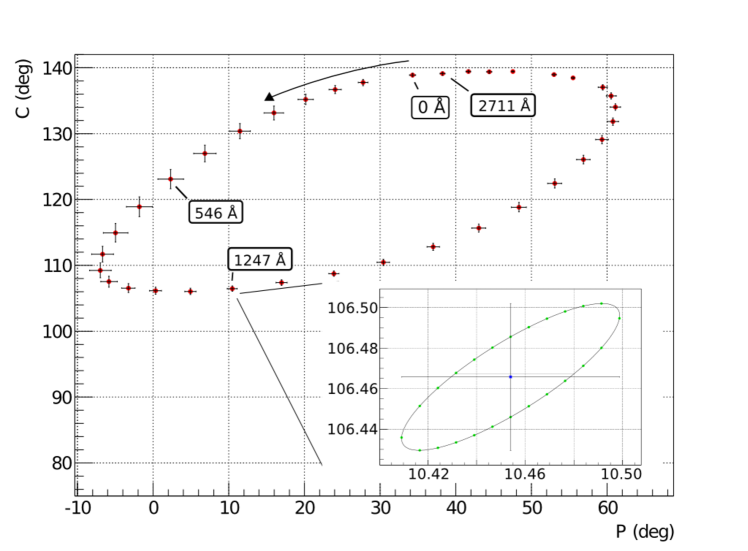
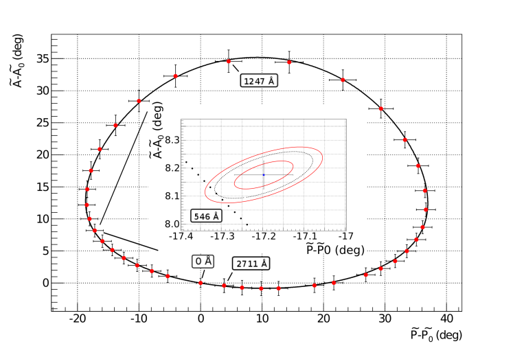
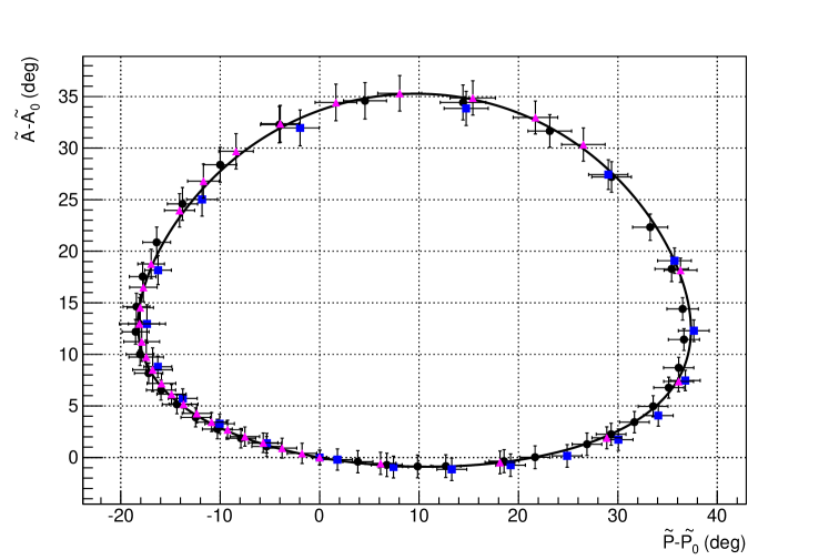
For the investigation of the PC ellipsometry three different measurement series (H, HA, HAN - for their meaning see further below) were carried out. For all measurements a krypton film of about 3000Å thickness was condensed in about 15-30 steps. After each step a PC ellipsometry was carried out yielding an intensity minimum . The results of a complete measurement is shown in figure 7. With the help of equation (8) these minima were transformed into the minima in coordinates as shown in figure 6. All datasets were corrected for a substrate tilted with respect to the plane of incident, as well as for angular offsets of the polarizer, compensator and analyzer. The uncertainties of these offsets were treated as systematic errors.
The conditions for the three measurement series are as follows (more details about differences between these measurement series will be given below in this section.):
-
1.
Measurements H1-H4:
For these measurements the substrate was cleaned only by heating the substrate to about 400 K. -
2.
Measurements HA1-HA3:
A combination of heating of the substrate to about 400 K and ablation was used to clean the surface of the HOPG. -
3.
Measurements HAN1-HAN6:
To improve the reproducibility of the PC ellipsometry a new set of measurements was executed as for HA1-HA3, but with these differences:-
(a)
The substrate was freshly cleaved
-
(b)
P and C were scanned in a range of with a step size of instead of a range of with a step size of .
-
(c)
The heating temperature was raised to approx. 500 K before and during ablation
-
(a)
The optical constants of HOPG as well as those of condensed krypton films were also obtained from a fit to the measured intensity minima as shown in figure 8. First many theoretical curves or respectively, were calculated and compared to the measurements. This was done by varying the optical constants of HOPG and the index of refraction of krypton . The angle of incident and the absorption coefficient of krypton were kept fix during analysis. For each variation the ratio of the two reflection coefficients (equation (4)) was calculated in 1 Å steps. From this the () values were derived using equation (5). The curve with the smallest distance to the intensity minima yields the values for the optical constants. The correct distance between an intensity minimum and the fit curve normalized to the uncertainties is given by:
The distance calculations takes also the correlation coefficient of the uncertainties and into account. The summed distance is minimized in the fit. It should be noted that the fit uses relative values in and coordinates by subtracting the corresponding values for zero film thickness and respectively. We have not considered this detail in equation (4) for the sake of convenience to read this equation.
The fit to the corresponding angles yields the refractive indices of the condensed krypton film and the optical constants of the HOPG substrate (see table 1). These fits like shown in figure 8 yield which point to unrecognised systematic errors. Possible sources of these are a possible surface roughness, impurities, porosity of the film. Unfortunately our not complete knowledge of these effects does not allow a correction of these systematics. To account for their influence on the fit results, we scale the fit uncertainties with . Although HOPG is an anisotropic material we describe it by only one isotropic refraction index instead of ordinary and extraordinary refractive indices. The results of all three measurements of series HA are shown in figure 9.
In addition to the HA-series some HAN-series measurements were performed, in order to see whether our method could be improved further by increasing the heating temperature of the substrate to about 500 K. The increased substrate temperature during ablation can help to get a cleaner surface because the heat conductivity of HOPG out of plane decreases and the conductivity in plane increases with increasing temperature [11]. Therefore, the energy of the ablation laser pulses are transferred less into the substrate and is dissipated mostly at the surface. In addition, the step size of the - and -scanning was reduced to to obtain a more precise minimum.
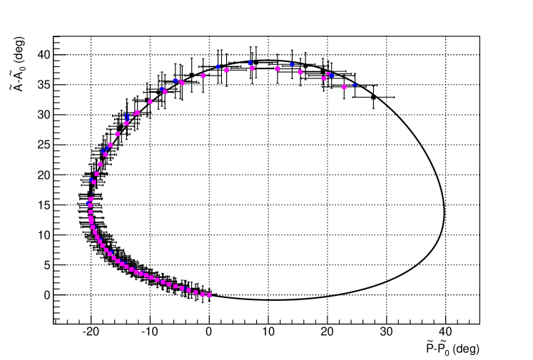
Both changes lead to a higher reproducibility of the measured data but resulted in a much longer time span to measure one complete condensation of a film up to 3000 Å thickness. Unfortunately the residual gas pressure of water in the vacuum chamber was higher during this measurement series thus the data could not be analysed for very large film thickness, because water was condensing onto the film. The whole condensing procedure took more than 24 hours due to the elaborate minimum search caused by the fine step size. This condensing water caused a non-closed curve in or coordinates for a krypton film. Therefore we limited our analysis to film thickness up to 1400 Å only. The results of all analysed data points are shown in figure 10.
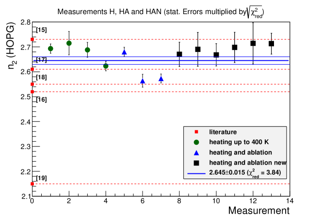
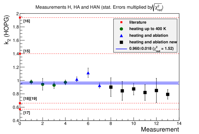
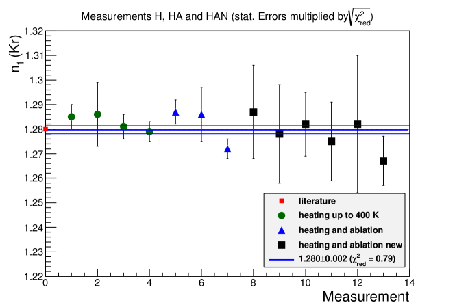
Our previous investigations showed that the combination of laser ablation and heating leads to the most stable measurements in comparison to other cleaning methods 777We would like to note, that the proper cleaning not only affects the index of refraction of HOPG but also those of the krypton film.. Figures 11 and 12 show the results of the optical parameters of HOPG and of krypton from all of our measurements. The results from the measurements within a series and between the three measurements series are consistent with each other but still the average exhibit higher than expected. To account for this we scale the fit error with . These results from figures 11 and 12 are compared with literature values in table 1.
The refractive index of solid krypton deviates from most of the literature values. In the Mainz Neutrino Mass Experiment a similar deviation of the refractive index of tritium was observed, measured by ellipsometry as well as by measurements of the energy loss of electrons in quench condensed deuterium films [12]. This observation was explained by a porous film due to the quench condensation of the tritium gas. So we calculate the density of the kryton films with the help of Clausius Mosotti‘s equation:
| (10) |
and the measured index of refraction the density of our krypton film:
| (11) |
Using the polarizability cm3 [14] and the molar mass () of krypton we obtain a density of our krypton film of:
This is about 23% less than the expected value of [23]. Therefore the film can be assumed to be porous due to the quench condensation of the krypton gas, as in the case of the quench condensed tritium and deuterium films [12].
The results show a reasonable agreement of our measured optical refractive indices for krypton and HOPG with values reported in the literature, for both krypton and HOPG (see column 3 of Table 1). Specially one finds: (at 633 nm)[18], (at 546 nm) [19], (633 nm)[20] taken from [22], (at 633 nm) [21] and (at 541 nm)[22] yielding the ranges and (see table 1). For the refractive index of krypton only the results of Kruger [2] are shown because most of the other values in literature are measured with different techniques and thus lead to different results. Due to the quench condensation of krypton the film might be porous and this might lead to a lower index of refraction. The values obtained from different methods e.g. measurements with refractometers leads to a index of refraction of n1=1.375 [13].
| refractive | this work | literature |
|---|---|---|
| index | ||
| 1.28* | ||
| 2.15–2.73 | ||
| 0.57–1.94 |
5 Conclusion and outlook
In this paper, we presented a new variant of ellipsometry, which we dubbed PC-ellipsometry since
the polarizer and the compensator are rotated to find the intensity minimum, where the analyzer behind the substrate remains at fixed angle. This method allows a simple polarisation analysis close to the substrate
even at cryogenic temperatures inside a vacuum chamber. We determined
the optical constants of condensed krypton and of the HOPG substrate that are consistent with literature values.
We demonstrated that thicknesses of condensed krypton films up to 3000 Å can be determined.
Our results show that PC ellipsometry can reach accuracies similar to that of standard PA ellipsometry.
We propose a transformation of the intensity minima of PC ellipsometry into coordinates, which allows one use the same evaluation tools as for PA ellipsometry.
The described ellipsometry set-up is designed to operate at the KATRIN experiment. Due to the temperature of 77 K at the site of operation inside a superconducting split-coil magnet, the use of vacuum windows with direct sight onto the substrate is impossible. We will use the new method to carry out the polarisation analysis inside the setup. The incoming polarized laser beam will be guided by one or two mirrors onto the substrate. The mirrors will be placed behind the polarizer and the compensator onto the substrate. It should be noted that in general dielectric mirror coating do influence the polarisation state of any incident light beam. However, for our high-precision mirrors (Laseroptik 11028J1) we found that these particular coatings preserved a defined polarization state well enough to perform accurate PC ellipsometry.
Acknowledgment
The KATRIN experiment is supported by the Bundesministerium für Bildung und Forschung (BMBF) under the contract number 05A08PM1.
Appendix A
| Meas. | |||||
|---|---|---|---|---|---|
| H1 | () | () | () | 7.1 | |
| H2 | () | () | () | 45.5 | |
| H3 | () | () | () | 25.5 | |
| H4 | () | () | () | 4.6 | |
| HA1 | () | () | () | 7.1 | |
| HA2 | () | () | () | 13.6 | |
| HA3 | () | () | () | 4.9 | |
| HAN1 | () | () | () | 14.5 | |
| HAN2 | () | () | () | 16.2 | |
| HAN3 | () | () | () | 3.2 | |
| HAN4 | () | () | () | 16.5 | |
| HAN5 | () | () | () | 21.5 | |
| HAN6 | () | () | () | 10.6 |
| d (Å) | P (∘) | C (∘) | ||||||||
|---|---|---|---|---|---|---|---|---|---|---|
| 0 | 34.570 | 138.672 | 0.069 | 0.051 | 0.560 | 30.799 | 27.275 | 0.059 | 0.036 | 0.185 |
| 122 | 28.020 | 137.499 | 0.068 | 0.051 | 0.557 | 25.467 | 28.346 | 0.058 | 0.033 | 0.180 |
| 188 | 24.288 | 136.389 | 0.068 | 0.051 | 0.562 | 22.882 | 29.145 | 0.058 | 0.031 | 0.189 |
| 255 | 20.455 | 134.940 | 0.071 | 0.054 | 0.586 | 20.515 | 30.034 | 0.059 | 0.031 | 0.205 |
| 326 | 16.146 | 132.774 | 0.070 | 0.053 | 0.577 | 18.331 | 31.166 | 0.058 | 0.029 | 0.286 |
| 397 | 11.634 | 129.992 | 0.068 | 0.051 | 0.560 | 16.440 | 32.430 | 0.057 | 0.028 | 0.413 |
| 470 | 7.028 | 126.644 | 0.074 | 0.057 | 0.619 | 14.847 | 33.805 | 0.057 | 0.032 | 0.480 |
| 546 | 2.363 | 122.604 | 0.070 | 0.053 | 0.585 | 13.602 | 35.451 | 0.054 | 0.035 | 0.615 |
| 623 | -1.740 | 118.451 | 0.072 | 0.055 | 0.606 | 12.734 | 37.287 | 0.052 | 0.041 | 0.642 |
| 704 | -4.908 | 114.472 | 0.072 | 0.055 | 0.607 | 12.290 | 39.463 | 0.050 | 0.048 | 0.631 |
| 782 | -6.569 | 111.298 | 0.072 | 0.056 | 0.606 | 12.377 | 41.903 | 0.049 | 0.054 | 0.574 |
| 860 | -6.886 | 108.785 | 0.068 | 0.051 | 0.562 | 13.000 | 44.813 | 0.048 | 0.059 | 0.540 |
| 935 | -5.702 | 107.128 | 0.069 | 0.052 | 0.566 | 14.407 | 48.135 | 0.053 | 0.065 | 0.445 |
| 1011 | -3.014 | 106.270 | 0.070 | 0.052 | 0.570 | 17.001 | 51.865 | 0.060 | 0.071 | 0.358 |
| 1083 | 0.555 | 105.904 | 0.068 | 0.051 | 0.560 | 20.799 | 55.660 | 0.069 | 0.076 | 0.311 |
| 1162 | 5.216 | 105.830 | 0.069 | 0.051 | 0.559 | 26.749 | 59.551 | 0.083 | 0.080 | 0.281 |
| 1247 | 11.035 | 106.397 | 0.069 | 0.051 | 0.561 | 35.364 | 61.864 | 0.098 | 0.080 | 0.258 |
| 1334 | 17.392 | 107.266 | 0.070 | 0.052 | 0.564 | 45.222 | 61.704 | 0.105 | 0.077 | 0.209 |
| 1421 | 23.987 | 108.490 | 0.071 | 0.053 | 0.570 | 53.949 | 58.936 | 0.099 | 0.070 | 0.107 |
| 1506 | 30.724 | 110.302 | 0.073 | 0.054 | 0.587 | 60.164 | 54.476 | 0.088 | 0.064 | -0.008 |
| 1592 | 37.382 | 112.767 | 0.068 | 0.051 | 0.556 | 64.049 | 49.612 | 0.075 | 0.053 | -0.077 |
| 1672 | 43.113 | 115.445 | 0.072 | 0.054 | 0.583 | 66.210 | 45.563 | 0.070 | 0.050 | -0.114 |
| 1763 | 48.883 | 118.937 | 0.068 | 0.051 | 0.557 | 67.313 | 41.682 | 0.064 | 0.041 | -0.125 |
| 1846 | 53.390 | 122.378 | 0.070 | 0.053 | 0.575 | 67.447 | 38.714 | 0.063 | 0.039 | -0.066 |
| 1936 | 57.336 | 126.117 | 0.068 | 0.051 | 0.561 | 66.917 | 35.980 | 0.060 | 0.035 | 0.016 |
| 2007 | 59.618 | 129.014 | 0.069 | 0.052 | 0.569 | 65.917 | 34.048 | 0.060 | 0.035 | 0.097 |
| 2083 | 61.021 | 131.763 | 0.069 | 0.052 | 0.571 | 64.347 | 32.242 | 0.059 | 0.036 | 0.159 |
| 2154 | 61.467 | 134.014 | 0.069 | 0.051 | 0.565 | 62.462 | 30.706 | 0.058 | 0.037 | 0.203 |
| 2224 | 60.744 | 135.629 | 0.070 | 0.053 | 0.572 | 60.118 | 29.531 | 0.059 | 0.039 | 0.215 |
| 2289 | 59.535 | 136.863 | 0.070 | 0.053 | 0.573 | 57.696 | 28.563 | 0.059 | 0.040 | 0.221 |
| 2411 | 55.732 | 138.312 | 0.070 | 0.052 | 0.565 | 52.467 | 27.302 | 0.059 | 0.042 | 0.216 |
| 2477 | 53.021 | 138.713 | 0.071 | 0.053 | 0.573 | 49.344 | 26.919 | 0.060 | 0.043 | 0.209 |
| 2594 | 47.782 | 139.274 | 0.069 | 0.052 | 0.566 | 43.492 | 26.435 | 0.059 | 0.042 | 0.213 |
| 2650 | 45.052 | 139.345 | 0.071 | 0.052 | 0.572 | 40.658 | 26.413 | 0.060 | 0.041 | 0.191 |
| 2711 | 41.899 | 139.264 | 0.076 | 0.056 | 0.605 | 37.556 | 26.552 | 0.063 | 0.043 | 0.147 |
References
References
- [1] A Rothen 1945 The Ellipsometer, an Apparatus to Measure Thicknesses of Thin Surface Films Rev. Sci. Instrum. 39 26-30
- [2] J Kruger and W Ambs, Optical Measurements on Thin Films of Condensed Gases at Low Temperatures, J. Opt. Soc. Am. 49, 1195-1198 (1959).
- [3] R M A Azzam and N M Bashara 1987 Ellipsometry and polarized light Elsevier-North Holland Library
- [4] T McMillan, P Taborek and J E Rutledge 2004 A low drift high resolution cryogenic null ellipsometer Rev. Sci. Instrum. 75 5005-5009
- [5] Ch Kraus, B Bornschein, L Bornschein, J Bonn, B Flatt, A Kovalik, B Ostrick, E W Otten, J P Schall , T Thümmler, C Weinheimer 2005 Final Results from phase II of the Mainz Neutrino Mass Search in Tritium Decay Eur. Phys. J. 40 447
- [6] P S Hauge and F H Dill 1975 A rotating-compensator fourier ellipsometer, Optics Communications 14 No 4 431-437
- [7] J Angrik et al. (KATRIN Collaboration) 2004 KATRIN Design Report Wissenschaftliche Berichte FZ Karlsruhe 7090, http://bibliothek.fzk.de/zb/berichte/FZKA7090.pdf
- [8] O S Heavens 1991 Optical properties of thin solid films Dover Publications
- [9] U G Volkmann and K Knorr 1989 Ellipsometric study of Krypton physisorbed on graphite Surf. Sci. 221 3791
- [10] B Bornschein, J Bonn, L Bornschein, E W Otten, C Weinheimer, Self-Charging of Quench Condensed Tritium Films, J. Low Temp. Phys., Vol. 131 (2003) 69
- [11] J. -P. Issi, J. Heremans, M. S. Dresselhaus, Electronic and lattice contributions to the thermal conductivity of graphite intercalation compounds, Phys. Rev. B 27 1333-1347
- [12] V.N. Aseev, A.I. Belesev, A.I. Berlev, E.V. Geraskin, O.V. Kazachenko, Yu.E. Kuznetsov, V.M. Lobashev, R.P. Ostroumov, N.A. Titov, S.V. Zadorozhny, Yu.I. Zakharov, J. Bonn, B. Bornschein, L. Bornschein, E.W. Otten, M. Przyrembel, Ch. Weinheimer, A. Saenz, Energy loss of 18 keV electrons in gaseous T2 and quench condensed D2 films, Eur. Phys. J. D 10 (2000) 39
- [13] A C Sinnock 1980 Refractive indices of the condensed rare gases, argon, krypton and xenon J. Phys. C: Solid State Phys. 13 2375-2391
- [14] C Kittel 2005 Einführung in die Festkörperphysik Oldenbourg
- [15] A Hibbert, KL Bell and K A Berrington 1987 The atomic polarisability of krypton and xenon J. Phys. B, At. Mol. Phys. 20 L349
- [16] E A Guggenheim, M L McGlashan 1960 Equilibrium properties of crystalline argon, krypton and xenon Molecular Physics 3 563-570
- [17] B F Figgins, B L Smith 1960 Density and Expansivity of Solid Krypton Phil. Mag. 5:50 186
- [18] D L Greenway, G Harbeke 1969 Anisotropy of the Optical Constants and the Band Structure of Graphite Phys. Rev. 178 No 3
- [19] GE Jellison, J D Hunn Jr, Ho Nyung Lee 2007 Measurement of optical functions of highly oriented pyrolytic graphite in the visible Phys. Rev. B 76 085125
- [20] E A Taft and H R Philipp 1965 Optical Properties of Graphite, Phys. Rev. 138 A197-202
- [21] M Berman, H Kerchner and S Ergun, Determination of the Optical Properties of Absorbing Uniaxial Crystals from Reflectance at Oblique Incidence, J. Opt. Soc. Am. 60, 646-648 (1970).
- [22] S Ergun 1967, Determination of Longitudinal and Transverse Optical Constants of Absorbing Uniaxial Crystals–Optical Anisotropy of Graphite, Nature 213, 135-136
- [23] Beaumont et al., Thermodynamic Properties of Krypton. Vibrational and Other Properties of Solid Argon and Solid Krypton, 1961 Proc. Phys. Soc. 78 1462