Efficient Computation of Power, Force, and Torque in BEM Scattering Calculations
Abstract
We present concise, computationally efficient formulas for several quantities of interest—including absorbed and scattered power, optical force (radiation pressure), and torque—in scattering calculations performed using the boundary-element method (BEM) [also known as the method of moments (MOM)]. Our formulas compute the quantities of interest directly from the BEM surface currents with no need ever to compute the scattered electromagnetic fields. We derive our new formulas and demonstrate their effectiveness by computing power, force, and torque in a number of example geometries. Free, open-source software implementations of our formulas are available for download online.
I Introduction
This paper presents concise new formulas for the absorbed and scattered power, force (radiation pressure), and torque exerted on material bodies by incident fields. Our formulas, which are derived in the context of the frequency-domain boundary-element method [BEM, also known as the method of moments (MOM)], express powers, forces, and torques (PFTs) in terms of vector–matrix–vector products involving the vectors of BEM surface-current coefficients and certain sparse matrices describing basis-function overlaps. We present the derivation of our formulas and apply them to a number of example geometries.
The primary goal of electromagnetic scattering solvers is to compute the electric and magnetic fields in a given material geometry illuminated by given incident fields or sources. However, in many cases we are less interested in the fields themselves than in certain derived quantities obtained from them. For example, in a scattering problem we may be more interested in the total absorbed power or the total scattering cross section than in the individual fields at particular points in space [1, 2]. Similarly, for the problem of a mesoscopic structure [3, 4] or nanoparticle [5, 6, 7] illuminated by a laser, we may seek the force or torque exerted on the particle by the incident-field sources.
Of course, derived quantities such as power, force, and torque may always be computed indirectly in any scattering formalism by first computing the scattered fields and then post-processing: powers and forces/torques are obtained respectively by integrating the Poynting vector (PV) and the Maxwell stress tensor (MST) over a bounding surface surrounding the object in question, with values of the PV and MST at each surface point computed using field components obtained from the scattering solver. However, in practice the integration may be numerically badly behaved due to large cancellations from different regions of the bounding surface, requiring large numbers of cubature points to obtain accurate results. Moreover, in scattering formalisms such as the BEM—where, unlike other techniques such as the finite-difference and finite-element methods, the fields are not computed directly as part of the solution to the problem—each field evaluation required to evaluate the PV or MST integrals by numerical cubature costs extra work.
To date a variety a methods have been used to compute PFTs for compact bodies. For bodies of highly symmetric shapes such as spheres or cylinders, exact results are available in analytical form (such as Mie theory for spheres) [8, 9], and these closed-form solutions may be used to compute PFTs for such bodies [10, 11, 12, 13], or extended to the case of spheroidal bodies [14]. For bodies small compared to the incident wavelength (“Rayleigh particles”), PFTs may be computed using quasistatic approximations [15, 16, 17, 18, 19], while in the opposite regime (bodies large compared to the incident wavelength) the geometrical-optics approximation is available [20, 21, 22]. Radiation forces for nonspherical bodies have also been computed using quasi-analytical approaches (numerical methods based on analytical solutions for special geometries), including T-matrix methods [23] and discrete dipole approximations [24], Among fully numerical techniques, compact-object PFTs have been computed using finite-difference time-domain (FDTD) methods [25, 3, 7, 26, 27] and finite-element methods [28, 29, 30].
BEM techniques have been used by several authors to characterize local power absorption [31, 32, 33, 34], and were used in Ref. 35 to compute total cross sections for scattering and absorption by a compact body. Ref. 4 employed a BEM technique to investigate the force and torque on a mesoscopic body illuminated by a laser beam, while Ref. 36 used the BEM to compute radiation forces on two-dimensional structures. In all of these BEM studies, the standard BEM approach was applied to solve for surface currents, after which the surface currents were used to compute scattered fields. The total absorbed/scattered power [35] or force [4, 36] was obtained by numerically evaluating a surface integral over the body or over a bounding surface.
An alternative BEM approach to the computation of absorbed power was suggested by Ref. 37, which noted that the power absorbed by a compact body may be obtained directly from the surface currents, obviating the intermediate step of computing scattered fields. (This observation seems to have been mentioned as something of a passing curiosity in Ref. 37; although the authors note that the absorption may be computed directly from the surface currents, computational details are omitted, and thereafter the authors revert to the usual practice of obtaining absorption and other quantities via the intermediate device of computing scattered fields.)
The objective of this paper is to extend the observation of Ref. 37 by demonstrating that, in the BEM framework, powers, forces, and torques (PFTs) may be computed directly from the surface currents that are the primary output of the BEM solver. This approach bypasses unwieldy numerical cubatures of the PV and MST, yielding concise formulas expressing PFTs in terms of vector–matrix–vector products (VMVPs). The vectors that enter these expressions are just the RHS vector and the solution vector of the linear BEM system, while the matrices describe various overlaps of the surface-current basis functions and have the virtue of being highly sparse for localized basis functions (including the commonly used Rao-Wilton-Glisson (RWG) functions [38]). The upshot is that we can compute PFTs immediately upon assembling and solving the linear BEM system, with no need ever to compute a scattered field.
In addition to the theoretical compactness and practical convenience of our formulas, their computational impact is to render essentially negligible the cost of evaluating PFTs beyond the base cost of solving the linear BEM system. More specifically, for a BEM scattering problem with surface currents expanded in a basis of localized functions (such as RWG functions), our PFT algorithms entail computational cost scaling like with a small constant prefactor once the linear BEM system has been solved. Of course, in geometries involving only a single body—or multiple bodies in which we require only aggregate PFTs for the collection of all bodies—PFTs may generally be computed in time by evaluating numerical cubatures of the PV or MST over distant bounding surfaces. In this case, the distance of the bounding surface enables the use of numerical cubature with a number of evaluation points that is independent of the fineness of the mesh discretization; the computational cost would then be just that of evaluating the scattered fields at each cubature point, an procedure in BEM. However, in cases involving closely-spaced bodies in which we require individual PFTs for each body—such as the two closely-spaced nanoparticles of Figure 3—numerical cubature of the PV or MST over a bounding surface surrounding just one body would presumably require large numbers of cubature points in the region between the two bodies, and indeed the number of cubature points may grow as the mesh is refined, which would increase the computational cost scaling to Moreover, asymptotic considerations aside, in practice the computation of PFTs via surface integration of the PV or MST entails the cumbersome steps of defining a bounding surface and implementing a multidimensional numerical cubature with an unwieldy integrand. These complications are entirely bypassed by the concise VMVP formulas we present here.
Our VMVP formulas for PFTs are closely related to certain determinant and trace formulas for Casimir forces and radiative heat-transfer rates arising in the “fluctuating-surface-current” (FSC) approach to fluctuation phenomena [39, 40, 41]. The FSC approach addresses problems involving thermal and quantum-mechanical fluctuations in the electromagnetic field; the present paper may be viewed as an exploration of the applications of FSC ideas to classical scattering calculations.
The remainder of this paper is organized as follows. In Section II we derive VMVP formulas for the power absorbed by and scattered from objects irradiated by external fields. In Section III we derive VMVP formulas for the force and torque exerted on objects by external fields. In Section IV, we first validate our formulas by using them to reproduce known results for spheres, where Mie theory may be used to compute PFTs analytically. Then we illustrate the usefulness of our formulas by applying them to bodies of complicated shapes for which other methods of computing PFTs would be unwieldy. Our conclusions are presented in Section V. Appendix A presents an alternative physical interpretation of the power formulas derived in Section II, which has the added benefit of leading to an alternative VMVP formula for the scattered power.
The formulas derived in Sections II and III involve matrices whose entries are overlap integrals involving the basis functions used to represent surface currents in the BEM solver. These formulas are fully general, in the sense that they refer to no specific choice of basis functions. In Appendix B, we specialize to the particular choice of RWG basis functions [38] and present explicit formulas for the elements of the power, force, and torque matrices in this case.
II Absorbed, Scattered, and Total Power
II-A Preliminaries; Notation
We consider a scattering geometry consisting of a compact material body —possibly in the presence of other compact or extended material bodies—illuminated by known incident fields. The object(s) may be embedded in a dielectric medium, but if so we assume this medium to be lossless. Let be the surface of and the outward-pointing normal vector at a point on . We work in the frequency domain with all fields and currents understood to have time dependence .
In BEM formulations for dielectric scatterers—such as the PMCHW [42] or N-Müller [43] formulations—the quantities of immediate interest are the electric and magnetic surface currents and , which are defined, for points on the surfaces of material bodies, in terms of the tangential components of the total magnetic and electric fields:
| (1) |
For numerical computations, and are approximated as expansions in some discrete set of tangential-vector-valued basis functions defined on the object surfaces:
| (2) |
One commonly chosen set of basis functions are the RWG functions [38], and later in this paper we will present specific results and formulas for RWG basis functions, but the techniques we introduce here are not restricted to any particular choice of surface-current expansion functions.
To find the surface currents induced by given incident fields the coefficients are obtained by solving a linear system of the form
| (3) |
where the elements of the RHS vector involve the incident fields; for example, in the PMCHW formulation the RHS elements are just the inner products of the incident fields with the basis functions:
| (4a) | ||||
| and similarly | ||||
| (4b) | ||||
For convenience in what follows we will write equation (3) in the form
| (5) |
with
PEC bodies. The preceding discussion applies to the case of dielectric bodies. For perfectly electrically conducting (PEC) bodies, formulations such as the electric-field integral equation (EFIE) [44] involve equations similar to the above but with only electric surface-current unknowns; the magnetic surface current vanishes in this case. All formulas given in this paper apply equally well to PEC bodies and may be used as-is by simply setting to zero all magnetic surface-current unknowns and all magnetic RHS vector elements, for all .
II-B Absorbed Power
The power flowing into the body is the integral of the inward-directed normal component of the total Poynting vector over its surface:
| (6) |
where the minus sign arises because by convention we define to be the outward-directed surface normal.
At a point on , the (outward-directed) normal component of the total Poynting vector is
| (7) | ||||
| Using the fact that , we may rewrite this in the form (temporarily suppressing arguments) | ||||
| But the quantities in parentheses here are just the effective electric and magnetic surface currents (1), so we find simply | ||||
| (8) | ||||
[As noted in the Introduction, this approach was anticipated by Ref. 37; equation (8) is equivalent to equation (10) in that work.] Inserting (8) into (6), we have
| Now inserting the surface-current expansions (2), we find | ||||
| (9) | ||||
where the sum is over all basis functions defined on the surface of , and where we have introduced the “crossed overlap matrix,” whose elements describe a certain type of overlap between basis functions:
If we work with a basis of localized functions, then this matrix is sparse; for RWG basis functions, it contains precisely 4 nonzero entries per row, which may be computed in closed form (Appendix B).
For PEC bodies we have for all and equation (9) vanishes, corresponding to the inability of a perfect conductor to absorb power from incident-field sources.
If we denote the surface-current vector in (3) by , then (9) takes the form
| (10) |
where , the “power overlap matrix,” has the block form
| (11) |
(The minus sign in the lower-left matrix block arises because .) Because (for localized basis functions) is sparse, the memory and CPU-time cost of evaluating equation (11) scales like , where is the number of basis functions.
Equation (10) gives the the total net power flow through the surface . If object is a solid body, this is just the total power absorbed in . If contains one or more nested inclusions, then (10) gives the total power absorbed by and all bodies contained within it. In this case, the power absorbed by the individual subobjects may be computed by applying (10) to the subsurfaces bounding those objects.
II-C Scattered Power
The power scattered from is the integral of the outward-directed normal component of the scattered Poynting vector over :
| (12) |
where the scattered Poynting vector is the Poynting vector as computed using only the scattered fields. In analogy to equation (8), we write
| Noting that scattered fields are the differences between total and incident fields and again suppressing arguments, we find | ||||
| which we write as a sum of three terms: | ||||
| (13a) | ||||
| (13b) | ||||
| (13c) | ||||
First term
The first term here (13a) is the normal component of the total Poynting vector, as considered in the previous section; the surface integral of this term yields
Second term
The second term (13b) is the normal Poynting flux due to the incident field sources alone. The surface integral of this term over yields the net power delivered by the incident field to the volume inside in the absence of (and any other material bodies that may be present in the scattering problem). But, assuming the ambient medium is lossless, in the absence of there is nowhere for this power to go; any power that flows into must flow back out, because there is nothing to absorb it. Hence this term vanishes.
Third Term
The third term (13c) is
| Insert the surface-current expansions (2): | ||||
| The surface integral of this is | ||||
where are the elements of the RHS vector of the BEM system (4).
Combining the three terms of (13), the scattered power from a compact object is
| (14) |
where and are respectively the vector of surface-current expansion coefficients and the RHS vector in (3). For PEC bodies, the first term in (14) vanishes (as discussed above) but the second term does not. For PEC and non-PEC bodies alike, equation (14), like equation (10), has computational cost scaling like
In cases where scattering is small compared to absorption, equation (14) may yield inaccurate results for finite mesh discretizations; indeed, if then there is a large cancellation error in (14), making the expression ill-conditioned [45] and amplifying numerical errors. In such cases, the alternative physical picture discussed in Appendix A leads to an alternative VMVP expression for the scattered power [equation (38)] which avoids this difficulty at the cost of increased computational expense.
II-D Total Power
The sum of the absorbed and scattered powers is the total power removed from the incident field (sometimes known as the extinction). From (14) we see that this is simply
| (15) |
We might alternatively rewrite (15) by substituting for using (5):
| (16) |
where is the full BEM matrix. Because (in the PMCHW formulation) is known to be negative semidefinite [41], the RHS of equation (16) is guaranteed to be nonnegative, as expected on physical grounds.
II-E Relation to the optical theorem
Equation (15) may be understood in another way by appealing to the optical theorem. The amplitude for scattering into a given direction with a given polarization may be obtained [46] by projecting the surface currents onto the fields of a plane wave traveling in that direction with that polarization:
| (17) |
Here are the fields of a plane wave with polarization vector and propagation vector , and are the impedance and wavenumber in the exterior medium, , and is defined such that the -polarized component of the scattered field asymptotically approaches Inserting the surface-current expansions (2) and proceeding as above, we have
| (18) |
where is the vector of projections of onto the basis functions, similar to (4). For a plane-wave incident field, the forward scattering amplitude is obtained by taking the fields in (17) to be the same as the incident fields, , in which case in (18) becomes just the RHS vector in (3),
On the other hand, the optical theorem [46] relates the forward scattering amplitude to the total power removed from a unit-strength plane wave according to
| Inserting (18), this reads | ||||
in agreement with (15).
In passing, we note that equation (18) provides an algorithm for computing the scattering amplitude in arbitrary directions: One simply constructs the RHS vector corresponding to an incident plane wave of the desired direction and polarization, then computes the dot product of this vector with the surface-current vector to obtain the amplitude for scattering in that direction with that polarization. Of course, since the scattering amplitude involves only far fields, it may be computed numerically in time using standard BEM techniques, so here our method does not offer a significant computational advantage over existing techniques.
III Force and Torque
III-A Force
The time-average force on is obtained by integrating the Maxwell stress tensor over :
| (19) |
where lies on , is the outward-pointing surface normal at , and the stress tensor is evaluated at a point lying just outside the body at ,
The components of are
where are the material properties of the exterior medium in which the object is embedded, which we assume to be lossless.
The component of the integrand of (19) is (with the convention that we sum over repeated indices)
| (20) |
In analogy to equation (8), we would now like to rewrite (20) in terms of the surface currents and ; however, whereas Poynting-vector calculations involve only tangential field components, equation (20) requires knowledge of the normal field components, which (for points infinitesimally outside the body) are related to the surface currents according to
Using these relations and equations (1), we may write (20) in terms of the surface currents:
| (21) | ||||
| Now insert the expansions (2): | ||||
Finally, inserting into (19) and evaluating the surface integrals over basis functions yields a bilinear product expression, analogous to (10), for the -directed force on the object:
| (22) |
where the entries of the matrix describe various types of overlap integrals between the basis functions:
| (23) | |||
| (26) |
where the overlap integrals are
As was true for the power formulas (10), (14), and (15), if we work in a basis of localized functions then the matrix (23) is sparse and the cost of evaluating (22) scales like
III-B Torque
The time-average torque on is
| or, in componentwise notation, | ||||
| (27) | ||||
where is the origin about which we figure the torque and is the Levi-Civita symbol. A calculation analogous to the above yields an expression analogous to (22) for the torque:
| (28) |
where elements of the torque overlap matrix have the structure
| (29) | |||
| (32) |
with a modified set of overlap integrals:
Again, if we work in a basis of localized functions then the matrix (29) is sparse and the cost of evaluating (28) scales like
IV Computational Examples
IV-A Energy and Momentum Transfer in Mie Scattering
We first validate our new formulas by using them to reproduce well-known results for a dielectric sphere irradiated by a plane wave (Mie scattering). Analytical formulas for the absorbed power, scattered power, and force (radiation pressure) in this case may be found in standard textbooks [8].
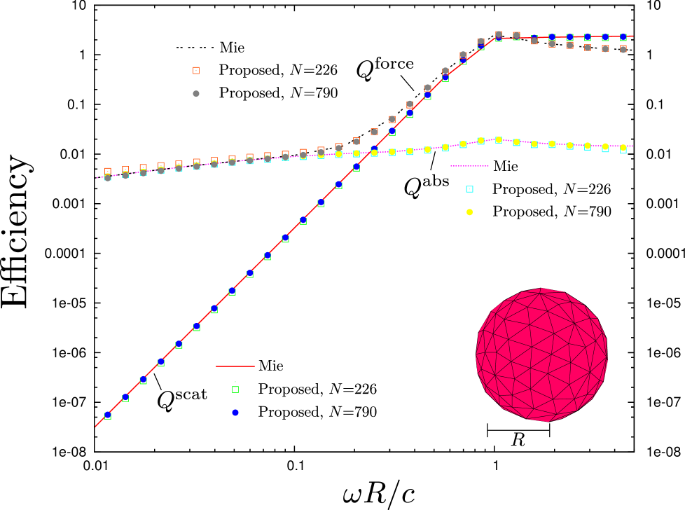
Figure 1 plots the efficiencies of scattering, absorption, and -directed force on a spherical nanoparticle of radius m, irradiated by a linearly-polarized -traveling plane wave with electric field The nanoparticle is composed of gold, modeled as a lossy dielectric with frequency-dependent permittivity
| (33) |
with rad / sec. Solid lines indicate the results of Mie theory [8], while squares (circles) indicate data points obtained using the method proposed in this paper using RWG basis functions for a sphere discretized into =226 (=790) trianglular panels. (The figure inset shows the =226 mesh.) The absorption and scattering cross sections are obtained by dividing the total absorbed and scattered power by the incident power flux, , where for a plane wave in vacuum and are computed using equations (10) and (14). The force cross section is obtained by dividing the total -directed force on the particle by the incident momentum flux, , where is computed using equation (22) and for a plane wave in vacuum. Efficiencies are obtained from cross sections by dividing by the geometrical cross section presented by the particle,
On the scale of this graph, errors due to finite mesh sizes are discernible only at the highest and lowest frequencies. The former are just the usual finite-mesh inaccuracies that arise in all BEM schemes when the wavelength of light is comparable to or smaller than the panel sizes. On the other hand, finite-mesh errors at low frequencies in quantities such as the force arise because the stress-tensor integral over the body surface implicit in the VMVP formula (22) exhibits, at low frequencies, large cancellations from different regions of the body surface that require fine meshing to resolve accurately.
There is of course no torque on a homogeneous spherical body irradiated by a plane wave. However, a nonzero torque may develop when the incident field is a finite-width laser beam whose center is displaced from the sphere center, and this situation may be studied numerically using a generalized Mie technique that allows arbitrary incident fields [47], with the torque computed by integrating the Maxwell stress tensor over a bounding surface. We have confirmed that the results of this procedure agree with results predicted by our formula (28) for the torque on a homogeneous sphere irradiated by an off-center laser beam.
IV-B Force and Torque on a Chiral Nanoparticle in a Circularly-Polarized Field
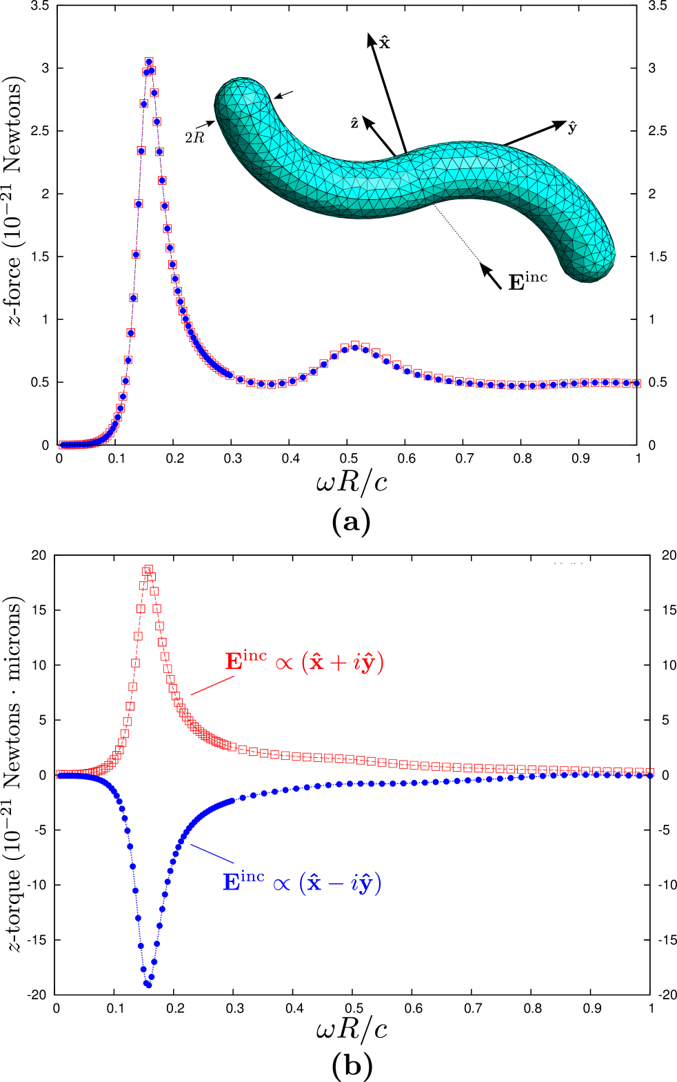
We next consider a chiral nanoparticle illuminated by a circularly-polarized plane wave. The particle is depicted in the inset of Figure 2(a); it is constructed from two quarter-length sections of a torus of {inner, outer} radii (here m) with one section rotated through degrees and both ends capped with hemispherical endcaps. The particle is composed of gold with permittivity given by equation (33). The particle is illuminated from below by a plane wave traveling in the positive direction and either left- or right-circular polarization, i.e. we have
with and V/m. Figures 2(a) and 2(b) respectively plot the force and torque on the particle as a function of frequency for both right-circularly polarized incident fields (blue circles) and left-circularly polarized incident fields (red squares). The force on the particle is the same for the two incident polarizations, while the torque changes sign when the incident polarization is reversed.
IV-C Frequency-Dependent Direction of Rotation on a Pair of Chiral Nanoparticles in a Linearly-Polarized Field
In the previous two examples—which involved isolated nanoparticles—the PFTs could in principle have been computed by the standard technique of integrating the PV or MST over a distant bounding surface surrounding the object, in which case the computation would involve only far fields and could have been performed without great difficulty using existing methods.
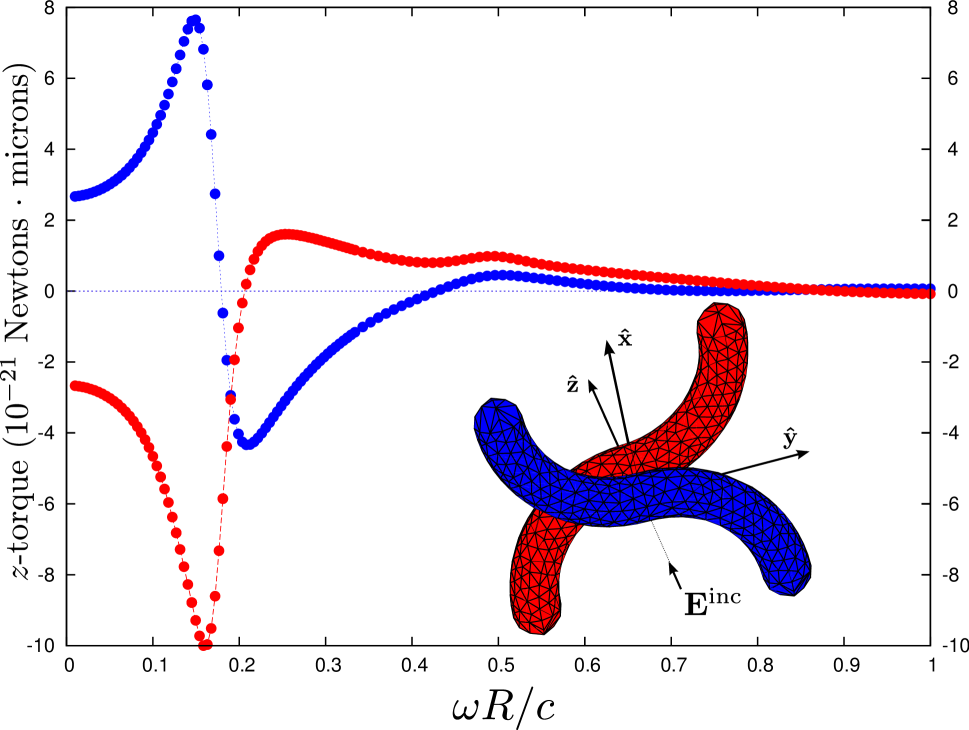
The method we propose in this paper really comes into its own for geometries involving two or more closely separated bodies for which we wish separately to resolve the PFTs. In such cases, any bounding surface surrounding only one of the bodies in question must unavoidably lie close to both bodies, and the stress-tensor integral over that surface will be particularly cumbersome, whereas the technique proposed in this paper is straightforward. An example of such a geometry is provided by pairing the chiral gold nanoparticle of the previous section with a partner gold nanoparticle of opposite chirality, separated by a surface-surface separation m (equal to the inner particle radius), and irradating the pair from below with a linearly, not circularly, polarized plane wave, Figure 3 plots the torque on each particle, with the blue (red) data points corresponding to the lower (upper) particle. Now not only the magnitudes but also the signs of the torques on the two particles are frequency-dependent, with the particles either co-rotating, counter-rotating, or not rotating depending on the frequency.
V Summary and Outlook
In this paper we derived concise and computationally efficient new formulas for the power, force, and torque on material bodies in classical scattering problems. These formulas may be viewed as the classical analogues of the “fluctuating-surface-current” formulas for Casimir forces and other fluctuation phenomena [39, 40, 41], and they may be derived and understood on the basis of at least two complementary physical pictures. We validated our new formulas by confirming that they reproduce analytical results for spheres, then used them to compute optical forces and torques in complex geometries that would be inconvenient to address using other methods.
In Section II we noted that our formula (16) for the total power had the advantage of manifest non-negativity, which follows from the negative semidefiniteness of the BEM matrix [41]. A similar statement holds for the alternative [] scattered power formula, equation (38). However, at present we are unaware of any demonstration that our our formulas (10) and (14) share this manifest non-negativity property. It would be of interest to prove that these expressions for non-negative physical quantities are in fact provably non-negative—or to derive alternative expressions that are.
In closing, we emphasize that all formulas derived in this paper are implemented in scuff-em, a free, open-source software implementation of the BEM in the EFIE and PMCHW formulations [48].
Acknowledgments
This work was supported in part by the Defense Advanced Research Projects Agency (DARPA) under grant N66001-09-1-2070-DOD, by the Army Research Office through the Institute for Soldier Nanotechnologies (ISN) under grant W911NF-07-D-0004, and by the AFOSR Multidisciplinary Research Program of the University Research Initiative (MURI) for Complex and Robust On-chip Nanophotonics under grant FA9550-09-1-0704.
Appendix A Equivalence-principle interpretation of power formulas
Equations (10) and (15) for the absorbed and total power were derived in Section II by integrating the Poynting vector over a bounding surface to compute energy flow into and out of a spatial volume. It is interesting to note that precisely the same formulas may be derived on the basis of an alternative picture in which the principle of equivalence [9, 49] is invoked to eliminate the material body, with questions of energy transfer recast as questions of work done on currents by fields or vice versa (work done on fields by currents). In addition to providing an appealing physical picture that complements the viewpoint of Section II, this approach has the advantage of furnishing a new VMVP formula for the scattered power which, though less computationally efficient than equation (14), avoids the numerical inaccuracies that befall that formula in cases where the extinction is dominated by absorption.
[Similar procedures for computing absorbed or scattered powers by evaluating the work done on currents by fields—or vice versa—were recently employed in Ref. 50 in the context of cloaking bandwidth studies. A distinction is that, whereas there the currents were physical volume currents on which the work done has immediate physical relevance, here the currents are effective—that is, fictitious—surface currents. This renders the corresponding physical interpretation somewhat more subtle, although the mathematical equivalence between the calculated work and the physical power is no less exact here than there.]
For simplicity we consider the case of a single compact homogeneous material body embedded in a homogeneous exterior medium and irradiated by an incident field whose sources lie in the exterior medium. A standard approach to formulating surface-integral equations is to solve for surface currents by demanding that the scattered fields they radiate satisfy the boundary conditions at all media interfaces [42]. The equivalence-principle approach (see, for instance, Figure 3-9[b] of Ref. 9) traverses an alternative logical sequence to arrive at the same surface-integral equations. In this picture, (a) the material object is absent, and hence all space is permeated simply by vacuum; (b) a distribution of electric and magnetic currents, created and sustained by unspecified means, exists throughout the two-dimensional region of space that would be occupied by the object surface if it were present (we will refer to this region as the “object surface” even though no object is present) and flows tangentially to that surface. (c) The total electromagnetic field everywhere in space is the sum of the incident field plus the field radiated by these currents (the “scattered” field). The scattered field at any point—including points in the interior of the region that would be occupied by the object if it were present (the “object volume”)—is computed by convolving the surface-current distribution with the dyadic Green’s functions (DGFs) for the exterior medium. (d) The total fields computed in this way turn out to yield (i) exactly zero for points inside the object volume, (ii) exactly the correct total fields for points outside the object volume, (iii) exactly one-half the correct total fields for points on the object surface [49].
In this picture, there is no absorbing medium anywhere in space, so there can be no volume power absorption. Instead, the absorbed, total, and scattered power are computed by considering the work done on the surface currents by the fields, to wit:
-
•
the absorbed power is equal to the work done on the surface currents by the total fields:
(34) -
•
the total power (extinction) is equal to the work done on the surface currents by the incident fields:
(35) -
•
the scattered power is equal to the work done by the surface currents (or by the unspecified mechanism which sustains them) on the scattered fields:
(36) (The minus sign arises because we are considering work done by currents on fields, not the other way around as usual).
Inserting equations (2) and (4) into equations (34) and (35) and evaluating the integrals over basis functions immediately recovers equations (10) and (15).
On the other hand, the VMVP formula that arises from (36) differs from the VMVP formula (14) for the scattered power. To see this, note that the scattered fields on the object surface are obtained by convolving the surface currents with the DGFs for the exterior medium:
| (37) |
Here e.g. represents the electric field at a point due to a unit-strength pointlike source of magnetic current at (the “ext” designation indicates that these are the DGFs of the exterior medium), denotes convolution, and the factor of arises because we are evaluating the fields on the body surface [49]. Inserting (37) into (36), we have
where is the 66 DGF that enters equation (37). Finally, inserting the surface-current expansions (2) and evaluating the integrals over basis functions yields a VMVP expression for the scattered power:
| (38) |
where, as in Section II, is the vector of surface-current expansion coefficients and the elements of the matrix are the interactions of the basis functions mediated by :
| (39) |
with
| (40) |
for {E,M}. Like equation (16), equation (38) has the advantage of being a manifestly nonnegative expression for the physically nonnegative scattered power; again this follows from the negative semidefiniteness of the matrix [41].
Computing the elements (40) entails no additional work beyond what is necessary to assemble the BEM system; indeed, the matrix in equation (3) is (in the PMCHW formulation) just the sum of plus its counterpart matrix involving the interactions of the basis functions mediated by the DGFs of the medium interior to the scattering object,
| (41) |
where is computed as in (39-40) with the replacement . Hence the work of computing the matrix in (38). is already done as soon as we have assembled the BEM system (3).
The VMVP formula for the scattered power derived in Section II [equation (14)] obtains the scattered power as the difference between the total power (extinction) and the absorbed power. In cases where the total power is dominated by absorption—such as for the gold sphere of Figure 1 at low frequencies—this amounts to computing a small number as the difference between two nearby large numbers and hence invites numerical inaccuracy. Equation (38) provides an alternative VMVP formula for the scattered power that avoids this difficulty. The drawback is that the matrix in (40) is dense, so the cost of evaluating (38) scales like instead of the scaling of (14).
By combining equations (16), (38), and (41), we obtain an alternative VMVP formula for the absorbed power:
| (42) |
Equation (42) complements (10) in the same way that Equation (38) complements (14): It is an formula for which the matrix elements are already computed by the usual BEM assembly process and hence require no additional work to calculate. However, because (10) does not suffer from the numerical instabilities that can afflict (14), we are unaware of any situation in which the use of (42) over (10) is worth the added computational cost.
Appendix B Overlap Integrals for RWG Basis Functions
In the main text we defined various types of overlap integrals involving pairs of basis functions. Here we present closed-form expressions for these integrals for the particular choice of RWG basis functions [38].
The overlap integrals are
where the integrations are over
Each RWG basis function is supported on a pair of flat triangular panels, and the overlap integrals have the structure
| (43) |
where the sum is over panels common to the supports of and (there may be 0, 1, or 2 such panels), is the panel area, according as is the positive or negative panel for basis function and is the length of the edge associated with . In what follows we give formulas for just the single-panel contributions .
If we fix the index in (43), then the sum on the RHS of that equation (a) receives nonvanishing contributions from two panels if , (b) receives nonvanishing contributions from one panel if is one of the four RWG basis functions that shares a common panel of support with , (c) vanishes otherwise. Thus each of the matrices has at most nonzero entries per row. ( has because the diagonal matrix element vanishes in that case.) The force and torque matrices defined by Equations (23) and (29) have nonzero entries per row.
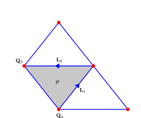
Our notational conventions for computing are summarized in Figure 4, which depicts a single panel common to the supports of two basis functions are the source/sink vertices for the two basis functions. We parameterize points in according to
in terms of which a general integral takes the form
The values of the RWG basis functions at are
with
(Note that for the case of diagonal matrix elements )
In what follows, will denote the outward-pointing surface normal to , and for a general vector we will use the shorthand notation to indicate the result of the cross-product with :
In principle, some of the results that follow could be simplified by using the relation and noting that may be expressed as a linear combination of and ; however, such simplifications depend on the precise orientation of the edges and are notationally cumbersome.
Power overlap integral
| (44) |
Force overlap integrals
Torque overlap integrals
In what follows we will work in a coordinate system with origin at , the point about which we figure the torque.
References
- [1] T. Eibert, “Some scattering results computed by surface-integral-equation and hybrid finite-element - boundary-integral techniques, accelerated by the multilevel fast multipole method,” Antennas and Propagation Magazine, IEEE, vol. 49, no. 2, pp. 61–69, 2007.
- [2] C. Uluisik, G. Cakir, M. Cakir, and L. Sevgi, “Radar cross section (rcs) modeling and simulation, part 1: a tutorial review of definitions, strategies, and canonical examples,” Antennas and Propagation Magazine, IEEE, vol. 50, no. 1, pp. 115–126, 2008.
- [3] W. L. Collett, C. A. Ventrice, and S. M. Mahajan, “Electromagnetic wave technique to determine radiation torque on micromachines driven by light,” Applied Physics Letters, vol. 82, no. 16, pp. 2730–2732, 2003. [Online]. Available: http://link.aip.org/link/?APL/82/2730/1
- [4] S. Makarov and S. Kulkarni, “Microwave radiation force and torque on a disk resonator excited by a circularly polarized plane wave,” Applied Physics Letters, vol. 84, no. 19, pp. 3795–3797, 2004.
- [5] A. Ashkin, “Acceleration and trapping of particles by radiation pressure,” Phys. Rev. Lett., vol. 24, pp. 156–159, Jan 1970. [Online]. Available: http://link.aps.org/doi/10.1103/PhysRevLett.24.156
- [6] F. V. Ignatovich and L. Novotny, “Experimental study of nanoparticle detection by optical gradient forces,” Review of Scientific Instruments, vol. 74, no. 12, pp. 5231–5235, 2003.
- [7] W. Sun, S. Pan, and Y. Jiang, “Computation of the optical trapping force on small particles illuminated with a focused light beam using a fdtd method,” Journal of Modern Optics, vol. 53, no. 18, pp. 2691–2700, 2006. [Online]. Available: http://www.tandfonline.com/doi/abs/10.1080/09500340600829077
- [8] C. F. Bohren and D. Huffman, Absorption and scattering of light by small particles, ser. Wiley science paperback series. Wiley, 1983. [Online]. Available: http://books.google.com/books?id=S1RCZ8BjgN0C
- [9] R. Harrington, Time-Harmonic Electromagnetic Fields, ser. IEEE Press series on electromagnétic wave theory. IEEE Press, 1961.
- [10] J. P. Barton, D. R. Alexander, and S. A. Schaub, “Internal and near-surface electromagnetic fields for a spherical particle irradiated by a focused laser beam,” Journal of Applied Physics, vol. 64, no. 4, pp. 1632–1639, 1988. [Online]. Available: http://link.aip.org/link/?JAP/64/1632/1
- [11] E. Almaas and I. Brevik, “Radiation forces on a micrometer-sized sphere in an evanescent field,” J. Opt. Soc. Am. B, vol. 12, no. 12, pp. 2429–2438, Dec 1995. [Online]. Available: http://josab.osa.org/abstract.cfm?URI=josab-12-12-2429
- [12] B. A. Kemp, T. M. Grzegorczyk, and J. A. Kong, “Optical momentum transfer to absorbing mie particles,” Phys. Rev. Lett., vol. 97, p. 133902, Sep 2006. [Online]. Available: http://link.aps.org/doi/10.1103/PhysRevLett.97.133902
- [13] T. M. Grzegorczyk, B. A. Kemp, and J. A. Kong, “Stable optical trapping based on optical binding forces,” Phys. Rev. Lett., vol. 96, p. 113903, Mar 2006. [Online]. Available: http://link.aps.org/doi/10.1103/PhysRevLett.96.113903
- [14] F. Xu, K. Ren, G. Gouesbet, X. Cai, and G. Gréhan, “Theoretical prediction of radiation pressure force exerted on a spheroid by an arbitrarily shaped beam,” Phys. Rev. E, vol. 75, p. 026613, Feb 2007. [Online]. Available: http://link.aps.org/doi/10.1103/PhysRevE.75.026613
- [15] K. M. Leung, “Optical bistability in the scattering and absorption of light from nonlinear microparticles,” Phys. Rev. A, vol. 33, pp. 2461–2464, Apr 1986. [Online]. Available: http://link.aps.org/doi/10.1103/PhysRevA.33.2461
- [16] L. Ng, B. Luff, M. Zervas, and J. Wilkinson, “Forces on a rayleigh particle in the cover region of a planar waveguide,” Lightwave Technology, Journal of, vol. 18, no. 3, pp. 388–400, 2000.
- [17] R. W. Going, B. L. Conover, and M. J. Escuti, “Electrostatic force and torque description of generalized spheroidal particles in optical landscapes,” pp. 703 826–703 826–12, 2008. [Online]. Available: + http://dx.doi.org/10.1117/12.795701
- [18] J. Chen, J. Ng, S. Liu, and Z. Lin, “Analytical calculation of axial optical force on a rayleigh particle illuminated by gaussian beams beyond the paraxial approximation,” Phys. Rev. E, vol. 80, p. 026607, Aug 2009. [Online]. Available: http://link.aps.org/doi/10.1103/PhysRevE.80.026607
- [19] Y.-X. Chen, “Radiation force of highly focused gaussian beams on a rayleigh metal particle,” in Image Analysis and Signal Processing (IASP), 2012 International Conference on, 2012, pp. 1–5.
- [20] R. Gussgard, T. Lindmo, and I. Brevik, “Calculation of the trapping force in a strongly focused laser beam,” J. Opt. Soc. Am. B, vol. 9, no. 10, pp. 1922–1930, Oct 1992. [Online]. Available: http://josab.osa.org/abstract.cfm?URI=josab-9-10-1922
- [21] R. C. Gauthier, “Ray optics model and numerical computations for the radiation pressure micromotor,” Applied Physics Letters, vol. 67, no. 16, pp. 2269–2271, 1995. [Online]. Available: http://link.aip.org/link/?APL/67/2269/1
- [22] M. Gu, D. Morrish, and P. C. Ke, “Enhancement of transverse trapping efficiency for a metallic particle using an obstructed laser beam,” Applied Physics Letters, vol. 77, no. 1, pp. 34–36, 2000. [Online]. Available: http://link.aip.org/link/?APL/77/34/1
- [23] T. A. Nieminen, V. L. Y. Loke, A. B. Stilgoe, G. Knöner, A. M. Brańczyk, N. R. Heckenberg, and H. Rubinsztein-Dunlop, “Optical tweezers computational toolbox,” Journal of Optics A: Pure and Applied Optics, vol. 9, no. 8, p. S196, 2007. [Online]. Available: http://stacks.iop.org/1464-4258/9/i=8/a=S12
- [24] L. Ling, F. Zhou, L. Huang, and Z.-Y. Li, “Optical forces on arbitrary shaped particles in optical tweezers,” Journal of Applied Physics, vol. 108, no. 7, pp. 073 110–073 110–8, 2010.
- [25] A. Taflove and K. Umashankar, “Review of fd-td numerical modeling of electromagnetic wave scattering and radar cross section,” Proceedings of the IEEE, vol. 77, no. 5, pp. 682–699, 1989.
- [26] R. Dewan, I. Vasilev, V. Jovanov, and D. Knipp, “Optical enhancement and losses of pyramid textured thin-film silicon solar cells,” Journal of Applied Physics, vol. 110, no. 1, p. 013101, 2011. [Online]. Available: http://link.aip.org/link/?JAP/110/013101/1
- [27] T. Cao, L. Zhang, and M. Cryan, “Optical forces in metal/dielectric/metal fishnet metamaterials in the visible wavelength regime,” Photonics Journal, IEEE, vol. 4, no. 5, pp. 1861–1869, 2012.
- [28] L. E. McNeil, A. R. Hanuska, and R. French, “Near-field scattering from red pigment particles: Absorption and spectral dependence,” Journal of Applied Physics, vol. 89, no. 3, pp. 1898–1906, 2001.
- [29] M. Barth and O. Benson, “Manipulation of dielectric particles using photonic crystal cavities,” Applied Physics Letters, vol. 89, no. 25, pp. 253 114–253 114–3, 2006.
- [30] G. Huda and J. Hastings, “Absorption modulation of plasmon resonant nanoparticles in the presence of an afm tip,” Selected Topics in Quantum Electronics, IEEE Journal of, vol. 19, no. 3, pp. 4 602 306–4 602 306, 2013.
- [31] H.-R. Chuang, “Human operator coupling effects on radiation characteristics of a portable communication dipole antenna,” Antennas and Propagation, IEEE Transactions on, vol. 42, no. 4, pp. 556–560, 1994.
- [32] ——, “Numerical computation of fat layer effects on microwave near-field radiation to the abdomen of a full-scale human body model,” Microwave Theory and Techniques, IEEE Transactions on, vol. 45, no. 1, pp. 118–125, 1997.
- [33] W.-T. Chen and H.-R. Chuang, “Numerical computation of the em coupling between a circular loop antenna and a full-scale human-body model,” Microwave Theory and Techniques, IEEE Transactions on, vol. 46, no. 10, pp. 1516–1520, 1998.
- [34] O. Bottauscio, M. Chiampi, and L. Zilberti, “Boundary element solution of electromagnetic and bioheat equations for the simulation of sar and temperature increase in biological tissues,” Magnetics, IEEE Transactions on, vol. 48, no. 2, pp. 691–694, 2012.
- [35] A. M. Kern and O. J. F. Martin, “Surface integral formulation for 3d simulations of plasmonic and high permittivity nanostructures,” J. Opt. Soc. Am. A, vol. 26, no. 4, pp. 732–740, Apr 2009. [Online]. Available: http://josaa.osa.org/abstract.cfm?URI=josaa-26-4-732
- [36] J. J. Xiao and C. T. Chan, “Calculation of the optical force on an infinite cylinder with arbitrary cross section by the boundary element method,” J. Opt. Soc. Am. B, vol. 25, no. 9, pp. 1553–1561, Sep 2008. [Online]. Available: http://josab.osa.org/abstract.cfm?URI=josab-25-9-1553
- [37] A. Kern and O. J. F. Martin, “Pitfalls in the determination of optical cross sections from surface integral equation simulations,” Antennas and Propagation, IEEE Transactions on, vol. 58, no. 6, pp. 2158–2161, 2010.
- [38] S. M. Rao, D. R. Wilton, and A. W. Glisson, IEEE Trans. Antennas Propagat., vol. AP-30, p. 409, 1982.
- [39] M. Reid, A. Rodriguez, and S. Johnson, “Fluctuation-induced phenomena in nanoscale systems: Harnessing the power of noise,” Proceedings of the IEEE, vol. 101, no. 2, pp. 531–545, 2013.
- [40] M. T. Homer Reid, J. White, and S. G. Johnson, “Fluctuating Surface Currents: A New Algorithm for Efficient Prediction of Casimir Interactions among Arbitrary Materials in Arbitrary Geometries. I. Theory,” ArXiv e-prints, Feb. 2012.
- [41] A. W. Rodriguez, M. T. Homer Reid, and S. G. Johnson, “Fluctuating surface-current formulation of radiative heat transfer: theory and applications,” ArXiv e-prints, Apr. 2013.
- [42] L. N. Medgyesi-Mitschang, J. M. Putnam, and M. B. Gedera, “Generalized method of moments for three-dimensional penetrable scatterers,” J. Opt. Soc. Am. A, vol. 11, no. 4, pp. 1383–1398, Apr 1994. [Online]. Available: http://josaa.osa.org/abstract.cfm?URI=josaa-11-4-1383
- [43] P. Yla-Oijala and M. Taskinen, “Well-conditioned Müller formulation for electromagnetic scattering by dielectric objects,” Antennas and Propagation, IEEE Transactions on, vol. 53, no. 10, pp. 3316–3323, 2005.
- [44] R. F. Harrington, Field Computation by Moment Methods. Wiley-IEEE Press, 1993.
- [45] L. Trefethen and D. Bau, Numerical Linear Algebra, ser. Miscellaneous Bks. Cambridge University Press, 1997. [Online]. Available: http://books.google.com/books?id=bj-Lu6zjWbEC
- [46] J. D. Jackson, Classical Electrodynamics, 3rd ed. John Wiley & Sons, 1999.
- [47] http://homerreid.com/libSphericalScattering.
- [48] http://homerreid.com/scuff-EM.
- [49] Y. Chen, “A mathematical formulation of the equivalence principle,” Microwave Theory and Techniques, IEEE Transactions on, vol. 37, no. 10, pp. 1576–1581, 1989.
- [50] H. Hashemi, C.-W. Qiu, A. P. McCauley, J. D. Joannopoulos, and S. G. Johnson, “Diameter-bandwidth product limitation of isolated-object cloaking,” Phys. Rev. A, vol. 86, p. 013804, Jul 2012. [Online]. Available: http://link.aps.org/doi/10.1103/PhysRevA.86.013804