Efficient separation of the orbital angular momentum eigenstates of light
Mohammad Mirhosseini1,∗, Mehul Malik1,2, Zhimin Shi1,3, and Robert W. Boyd1,4
1The Institute of Optics, University of Rochester,
Rochester, New York 14627 USA
2Institute for Quantum Optics and Quantum Information (IQOQI), Austrian Academy of Sciences, Boltzmanngasse 3, A-1090 Vienna, Austria.
3Department of Physics, University of South Florida, Tampa, FL 33620, USA
4Department of Physics, University of Ottawa, Ottawa, ON K1N 6N5 Canada
∗mirhosse@optics.rochester.edu
Orbital angular momentum (OAM) of light is an attractive degree of freedom for fundamentals studies in quantum mechanics. In addition, the discrete unbounded state-space of OAM has been used to enhance classical and quantum communications. Unambiguous measurement of OAM is a key part of all such experiments. However, state-of-the-art methods for separating single photons carrying a large number of different OAM values are limited to a theoretical separation efficiency of about 77 percent. Here we demonstrate a method which uses a series of unitary optical transformations to enable the measurement of light s OAM with an experimental separation efficiency of more than 92 percent. Further, we demonstrate the separation of modes in the angular position basis, which is mutually unbiased with respect to the OAM basis. The high degree of certainty achieved by our method makes it particularly attractive for enhancing the information capacity of multi-level quantum cryptography systems.
Introduction
It has long been known that the polarization state of the optical field can be associated with the spin angular momentum [1, 2]. In 1992, it was shown by Allen et al. that in the paraxial regime, a vortex phase structure of a circularly symmetric beam corresponds to units of OAM [3]. Since then, OAM of light has been found as a useful tool in a variety of applications [4, 5, 6, 7, 8]. OAM modes with different values form a large orthonormal set of functions that can be used to encode information. It has been suggested that OAM encoding can be used alongside polarization to increase the channel capacity of communication systems [9, 10]. Additionally, the use of a multi-level encoding basis such as the OAM basis can increase the tolerance of QKD systems to eavesdropping [11]. Clearly, applications of this sort will require a method of sorting photons carrying OAM with a high separation efficiency, which is a measure for the degree of separation of the sorted OAM modes, as well as a high power transmission efficiency, which is an indicator of the optical throughput of the system in presence of loss. Although the two eigenstates of polarization can be separated easily by using a polarizing beam splitter, separation of OAM eigenstates has proven to be challenging until recently [14, 12, 13].
A forked hologram can be used to add or remove spiral phase structures in its diffraction orders [15]. Similarly, a q-plate can be used to create OAM modes by utilizing the spin-orbit coupling in inhomogeneous anisotropic media [16, 17, 18]. Such elements can be used for measuring the OAM content of a beam by performing a series of projection measurements [4, 8]. In this method, an input laser beam illuminates multiple forked holograms or q-plates with different quantum numbers and the transmitted light is collected by multiple single mode fibers which correspond to different OAM values. If an OAM beam with quantum number enters this system, its phase structure will only be corrected by the element that adds a phase of and a detection happens at the corresponding detector. This method can be used to distinguish between different OAM modes with high accuracy [19, 8]. However, projection measurements are always limited by a success rate of , where is the number of the OAM modes involved in the experiment. This property makes this method unsuitable for single photon experiments that involve a large number of OAM modes.
More sophisticated holograms designs can be made to achieve separation of several OAM modes using a single phase-screen [15]. However, none of these designs have proven to be efficient enough for separation of OAM modes at the single-photon level. Similarly, the results achieved using thick holograms have been only marginally better [20]. Leach et al. have presented a technique for separating OAM modes at the single-photon level based on using a Mach-Zehdner interferometer with a Dove prism in each arm [14]. This setup allows the separation of single photons based on their parity. Although in principle this method works with a 100% efficiency, separating modes requires cascaded interferometers. The challenge in designing and aligning such a complicated system considerably limits its applications.
Berkhout et al. have recently demonstrated a very successful method for sorting OAM modes that employs a Cartesian to log-polar transformation [12]. Under this transformation, the azimuthal phase profile of an OAM mode is mapped to a tilted planar wavefront. As a result, a set of OAM modes with different quantum numbers is converted to a set of truncated plane waves with wavefront tilts which are proportional to . These plane waves are then separated by a single lens. This method of sorting OAM modes is exclusively based on unitary transformations and in theory can achieve a power transmission efficiency of unity. However, the degree of separation of two neighboring OAM modes is limited by diffraction due to the finite size of the unwrapped modes.
In this work we experimentally implement an architecture that combines log-polar coordinate mapping with refractive beam copying to substantially enhance the separation of the transformed OAM modes. Furthermore, we use a variation of this method for sorting angular(ANG) modes, which form an unbiased basis set with respect to the OAM modes. We achieve a separation efficiency of for a set of 25 OAM modes and for the corresponding 25 ANG modes, which are equivalent to mutual information values of 4.18 and 4.16 bits per detected photons respectively.
Results
Mode overlap in log-polar coordinate mapping. To achieve the coordinate transformation, the beam’s amplitude is multiplied by a phase-only transmittance function . The amplitude of the field in the conjugate Fourier plane can be calculated by using the stationary phase approximation, resulting in a geometrical map between the input and output planes [21]. This mapping is accompanied by an undesired varying phase term. This phase distortion arises from variations in the optical path length and can be removed by introducing a second phase plate at the Fourier plane of the input plane. A coordinate mapping of and can be achieved using the following phase elements [23, 12]
| (1) | ||||
| (2) |
It is easy to check that the azimuthal phase profile of an OAM mode is mapped to a tilted planar wavefront under this transformation. The set of plane waves resulting from the transformation of OAM modes with different quantum numbers are then separated by a single lens positioned in the plane.
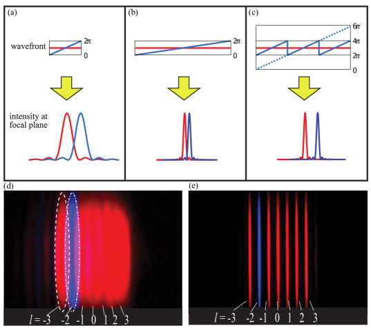
Fig. 1(a) demonstrate the situation where the plane waves resulting from the transformation of two neighboring OAM modes are focused to diffraction-limited spots which are partially overlapping. In Ref. [13], the authors have measured the fraction of intensity overlap between the neighboring modes to be about 20 percent (See Fig. 1(e)). This is in fact an inherent limitation of this method and cannot be avoided by magnifying the transformed plane waves. Magnifying a plane wave results in a decrease in the tilt angle across its wavefront. Such magnified plane waves can be focused to narrower spots, but the spacing between the spots gets reduced accordingly such that the degree of overlap between them remains constant (Fig. 1(b)).
Motivated by a suggestion of Berkhout et al [12], we recently investigated the effects of a beam-copying device on the degree of separation of transformed OAM modes [24]. Our previous simulation work along with the preliminary experimental results suggested that the use of such a device may dramatically reduce mode overlap. In the present paper, we describe the full implementation of this idea. This method works by mapping each OAM mode to multiple copies of the tilted planar wavefronts. In this situation the width of the transformed beam has been increased, while the angle of the tilt across it remains constant. Note that the periodic phase jumps between the neighboring copies of the truncated plane waves are equal to integer multiples of , so the resulting larger beam will have a smooth wavefront. These converted modes can now be focused to a series of spots which have the same spacing as before but are much narrower in width [24] (Fig. 1(c) and Fig. 1(e)).
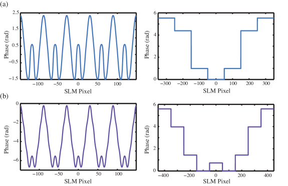
Refractive beam copying. We have used a periodic phase-only hologram known as a fan-out element to make multiple coherent copies of the unwrapped OAM modes. The phase structure of such a device can be described as [26]
| (3) |
where is the number of copies of the beam, is the angular separation between them, and is the transverse dimension along which the copies are made (See Fig. 2 (a) and (b)). Here, and are relative phase and intensity parameters associated with different diffraction orders (See Supplementary Note 1 and Supplementary Table S1). These parameters can be optimized using numerical or analytical methods to uniformly distribute more than 99 percent of the incident light between the copies [26, 25].
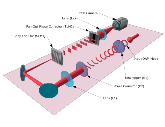
Sorting OAM modes. In our experiment, we generate OAM modes using a spatial light modulator (SLM) and a 4f system of lenses [27]. As shown in Fig. 3 the OAM beam then propagates through the refractive elements which perform the log-polar coordinate transformation [13]. A fan-out element realized on SLM1 generates multiple copies of this truncated plane wave mode. For clarity Fig. 3 shows a fan-out element only creating 3 copies. However, we have used a fan-out design which creates 7 copies of the beam [26] (See Supplementary Fig. S1 and Supplementary Table S1). SLM2 is used to correct the relative phase between these copies at the Fourier plane of the fan-out element. The holograms for the fan-out element and the corresponding phase corrector are shown in Fig. 2 (a). Finally, a lens is used to focus the extended plane-wave to a spot, where a charge-coupled-device (CCD) camera measures its intensity profile.
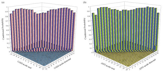
We have measured OAM modes with quantum numbers of -12 to 12 using our method. We divide the area on the CCD into 25 non-overlapping adjacent spatial bins. Each of the bins corresponds to the central position of the spot resulting from the transformation of an OAM mode. By sending a known OAM mode through the system and measuring the power in all 25 bins, we have constructed the conditional probability matrix for detection of all 25 OAM modes (Fig. 4(a)). The average probability of correctly detecting an OAM mode is calculated to be percent. This is slightly lower than the theoretical maximum of 97 percent [24] due to the non-ideal behavior of a phase-only fan-out element, undesired effects from pixelation of the SLMs, and small misalignments in the system. However, this is substantially higher than the maximum separation efficiency of 77 percent achieved by just the log-polar mapping method [12]. We have compared these two methods quantitatively in the Supplementary Note 2.
Another common measure of quantizing the separation efficiency of a mode sorter is the mutual information between the set of sent and detected modes. For the data presented here, the mutual information is calculated to be 4.18 bits per detected photon, as compared to the theoretical upper limit of 4.64 bits per detected photon for a set of 25 modes (See Supplementary Note 3 and Supplementary Fig. S2). It should be emphasized that these values are calculated for the detected photons and they exclude the technical loss in the experimental setup. The use of this metric can be justified considering the fact that the losses are caused by the limitations in technology and they are not inherent to our method. The refractive elements that perform the log-polar mapping have a combined transmission efficiency of 85 percent [13]. The SLMs that realize the fan-out element and its phase corrector are each measured to have a diffraction efficiency of 42 percent (For a complete analysis of the effect of loss on the overall information capacity of the system, please see Supplementary Note 3).
QKD and angular modes. In order to guarantee security against eavesdropping in QKD, at least two mutually unbiased bases (MUBs) are required [28]. A MUB for OAM can be constructed from the superposition of OAM modes with equal weights and a relative phase [10, 24]:
| (4) |
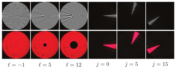
Here, an OAM mode is written as and is the maximum OAM quantum number which is used in forming the basis. Members of this MUB are referred to as the angular (ANG) modes, due to angular localization of their intensity patterns (Fig. 5). It is easy to check that if ANG modes are measured in the OAM basis, all the OAM modes in the range may be detected with equal probabilities. ANG modes with different indices are orthogonal in term of their amplitudes, however, the intensity profiles of these modes have side lobes around their central angular component which creates substantial overlap between any two neighboring modes (See Fig. 5). A detection scheme based on the intensity confinement of ANG mode has the rate of error of 23 percent [24].
Sorting ANG modes. An efficient method of sorting both OAM and ANG modes is needed to realize an OAM-based QKD system. Previous methods of sorting OAM modes are incapable of sorting ANG modes [10]. However, a variation of the sorting method described above can be used to sort these modes [24]. Since the unwrapped OAM and ANG modes are related via a Fourier transform in the horizontal direction, we can sort ANG modes by removing the Fourier-transforming lens L1 after the second refractive element R2. Instead the unwrapped mode is imaged directly into the fan-out element. We use a fan-out element creating 9 copies (See Supplementary Note 1 and Supplementary Table S1). The holograms for the fan-out element and the corresponding phase corrector are shown in Fig. 2(b). The ANG modes are transformed to a series of separated spots at the focal plane of the lens L2.
The conditional probability matrix for 25 ANG modes is shown in Fig. 4(b). The average probability for correct detection of an ANG mode in this set is measured to be percent. The mutual information calculated from the measured conditional probability matrix equals 4.16 bits per detected photon, demonstrating the capability of sorting ANG modes with approximately the same separation efficiency as that of the OAM modes.
In this experiment, we have demonstrated a method for unambiguous discrimination of OAM modes. A complex optical transformation is used along with a refractive beam-copying method to map OAM modes to a set of extended plane waves which are then separated using a lens. Using our technique, we have measured a channel capacity of 4.18 bits per detected photon for a free-space communication system using 25 OAM modes. Additionally, we have demonstrated a comparable ability to efficiently sort 25 modes in the mutually unbiased basis of angular position. Our technique will enable the development of high-dimensional QKD systems with record channel capacities of more than 4 bits per detected photon. In addition, this method will allow for detailed studies of fundamental quantum phenomena in the unbounded state-space of orbital angular momentum.
Methods
Equipments and experimental techniques. A Helium Neon laser beam (632.8 nm) is spatially filtered using a single-mode fiber. The output of the fiber is collimated and illuminates a high-definition Holoeye PLUTO phase-only SLM. The OAM and ANG modes are created using computer generated holograms [27] (See Supplementary Note 4). An aperture in used in between a 4f system to pick up the first order diffracted beam. Machined PMMA (Poly methyl methacrylate) refractive elements mounted in a Thorlabs cage system are used for log-polar coordinate mapping [13]. Two Holoeye PLUTO phase-only SLMs are used for realizing the hologram for the fan-out element and its corresponding phase-correcting element. A telescope system is used for coherent imaging of ANG modes to the fan-out hologram. Single images were obtained on a Canon 5D mark III CCD camera providing 14 bits of dynamic range. A Semrock 632.8 nm MaxLine filter is used in front of the camera to block stray light. An exposure time of 125 s is chosen to further the suppress background light.
References
- [1] Poynting, J. H. The Wave Motion of a Revolving Shaft, and a Suggestion as to the Angular Momentum in a Beam of Circularly Polarised Light. Proc. R. Soc. London, Ser. A 82, 560–567 (1909).
- [2] Beth, R. Mechanical Detection and Measurement of the Angular Momentum of Light. Phys. Rev. 50, 115–125 (1936).
- [3] Allen, L., Beijersbergen, M. W., Spreeuw, R. & Woerdman, J. P. Orbital angular momentum of light and the transformation of Laguerre-Gaussian laser modes. Phys. Rev. A 45, 8185–8189 (1992).
- [4] Mair, A., Vaziri, A., Weihs, G., & Zeilinger, A. Entanglement of the orbital angular momentum states of photons. Nature 412, 313–316 (2001).
- [5] Molina-Terriza, G., Torres, J. P. & Torner, L. Twisted photons. Nat Phys. 3, 305–310 (2007).
- [6] Malik, M., Mirhosseini, M., Lavery, M. P. J., Leach, J., Padgett, M. J. & Boyd, R. W. Direct Measurement of Quantum State Rotations. Preprint at http://arxiv.org/abs/1306.0619 (2013).
- [7] Barreiro, J. T., Wei, T.-C. & Kwiat, P. G. Beating the channel capacity limit for linear photonic superdense coding. Nature Photon. 4, 282–286 (2008).
- [8] Wang, J. et al. Terabit free-space data transmission employing orbital angular momentum multiplexing. Nature Photon. 6, 488–496 (2012).
- [9] Boyd R. W. et al. Quantum key distribution in a high-dimensional state space: exploiting the transverse degree of freedom of the photon.. Proc. SPIE 7948, Advances in Photonics of Quantum Computing, Memory, and Communication IV 79480L (2011).
- [10] Malik, M. et al. Influence of atmospheric turbulence on optical communications using orbital angular momentum for encoding. Opt. Express 20, 13195–13200 (2012).
- [11] Bourennane, M., Karlsson, A., Björk, G. Quantum key distribution using multilevel encoding. Phys. Rev. A 64, 012306 (2001).
- [12] Berkhout, G., Lavery, M., Courtial, J., Beijersbergen, M. & Padgett, M. Efficient Sorting of Orbital Angular Momentum States of Light. Phys. Rev. Lett. 105, 153601 (2010).
- [13] Lavery, M. P. J. et al. Refractive elements for the measurement of the orbital angular momentum of a single photon. Opt. Express 20, 2110–2115 (2012).
- [14] Leach, J. et al. Interferometric Methods to Measure Orbital and Spin, or the Total Angular Momentum of a Single Photon. Phys. Rev. Lett. 92, 013601 (2004).
- [15] Gibson, G. et al. Free-space information transfer using light beams carrying orbital angular momentum. Opt. Express 12, 5448-5456 (2004).
- [16] Marrucci, L., Manzo, C. & Paparo, D. Optical Spin-to-Orbital Angular Momentum Conversion in Inhomogeneous Anisotropic Media. Phys. Rev. Lett. 96, 163905 (2006).
- [17] Nagali, E. et al. Quantum Information Transfer from Spin to Orbital Angular Momentum of Photons. Phys. Rev. Lett. 103, 013601 (2009).
- [18] Marrucci, L., et al. Spin-to-orbital conversion of the angular momentum of light and its classical and quantum applications. J. Opt. 13, 064001 (2011).
- [19] Karimi, E., Piccirillo, B., Nagali, E., Marrucci, L. & Santamato, E. Efficient generation and sorting of orbital angular momentum eigenmodes of light by thermally tuned q-plates. Appl. Phys. Lett. 94, 231124 (2009).
- [20] Gruneisen, M. T., Dymale, R. C., Stoltenberg, K. E. & Steinhoff, N. Optical vortex discrimination with a transmission volume hologram. New J. Phys. 13, 0830309 (2011).
- [21] Bryngdahl, O. Geometrical transformations in optics. J. Opt. Soc. Am. A 64, 1092–1099 (1974).
- [22] Bryngdahl, O. Optical Map Transformations. Opt. Commun. 10, 164–168 (1974).
- [23] Saito, Y., Komatsu, S.-I. & Ohzu, H. Scale and rotation invariant real time optical correlator using computer generated hologram. Opt. Commun. 47, 8–11 (1983).
- [24] O’Sullivan, M. N., Mirhosseini, M., Malik, M. & Boyd, R. W. Near-perfect sorting of orbital angular momentum and angular position states of light. Opt. Express 20, 24444–24449 (2012).
- [25] Prongue, D., Herzig, H. P., Dandliker, R. & Gale, M. T. Optimized kinoform structures for highly efficient fan-out elements. Appl. Opt. 31, 5706–5711 (1992).
- [26] Romero, L. A. & Dickey, F. M. Theory of optimal beam splitting by phase gratings. I. One-dimensional gratings. J. Opt. Soc. Am. A 24, 2280–2295 (2007).
- [27] Arrizon, V., Ruiz, U., Carrada, R., Gonzalez, L. A. Pixelated phase computer holograms for the accurate encoding of scalar complex fields. J. Opt. Soc. Am. A 24, 3500–3507 (2007).
- [28] Bennett, C. H. & Brassard, G. Quantum cryptography: public key distribution and coin tossing. Proc. IEEE Int. Conf. 175–179 (1984).
Acknowledgements
The authors would like to thank M. O’Sullivan, B. Rodenburg, M. Lavery, Dr. E. Karimi, Dr. M. Padgett, and Dr. D. Gauthier for helpful discussions. This work was supported by the DARPA InPho Program. In addition, M. Malik acknowledges funding from the European Commission through a Marie Curie Fellowship, and RWB acknowledges support from the Canada Excellence Research Chairs program.
Author Contributions
M.Mirhosseini designed the experiment. M. Mirhosseini, M. Malik and Z. S. performed the experiment and analyzed data. R. W. B. supervised the project. M.Mirhosseini wrote the manuscript with contributions from all authors.
Additional information
The authors declare no competing financial interests. Reprints and permission information are available online at http://npg.nature.com/reprintsandpermissions/. Correspondence and requests for materials should be addressed to M. Mirhosseini.