LIGHT TRANSMISSION THROUGH A TRIANGULAR AIR GAP
Abstract
Due to the recent interest in studying propagation of light through triangular air gaps, we calculate, by using the analogy between optics and quantum mechanics and the multiple step technique, the transmissivity through a triangular air gap surrounded by an homogeneous dielectric medium. The new formula is then compared with the formula used in literature. Starting from the qualitative and quantitative differences between these formulas, we propose optical experiments to test our theoretical results.
I. INTRODUCTION
Propagation of light through rectangular air gaps situated between homogeneous media is surely one of the most intriguing phenomenon of optics[1, 2, 3]. Although studied for hundred of years[4, 5, 6], it still represents matter of discussion and challenge for theoretical and experimental investigations[7, 8, 9, 10, 11, 12, 13, 14, 15]. For a plane, time-harmonic, electromagnetic wave moving along the -axis, the transmissivity through a rectangular air gap, surrounded by an homogeneous dielectric whose properties are constant throughout each plane perpendicular to a fixed direction , is given by[13, 16, 17]
| (1) |
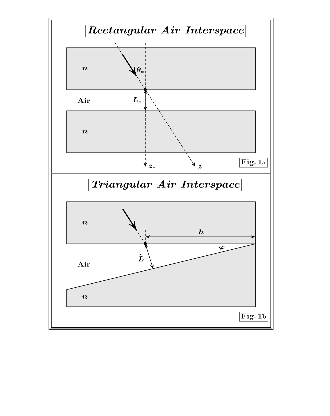
The upper index and respectively refer to waves linearly polarized with its electric and magnetic vector perpendicular to the - incidence plane, the so-called transverse electric (TE) and magnetic (TM) waves[1]. The incidence angle is the angle between the beam motion ( axis) and the stratification direction ( axis), is the wave number, is the distance between the dielectric blocks of refractive index ,
The geometric layout is drawn in Fig. 1a. For an incidence angle which tends to the critical angle , the transmissivity is given by
| (2) |
In this case, for no light is transmitted in the second dielectric block. Decreasing the value of up to several wavelengths, waves pass through the air interspace and light is transmitted in the second dielectric block. Due to the fact that varying the thickness of an air gap with precision is a very hard task, it has been proposed to study the transmission through a triangular air gap[18]. This allows, by changing the incidence point of the light on the first dielectric/air interface, , to study the propagation through air gaps of different thickness, see Fig. 1b. Observing that the transmission probability is highly sensitive to the air gap between the dielectric blocks, coherence phenomena can be only seen for very small angles, i.e. . The distance between the dielectric blocks, , can be then approximated by and we can use for the transmissivity through a triangular air gap the following formula[13],
| (3) |
For , the incident beam is in general divided between two secondary beams. Nevertheless, there is a situation in which we have only the transmitted beam. The phenomenon of total transmission happens when is an integer multiple of . For , the triangular air gap acts as a frequency filter and only wavelengths of the order of are transmitted from the first to the second dielectric block.
The formulas used for the transmission of light through three layers, see Eq. (1), are classical formulas. It is highly desirable to find a quantum analog. Starting from the analogy between optics[1, 2, 3] and quantum mechanics[19, 20] and by using the multiple step technique[21, 22, 23], we calculate the propagation of an electromagnetic wave through a triangular air gap. Then, for , we analyze the differences between the new formula and the approximated one given in Eq. (3) and used in litterature[13].
The paper is structured as follows. In section II, we discuss the analogies between light interaction upon the dielectric/air interface and the step potential in non relativistic quantum mechanics (NRQM). In section III, for the convenience of the reader, we briefly review the multiple step calculation[21, 22, 23, 24] which leads, for a rectangular air gap, to the transmission amplitude given in Eq. (1). In section IV, we consider -rotation of the second interface in the multiple step calculation and give the new transmission formula. In the final section, we draw our conclusions. In particular, we shall compare our formula with the formula used in literature, Eq. (3), and propose optical experiments for testing the new formula.
II. ANALOGY BETWEEN OPTICS AND QUANTUM MECHANICS
In this section, we present the connection between optical and quantum mechanics problems. In particular, we show how the NRQM formalism can be easily used to obtain the well-known Fresnel formulas for reflection and transmission of and polarized light. This connection will be fundamental for the calculation of the transmission probabilities done in the following sections.
Let us consider the plane as the incidence plane. The incident ray travels in the first dielectric block of refractive index along the -axis,
In terms of the new - axes, the incident wave number can be rewritten as follows
| (4) |
The dynamics of TE waves, which moving in the first dielectric block encounter the dielectric/air discontinuity , is governed by[1]
| (5) |
This equation, by taking the correspondence
exactly mimics the NRQM step potential dynamics[19]. This is obviously a mathematical analogy. The Maxwell and Schrödinger equations describe a different physics and such equations only coincide, in their mathematical description, for special cases. This correspondence is, for example, not exact for TM waves. As it will be shown later, for TM waves we obtain the Fresnel formulas by introducing a translation rule. The TE incident and reflected beams which move in the first dielectric block, , are represented by the wave function
where and are the wave number components of the beam which propagates in the first dielectric block. The transmitted beam which moves in the air gap, , is represented by
and are now the wave number components of the beam which propagates in the air gap. Being the discontinuity along the axis, the component of the wave number does not change passing from the dielectric to air, i.e. . This implies
| (6) |
From the matching conditions, and , we find[25]
| (7) |
The Fresnel formulas are immediately obtained from the previous amplitudes,
| (8) |
For , tends to zero and we have total reflection, . The reflection and transmission amplitudes for TM waves can be obtained by using the following translation rules,
| (9) |
For , the incident beam is, in general, partially reflected and transmitted with intensities
| (10) |
For a particular angle,
known as Brewster s angle[1, 2, 3], we have which implies and, consequently, the incident light is totally transmitted.
III. MULTIPLE STEP ANALYSIS FOR A RECTANGULAR AIR GAP
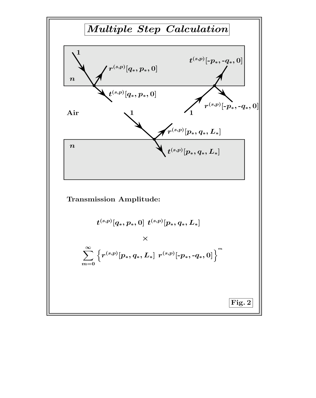
It was demonstrated in previous works[14, 15] that, the transmission and reflection amplitudes of a rectangular (air) interspace can be built up by successive application of the step analysis[24, 21, 22, 23]. As illustrated in Fig. 2, at the first dielectric/air surface, , the incident wave is divided in two plane waves. The transmitted wave with amplitude moves through the air gap and after touching the second air/dielectric surface, , will be transmitted with amplitude
This represents the first contribution to transmission through the rectangular air gap. The complete transmission amplitude is built up by considering the loop factor obtained by multiplying the amplitude of the reflected wave at the second air/dielectric surface by the one of the reflected wave at the first air/dielectric surface,
If overlaps dominate, a single beam is transmitted and to find the transmission amplitude we have to sum all coherent multiple contributions,
| (11) |
Let us first calculate the transmissivity for the case of TE waves. Observing that
| (12) | |||||
we have
| (13) |
A simple calculation shows that
| (14) |
and, consequently, we reproduce Eq. (1) for -polarized waves. In a similar way, observing that
| (15) |
and
| (16) |
we obtain Eq. (1) for TM waves.
IV. TRANSMISSION THROUGH A TRIANGULAR AIR GAP
For the first dielectric/air interface, the computation of the transmissivity through the triangular air gap follows the calculation done in the previous section. For the second discontinuity, we have to observe that the second dielectric block is now rotated, with respect to the original layout, by an angle
The transmission through a triangular air gap can be immediately obtained from Eq.(III. MULTIPLE STEP ANALYSIS FOR A RECTANGULAR AIR GAP), by substituting the first transmitted wave amplitude and the loop factor respectively by
with
We then find
| (17) |
Let us first discuss the case of TE waves and rewrite Eq. (17) as follows
| (18) | |||||
Observing that at the first discontinuity, , the transmissivity is obtained by multiplying by the factor , whereas at the second discontinuity, , the transmissivity is obtained by multiplying by , we have for the transmissivity through a triangular air gap
| (19) |
with
| (20) |
For TM waves, we find
| (21) |
with
| (22) |
V. CONCLUSIONS
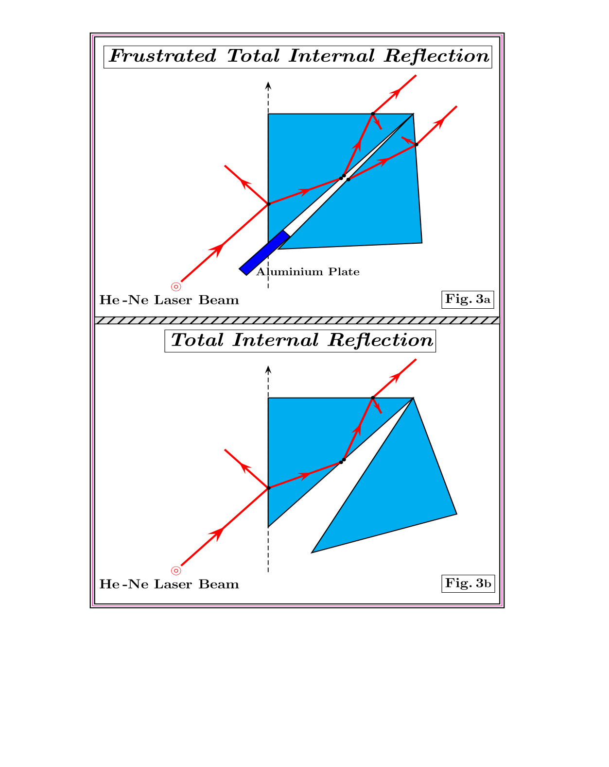
The major difficulty in positioning two parallel surfaces sufficiently close to each other to allow resonances phenomena or to frustrate total internal reflection is controlling their distance with accuracy and precision. To overcome this difficulty, it has been suggested a triangular configuration[13], see Fig. 3. This configuration was first investigated by using spectral lamps as light source[18] and recently by using a He-Ne laser beam[13].
Using the well known technique of the multiple step analysis[21, 22, 23] for rectangular air gaps[14, 15], we have proposed a new formula for the transmission through a dielectric/ar/dielectric triangular system,
| (23) |
These formulas have to be compared with the formulas used in literature and given in Eq.(3),
| (24) |
As observed in the introduction, the condition is a necessary condition to guarantee, in the case of diffusion, coherence and consequently resonance phenomena and, in the case of tunneling, frustrated total internal reflection, see Fig. 3a. In this case,
In looking for significant differences between the standard formula and the new formula proposed in this paper, we have to amplify the -term in . This can be done by increasing in the sine argument. To estimate for which values of the resonances obtained from the approximated formula given in Eq. (24) differ from the resonances calculated from the new formula given in Eq. (23), let us explicit the resonance conditions for each case
| (25) |
It is clear that the maximum shift between the resonances is obtained for
This implies, and consequently an incident point on the first interface, , of the order of . Another important quantity to be estimated is the distance between two successive resonances, . For wavelengths of the order of m, we find
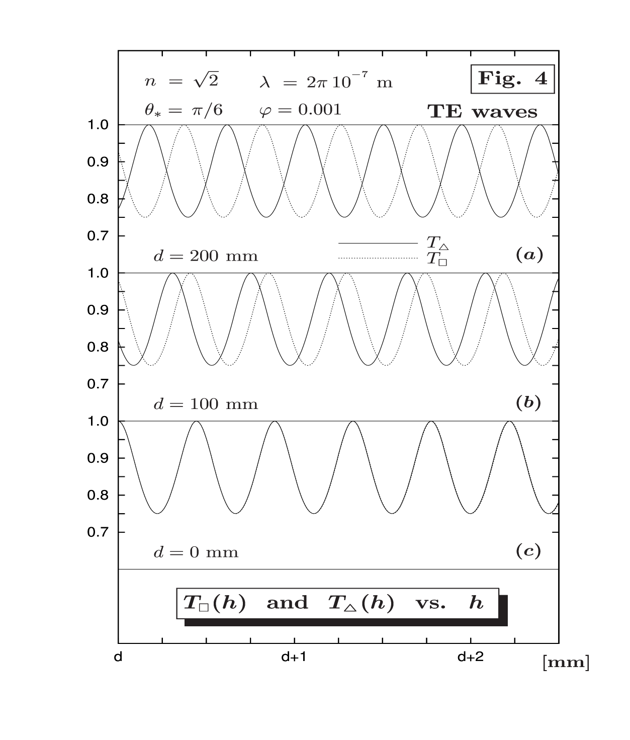
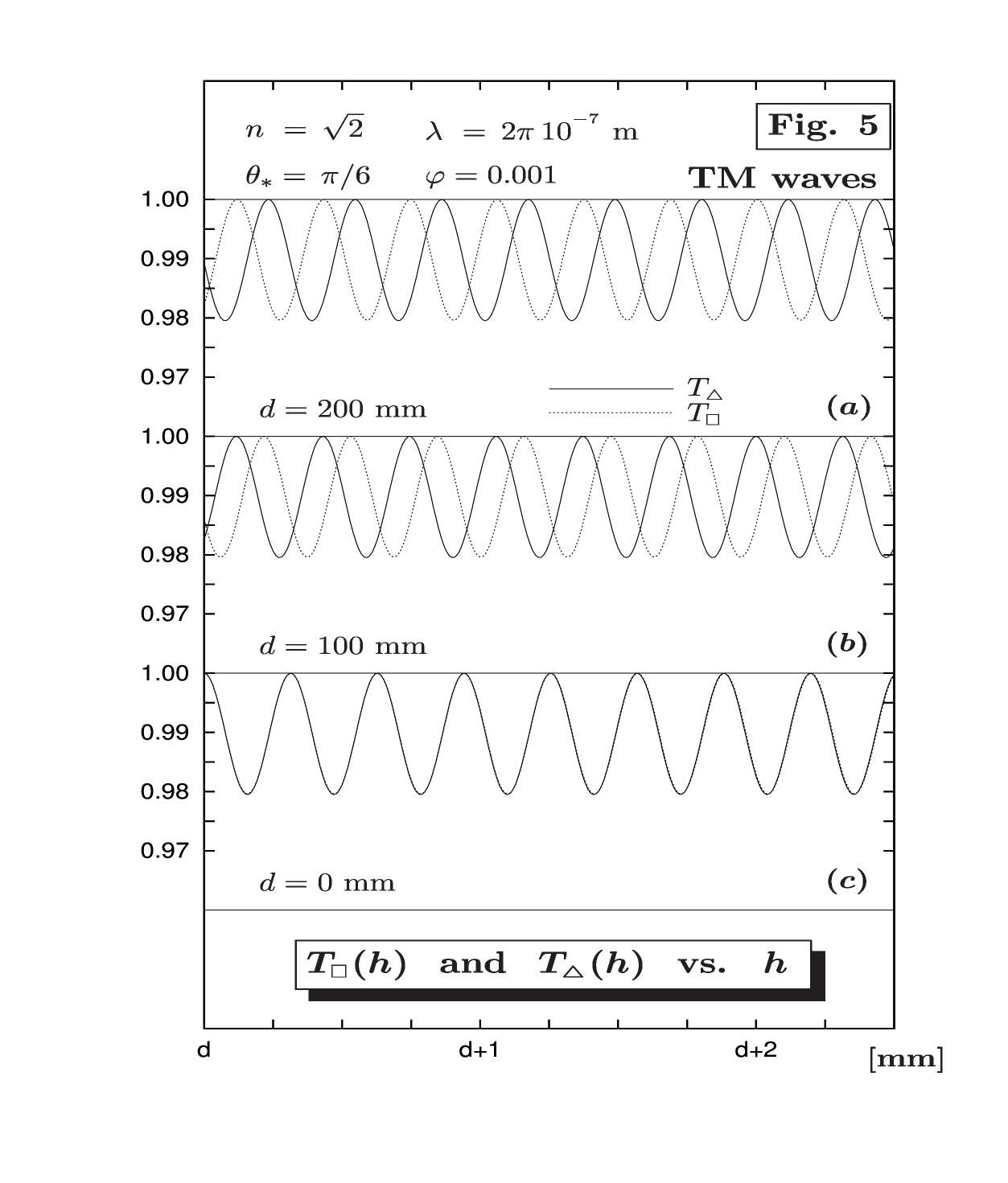
In Fig. 4 (TE waves) and Fig. 5 (TM waves), we plot the transmission probabilities, (23) and (24), for (, ) in the case of diffusion, . Deviations are evident for incidence points of light of order of 10 cm.
For incidence angles very close to the critical angle
we find
| (26) |
where
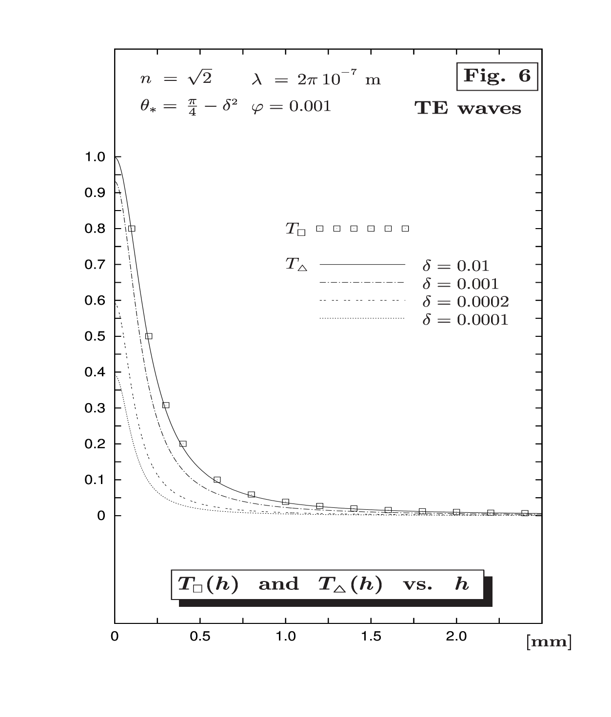
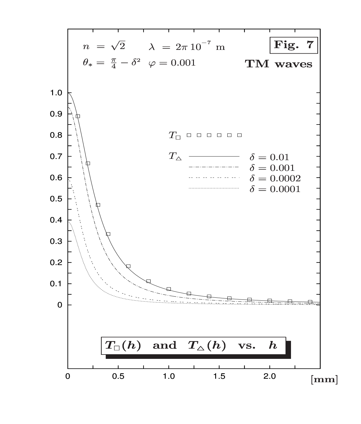
In Fig. 6 (TE waves) and Fig. 7 (TM waves), we compare the new results with formula (2). Deviations are evident for . Nevertheless, the localization, , of the incoming beam gives a constraint on this parameter,
For a beam waist of the order of mm and a wavelength m, we find
and no difference can be seen between the two formulas. This suggests that differences between the standard and the new formulas can be only seen for light diffusion and not for tunneling of light. Experiments can be prepared by an appropriate choice of . Observe that by increasing the angle , we anticipate the shift between the resonances (for example ) but we drastically increase the number of resonances ( in a few mm). The choice of the best essentially depends on the laser wavelength.
ACKNOWLEDGEMENTS
The authors thank the CNPq, grant PQ/2010-2013 (S.D.L), and FAPESP, grant 2011/08409-0 (S.A.C) for financial support. The author also thanks the referee for his suggestions and for drawing attention to reference [24] on the multiple scattering approach.
REFERENCES
- [1] M. Born and E. Wolf, Principles of optics, Cambridge UP, Cambridge (1999).
- [2] K. K. Sharma, Optics, Elsevier AP, San Diego (2006).
- [3] B. E. A. Saleh and M. C. Teich, Fundamentals of photonics, Wiley, New York (2007).
- [4] J. C. Bose, On the influence of the thickness of air-space on total reflection of electric radiation, Proc. R. Soc. London 62 300-310 (1897).
- [5] E. E. Hall, The penetration of totally reflected light into the rarer medium, Phys. Rev. 15, 73-106 (1902).
- [6] I. Newton, Optics, Dover, New York (1952).
- [7] F. L. Baida, D. V. Labeke, and J. M. Vigoureux, Numerical study of the displacement of a three dimensional Gaussian beam transmitted at total internal reflection. Near-field applications, J. Opt. Soc. Am. A 17, 858-866 (2000).
- [8] A. Haibel, G. Nimtz, and A. A. Stahlhofen, Frustated total reflection: the double-prism revised, Phys. Rev. E 63, 047601-3 (2001).
- [9] J. Broe and O. Keller, Quantum-well enhancement of the Goos Haenchen shift for p-polarized beams in a two prisms configuration, J. Opt. Soc. Am. A 19, 1212-1222 (2002).
- [10] D. A. Papathanassoglou and B, Vohnsen, Direct visualization of evanescent optical waves, Am. J. Phys. 71, 670-677 (2003).
- [11] C. F. Li and Q. Wang, Prediction of simultaneously large and opposite generalized Goos-Haenchen shifts for TE and TM light beams in an asymmetric double-prism configuration, Phys. Rev. E 69, 055601-4 (2004).
- [12] Y. You, X. Wang, S. Wang, Y. Pan, and J. Zhou, A new method to demonstrate frustrated total internal reflection in the visible band, Am. J. Phys. 76, 224-228 (2008).
- [13] Z. Vörös and R. Johnsen, A simple demonstration of frustrated total internal reflection, Am. J. Phys. 76, 746-749 (2008).
- [14] S. De Leo and P. Rotelli, Localized beams and dielectric barriers, J. Opt. A 10, 115001-5 (2008).
- [15] S. De Leo and P. Rotelli, Laser interaction with a dielectric block, Eur. Phys. J. D 61, 481-488 (2011).
- [16] I. N. Court and F. K. Willisen, Frustrated total internal reflection and application of its principle to laser cavity design, Appl. Optics 3, 719-726 (1964).
- [17] S. Zhu, A. W. Yu, D. Hawley and R. Roy, Frustrated total internal reflection: a demonstration and review, Am. J. Phys. 54, 601-607 (1986).
- [18] J. C. Castros, Optical barrier penetration: a simple experimental arrangement, Am. J. Phys. 43, 107-108 (1974).
- [19] C. C. Tannoudji, B. Diu and F. Lalöe, Quantum Mechanics, Wiley, Paris (1977).
- [20] D. J. Griffiths, Introduction to quantum mechanics, Prentice Hall, New York (1995).
- [21] A. Bernardini, S. De Leo, and P. Rotelli, Above barrier potential diffusion, Mod. Phys. Lett. A 19, 2717-2725 (2004).
- [22] S. De Leo and P. Rotelli, Tunnelling through two barriers, Phys. Lett. A 342, 294-298 (2005).
- [23] S. De Leo and P. Rotelli, Above barrier Dirac multiple scattering and resonances, Eur. Phys. J. C 46, 551-558 (2006).
- [24] A. Anderson, Multiple scattering approach to onedimensional potential problems, Am. J. Phys. 57, 230-235 (1989).
- [25] Von K. Försterling, Über die Messung der optichen Konstanten sehr dünner Metallshishten, Ann. Phys. 422, 745-751 (1937).