States of motion in an AC liquid film motor: experiments and theory
Abstract
The liquid film motor (LFM) is a simple device which serves as a laboratory to conduct experimental research in basic theoretical studies of electrohydrodynamics (EHD). In addition the LFM can play an important role in technological applications such as micro mixers and washers. In this paper we initially performed experiments to examine the theory regarding rotation and vibration of an AC LFM. While many theoretical predictions are in agreement with our experimental data, but in the threshold of vibration there is an obvious disagreement; we showed that no threshold exists and oscillation is observed in any field value. Experimental evidence showed the existence of an elastic deformation in water before reaching the yield stress and lead us to the use of the elastic Bingham fluid model. We revised the theories using this model and investigated the behaviour of a vibrating LFM which has more applications in mixing. We applied a numerical solution to derive different phases of vibration and distinguish between elastic and plastic vibrations, the latter which could be used for mixing.
- PACS numbers
-
47.65.-d, 68.15.+e, 83.60.La
I Introduction
Quasi two-dimensional suspended liquid films serve as a laboratory to study hydrodynamical characteristics of two dimensional fluid flows, which has received intensive attention Chomaz and Cathalau (1990); Couder et al. (1989); Rivera and Wu (2000); Sur and Kyu Pak (2001); Langevin et al. (2011); Sonin (1998); Sheludko (1967). Applying an electric field to liquid or liquid crystalline films can produce electro-hydrodynamical(EHD) flows in the films, a topic which has attracted much interest due to its wide range of applications specially in micro and nano scale Espin et al. (2013); Shirsavar et al. (2012); Zhao and Yang (2012); Sun and Morgan (2011); Lee et al. (2011); Dittrich and Manz (2006); Stone et al. (2004); Morris et al. (1990). The applications involve microfluidic devices such as dispensers, mixers, motors, separators, pumps and other functional units that are needed for a lab on a chip systems Stone et al. (2004); Dittrich and Manz (2006) or drug delivery, environmental and food monitoring, biomedical diagnoses and chemical analyses, etc Zhao and Yang (2012). Our goal in this paper is to study the physics of such EHD phenomenon in the case of the liquid film motor (LFM).
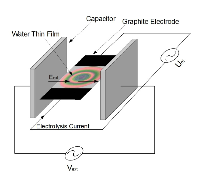
We previously introduced an experimental device which can induce pure rotations in water suspended films Amjadi et al. (2009); Shirsavar et al. (2011, 2011, 2012). The device is consisted of a two-dimensional electrolysis frame connected to a pair of electrodes which conduct electric current through the liquid film. The frame is located inside a large parallel plate capacitor which produces external electric field in the plane of the film (figure 1). By changing the magnitudes of the electric current and the applied external electric field, the threshold conditions for the onset of rotation has been obtained. The direction and the speed of rotation can be controlled through manipulation of the direction and the strength of the current and/or external electric field. Our experiments showed that the rotation direction of the induced vortices is strictly related to the directions of the applied fields and it obeys the right-hand rule (). We have observed that the rotation exists for polar liquids like Aniline, Anisole and Chlorobenzene. The experiments show that the threshold of the fields for the on-set of rotation is in the same order of magnitude for many polar liquids Shirsavar et al. (2011), irrelevant to their conductivity, viscosity and density values. We have also studied the effect of phase and frequency on the rotation of the film Shirsavar et al. (2011). On AC LFM, when external electric field , and electrolysis current , are in phase having the same frequencies, the direction of the fields reverse alternatively and simultaneously so that the direction of rotation remains unchanged (direction of remains unchanged). If the fields would have different frequencies, the application of external and internal fields to the film cannot produce rotating vortices but it causes vibrational movements. If the applied alternating fields have exactly the same frequencies the liquid film rotates. In this case, the threshold and velocity of the rotation depend on the time phase difference between the fields and their magnitudes.
The remote and reversible control over the fluid can be used in mixing of confined liquids in miniaturized devices. Our efficient control over the fluid can be used in active mixers which use external forces for mixing the samples in special microchannel devices Lee et al. (2011). The mixing can be achieved via the application of noncontact electrodes to microfluidic films. The speed and direction of the mixing can be controlled via the strength and direction of the electric fields (Amjadi et al., 2009) and it can be used to regulate the mixing speed.
The explanation of the rotation mechanism is important in understanding the physics behind the phenomenon. Many attempts have been made to explain the phenomenon in terms of electrohydrodynamics. In 2009, Shiryaeva et al. (2009) suggested a detailed mathematical model on the phenomenon. Their physical perspective was based on the fact that the external filed induces electrically charged areas at the boundaries of the film, and the electric current exerts force and causes rotation. Their theory is based on the edge effects, and the rotation predicted therein is maximum at the edges which is not consistent with experiments. In 2011 Liu et al. (2011) suggested another perspective on this phenomenon. They suggest that the rotation is caused by the continuous competition between the destruction of the polarization equilibrium by the electric current and it’s reestablishment by the external electric field. Their explanation is supported by the picture water in quantum field theory, the existance of coherent domains in which all water molecules oscillate in phase between two configurations. They also explained the fact that a minimum field is needed for the rotation by assuming water film to be a Bingham plastic in presence of an electric field.
The quantum field theory has also been used in explaining other electrohydrodynamical phenomena such as the floating water bridge Del Giudice et al. (2010), which is the suspension of a water thread between two beakers in a high voltage regime Fuchs et al. (2007). But in the case of the floating water bridge, much more attention has been given to theoretical explanations based on classical electrohydrodynamics, neglecting the need of a quantum field theory explanation for that phenomenon Widom et al. (2009); Saija et al. (2010); Marín and Lohse (2010); Aerov (2011); Morawetz (2012), and are shown to be in agreement with experiments Namin et al. (2013).
In a more recent attempt, Liu et al. (2012), presented a model for dynamical characteristics of the AC water film motor. They derived a series of the specific features of this motor, e.g. the threshold conditions for the on-set of vibration and rotation of the film and the influence of the frequencies of the AC fields and their phase differences on EHD motions. Their results for the threshold conditions of the AC fields for the onset of rotation are in agreement with our previous experiments Amjadi et al. (2009).Their model predicts some features which have to be experimentally verified, such as three states of motion in case the fields are in a same frequency but a different phase: rest, vibration and rotation. In case the fields have different frequencies, the theory predicts two states: rest and vibration with specified frequencies.
In this paper, we first construct precise quantitative experiments to test the theoretical predictions in section II. We make use of an image processing technique for the velocimetry, and detect the vibration using Fourier transformation. The experimental results in sec. II mismatch with the theoretical results, therefore we find the mismatch source and develop a revised theory in section III and derive the results by using a numerical solution, leading to a conclusion in section IV
II Experiments
We construct quantitative experiments to examine the theoretical predictions in an AC LFM. The theory Liu et al. (2012) explaines the dynamical behaviour of the film when AC voltages are applied, and in the cases where the applied electric fields have different frequencies or time phases, it predicts the existence of various states of motion in different voltage products.
The general setup of the device consists of a 2D frame with two electrodes on the sides that conduct electric current through the liquid film. The electrodes are subjected to an AC voltage. The liquid film is formed between these electrodes in a circular shape with the diameter of 8.1 mm. In order to apply an AC external electric field to the film, the frame is located between two large parallel metal plates acting like a capacitor (Fig. 1). In all of our experiments the direction of the electric current is perpendicular to the direction of the external electric field to maximize the strength of vibration.
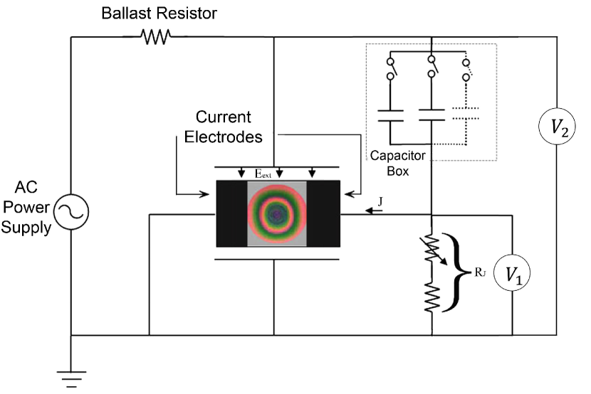
In the first part of our experiments, the electrodes conducting current and the plates producing external electric field are subjected to the same power supply, in order to have fields with equal frequencies of 41 Hz. The phase differences between the fields are generated by a simple Series-Resistance-Capacitance Circuit, as follows: The voltage across the resistance is connected to the electrodes which produce the electric current, while the AC power supply is directly connected to the capacitor to produce (figure 2). By changing the capacitance value of the capacitor, we can produce different phase angles between the electric current and the external electric field. We have tested phase angles of 60, 75 and 85 degrees.
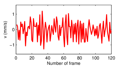
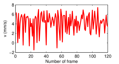
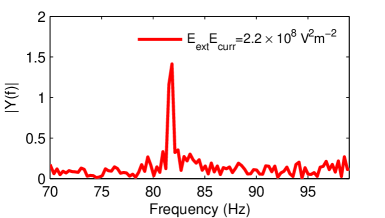
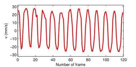
The vibration is quite hard to detect in experiments. The vibration displacements and velocities are not high enough to be detected with naked eye, especially near the expected thresholds of vibration. For this reason a velocimetry program was developed. A method similar to the Particle Imaging Velocimetry (PIV) was applied, with the difference that no tracer particle was used. The color patterns traced on the film were fed into the pattern matching algorithm, and the difference between the patterns of two subsequent frames was used to find the velocity vector field between each two frames. We used a modified version of the open source MatPIV 1.6.1 Sveen (2011) which calculates the velocity vector field by a window-shifting technique for the pattern matching. The tangential velocities were calculated at each point and averaged to find , as plotted against time in figure 3. The vibration was detected by applying a fast Fourier transform to in a period of 10 seconds.
Our experiments verified the existence of a rotatory state of motion in electric fields higher than a specific threshold. We observed that in this case, the rotation is along with a slight vibration as shown in figure 3. In the case of a smaller electric field products than the threshold of rotation, the motion becomes pure vibration as predicted in the theory Liu et al. (2012) and shown in figure 3. The theory predicts that in smaller electric fields, the motion changes to absolute rest, but our experiments did not enable us to examine this fact because the displacements and velocities become smaller than our measuring accuracy.
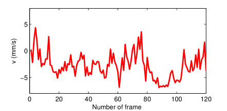
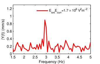
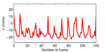
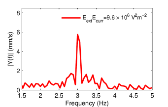
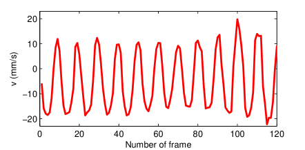
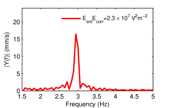
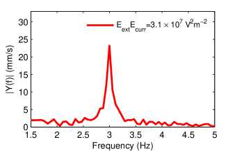
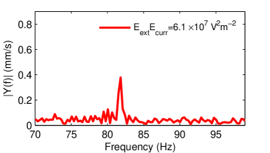
In the second set of experiments, different frequencies were applied to the electrodes and the capacitor. We used the frequency of 53Hz to the electrode and the frequency of 50Hz to the capacitor, thus expecting a vibration of 103Hz and a vibration of 3Hz according to the theory and in the FFT of this frequency was clearly detected. The theory predicts that for voltages smaller than a specific threshold the Bingham plastic causes a state of rest, where no rotation or vibration occurs. Our experiment results showed that this prediction of the theory is not correct, i.e. the state of rest does not exist and vibration was clearly detected in the specified frequency in electric fields far below the thresholds predicted theoretically, as shown in figure 4. Thus the first stage of motion in the AC liquid film motor predicted theoretically Liu et al. (2012) does not exist.
Our other experiments in the DC motor show that when the product of applied voltages is less than the threshold of rotation, a slight angular displacement is observed when the voltages are applied, and a reverse angular displacement is observed when the voltages are turned off. This experimental evidence shows that an elastic deformation takes place when the stresses applied are less than the yield stress i.e. in the case that the Bingham plastic does not show a plastic behaviour, it is not rigid, but deforms elastically when a stress is applied. Based on this explanation, we revisit the theoretical predictions for the AC liquid film motor and study the vibration behaviour in section III.
III Theory revision
Considering the liquid film to be a Bingham plastic in presence of the external electric field (as Liu et al. (2011, 2012)) explains well the steady phenomenon of rotation in a LFM and the thresholds of rotation. This assumption is explained using the quantum field theory; the plasticity of the film is suggested to be caused by long-ordered chains composed of coherent domains with an electric dipole moment resulting from the alignment of the electric dipole moments of their coherently oscillating molecules Liu et al. (2011). In the case when the shear stress is more than a minimum shearing stress () the fluid shows no displacement.
However this assumption does not correctly model the unsteady case of an AC LFM as shown experimentally in section II. In this case, the fluid motion can not be classified in two cases of ’no shear rate’ and ’viscous shear’. Considering the film to be an elastic Bingham fluid is a more accurate assumption for the unsteady case and describes well the experimental data on rotation and vibration of LFM. In this case when the layers of the fluid do not exhibit a plastic flowing deformation, an elastic solid behaviour is expected, i.e. an elastic reversible deformation occurs when a shear stress is applied. It has been shown by Yoshimura and Prud’homme (1987) that elastic Bingham fluids exhibit a vibration when subjected to a variable stress.
To formulate this effect quantitatively, we define an elastic shear strain as a function of time and radius, . A shear stress is applied between each layer which follows the linear relation in which is the shear modulus of water in the elastic range. has a limited range of and if the deformation exceeds this range, the residual deformation is a plastic deformation. is the strain where the maximum elastics stress () is applied, thus .
To define the motion of the film from this point of view, the parameters would be the tangential velocity and the elastic shear strain . The torque exerted to a disc liquid film with a radius of and thickness of is consisted of three moments:
| (1) |
where is the moment caused by the dipole moments and the steady electric field of the electric current, is caused by the viscosity force and is because of the elastic deformation. According to Liu et al. (2011), follows this relation for our system:
| (2) |
where is the torque per unit volume and is equal to in which is vacuum permittivity, is the relative permittivity of the liquid, is the external field applied by the capacitor, is the field causing the electrical current normal to the external field and is the thickness of the film.
The viscous and elastic moments can be calculated using the shear stresses of each effect:
| (3) |
| (4) |
The moment exerted to a ring element of the film with radius to can be calculated by the derivation of the total torque , which results in:
| (5) |
where is the volume of the ring element. This moment will cause an angular acceleration, which can be written in terms of the derivation of u, thus leads to:
| (6) |
where is the density of the fluid.
For the shear strain there must be an equation to be coupled with equation 6 and form the differential equation of motion. The shear strain rate (S) can be calculated as the difference between the rotation of a specific point and the overall rotation of the segment:
| (7) |
but this shear strain is not totally the elastic strain: as it is explained before, the elastic strain must be in the limited range. So the residual strain will be a plastic strain. Thus the derivation of the elastic strain can be formulated as follows:
| (8) |
Equations 8 and 6 form the equations of motion for this system. The boundary conditions for this system is that flow velocity is zero because of the no-slip condition, and there are no shear velocity and shear deformation at the center because of symmetry:
| (9) |
also the initial conditions are:
| (10) |
To solve the equations and obtain results, we applied a numerical method solving the ordinary differential equation system using an explicit Runge-Kutta (4,5) formula, the Dormand-Prince pair Dormand and Prince (1980).
The results are highly dependant on the amount of maximum shear strain assumed. In experiments the elastic displacement of the film in connecting and disconnecting the electric fields was clearly visible, so we have estimated the maximum shear angle to be in the order of one degrees.
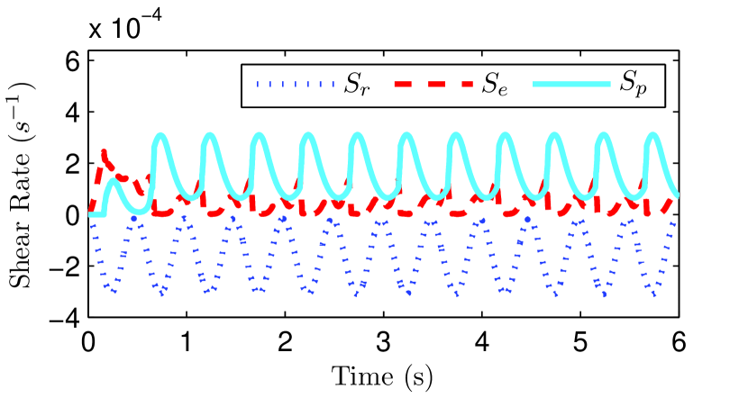
For the case where the applied voltages are of a similar frequency and have a phase difference, our simulation shows the existence of two different possible stages of motion: vibration with no net rotation and rotation plus vibration. Note that as explained above, the state of rest does not exist. In addition to this, the state of vibration can be divided into two different cases: one where the vibration exhibits a plastic motion, or where it is caused only by elastic deformation. The difference is not distinguishable in experiments, but it has high impact in mixing application, i.e. a vibration with elastic deformations is not a cause of detachment of the fluid particles and is not suitable for mixing. To evaluate this effect quantitatively, we define the elastic shear rate () and plastic shear rate () in the liquid film as follows respectively:
| (11) | |||
| (12) |
and also define a rotatory shear rate that is:
| (13) |
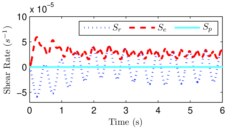
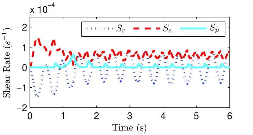
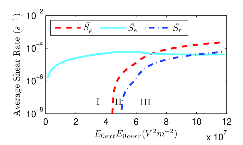
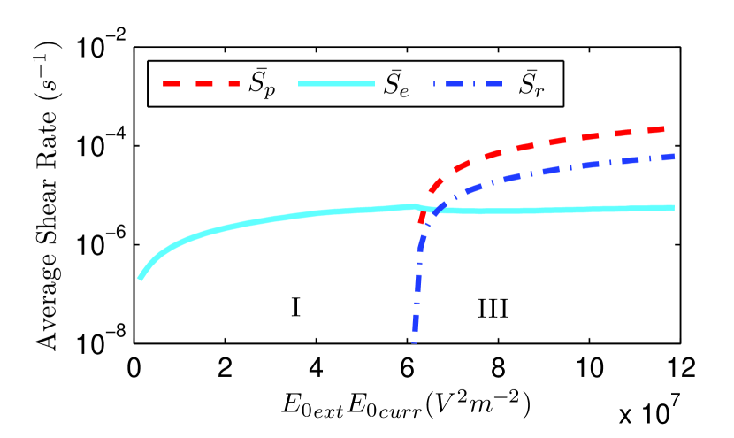
The averages of the shear rates in a full period in a time when the motion has reached a steady rotation and vibration is defined as , and respectively. Monitoring these values in specific fields, phase differences and frequencies leads to an estimation on the amount of elastic vibration, plastic vibration and rotation in a state of motion. Figure 5 shows this behaviour in three cases. In the case that the frequencies are the same but with a phase difference, there might be three states of motion: elastic vibration, plastic vibration and rotation. Note that the state of rest predicted by Liu et al. (2012) has been replaced by the state of elastic vibration. The threshold between elastic and plastic vibrations depend on the frequency of the fields, i. e. in a high frequency, there will not be enough time to deform and reach the maximum strain to lead to a plastic deformation even though the stress is large enough to cause a plastic deformation. This fact has been visualized in figure 6, comparing , and for two cases of and . It is also seen that in high frequencies, the state of plastic vibration gets rare and the motion shifts from elastic vibration to rotation right away by increasing the fields. The plastic vibration is of special importance for it can be used for micro mixing Liu et al. (2013), and our results show that it is rare in high frequencies.
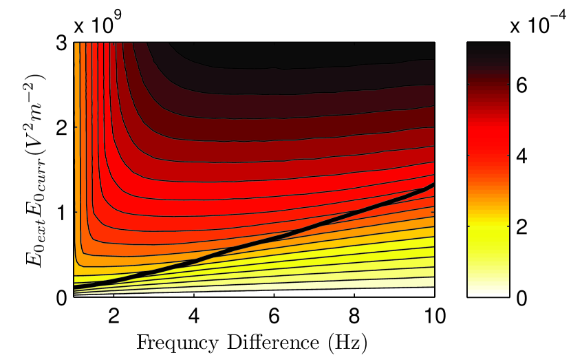
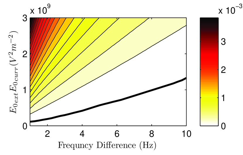
Our theory also leads to changes of results in the case when the frequencies of the two applied fields are different. The state of rest will disappear, and the vibration will be consisted of two phases of elastic and plastic vibration. A threshold will appear that with electric fields smaller than that, no plastic vibration will be present. As shown in figure 7, this threshold increases in higher frequencies, i.e. with the increase of frequency, a higher electric field is needed to cause a plastic deformation because deformations and velocity changes occur in a smaller time. Figure 7 shows how the amount of elastic and plastic vibrations change in different frequencies and electric fields.
IV Conclusion
We performed experiments to examine the predictions of theories regarding the AC liquid film motor. We constructed the setup for the AC fields with different frequencies and used a velocimetry image processing to obtain the vibration velocity. Many predictions of the theories of Liu et al. Liu et al. (2011, 2012) are the same as our experimental results, in the case of same frequencies with phase difference between the electric fields and in the case of frequency differences the rotation and vibration were observed and the vibration frequency matches the predictions therein. It was observed that in the case of phase differences, vibration and rotation exist simultaneously and by increasing the electric fields, the ratio between vibration and rotation velocities change. In high electric fields, the rotation will be dominant while in lower fields the vibration dominates.
Our experimental results also showed that in the case of different frequencies the state of rest which was predicted in the theory did not occur and vibrations exist in any electric field strengths. We found that for explaining this inconsistency it is adequate to apply an elastic Bingham fluid model instead of the previous Bingham plastic model in the theory. We revised the theory considering this model and used a numerical solution. The results are in good agreement with our experimental findings.
We define a maximum elastic shearing strain for water in electric fields and distinguish between the elastic and plastic vibrations. The plastic vibration can be used for application in mixing, while the elastic vibration is not. Our theoretical results show that in high frequencies for the case of a phase difference, by increasing the fields the state of elastic vibration changes to rotation and the state of plastic vibration diminishes.
As a final conclusion in the application of mixing, lower frequencies and higher electric field strengths are required, otherwise an elastic vibration may occur with no benefit on mixing. The threshold of the frequency and electric fields depend on the dimensions and the electric properties of the liquid.
Acknowledgements.
We greatly thank Dr. R. Shirsavar and Prof. S. W. Morris for their helpful comments at the initial stages of the work and also Dr. Z-Q. Liu for the discussions about this effect and his helpful remarks. This work is funded by Applied Physics Research Center of Sharif University of technology and all the experiments were performed at the Medical Physics Laboratory of the Physics Department.References
- Chomaz and Cathalau (1990) J. Chomaz and B. Cathalau, Physical Review A 41, 2243 (1990).
- Couder et al. (1989) Y. Couder, J. Chomaz, and M. Rabaud, Physica D: Nonlinear Phenomena 37, 384 (1989).
- Rivera and Wu (2000) M. Rivera and X.-L. Wu, Physical Review Letters 85, 976 (2000).
- Sur and Kyu Pak (2001) J. Sur and H. Kyu Pak, Phys. Rev. Lett. 86, 4326 (2001), URL http://link.aps.org/doi/10.1103/PhysRevLett.86.4326.
- Langevin et al. (2011) D. Langevin, C. Marquez-Beltran, and J. Delacotte, Advances in colloid and interface science 168, 124 (2011).
- Sonin (1998) A. Sonin, Freely suspended liquid crystalline films (Wiley, 1998).
- Sheludko (1967) A. Sheludko, Advances in Colloid and Interface Science 1, 391 (1967).
- Espin et al. (2013) L. Espin, A. Corbett, and S. Kumar, Journal of Non-Newtonian Fluid Mechanics (2013).
- Shirsavar et al. (2012) R. Shirsavar, A. Amjadi, M. Ejtehadi, M. Mozaffari, and M. Feiz, Microfluidics and nanofluidics 13, 83 (2012).
- Zhao and Yang (2012) C. Zhao and C. Yang, Microfluidics and nanofluidics 13, 179 (2012).
- Sun and Morgan (2011) T. Sun and H. Morgan, in Electrokinetics and Electrohydrodynamics in Microsystems (Springer, 2011), pp. 1–28.
- Lee et al. (2011) C.-Y. Lee, C.-L. Chang, Y.-N. Wang, and L.-M. Fu, International journal of molecular sciences 12, 3263 (2011).
- Dittrich and Manz (2006) P. S. Dittrich and A. Manz, Nature Reviews Drug Discovery 5, 210 (2006).
- Stone et al. (2004) H. A. Stone, A. D. Stroock, and A. Ajdari, Annu. Rev. Fluid Mech. 36, 381 (2004).
- Morris et al. (1990) S. W. Morris, J. R. de Bruyn, and A. May, Physical review letters 65, 2378 (1990).
- Amjadi et al. (2009) A. Amjadi, R. Shirsavar, N. H. Radja, and M. Ejtehadi, Microfluidics and nanofluidics 6, 711 (2009).
- Shirsavar et al. (2011) R. Shirsavar, A. Amjadi, A. Tonddast-Navaei, and M. Ejtehadi, Experiments in Fluids 50, 419 (2011).
- Shiryaeva et al. (2009) E. Shiryaeva, V. Vladimirov, and M. Y. Zhukov, Physical Review E 80, 041603 (2009).
- Liu et al. (2011) Z.-Q. Liu, Y.-J. Li, G.-C. Zhang, and S.-R. Jiang, Physical Review E 83, 026303 (2011).
- Del Giudice et al. (2010) E. Del Giudice, E. C. Fuchs, and G. Vitiello, Water 2 (2010).
- Fuchs et al. (2007) E. C. Fuchs, J. Woisetschläger, K. Gatterer, E. Maier, R. Pecnik, G. Holler, and H. Eisenkölbl, Journal of Physics D: Applied Physics 40, 6112 (2007).
- Widom et al. (2009) A. Widom, J. Swain, J. Silverberg, S. Sivasubramanian, and Y. Srivastava, Physical Review E 80, 016301 (2009).
- Saija et al. (2010) F. Saija, F. Aliotta, M. Fontanella, M. Pochylski, G. Salvato, C. Vasi, and R. Ponterio, The Journal of chemical physics 133, 081104 (2010).
- Marín and Lohse (2010) Á. G. Marín and D. Lohse, Physics of Fluids 22, 122104 (2010).
- Aerov (2011) A. A. Aerov, Physical Review E 84, 036314 (2011).
- Morawetz (2012) K. Morawetz, Physical Review E 86, 026302 (2012).
- Namin et al. (2013) R. M. Namin, S. A. Lindi, A. Amjadi, N. Jafari, and P. Irajizad, arXiv preprint arXiv:1210.2913 (2013).
- Liu et al. (2012) Z.-Q. Liu, G.-C. Zhang, Y.-J. Li, and S.-R. Jiang, Physical Review E 85, 036314 (2012).
- Sveen (2011) J. K. Sveen, Preprint series. Mechanics and Applied Mathematics (2011).
- Yoshimura and Prud’homme (1987) A. Yoshimura and R. Prud’homme, Rheologica acta 26, 428 (1987).
- Dormand and Prince (1980) J. R. Dormand and P. J. Prince, Journal of computational and applied mathematics 6, 19 (1980).
- Liu et al. (2013) Z.-Q. Liu, Y.-J. Li, K.-Y. Gan, S.-R. Jiang, and G.-C. Zhang, Microfluidics and Nanofluidics 14, 319 (2013).