Liquid meniscus friction on a wet plate: Bubbles, lamellae and foams
Abstract
Many microfluidics devices, coating processes or diphasic flows involve the motion of a liquid meniscus on a wet wall. This motion induces a specific viscous force, that exhibits a non-linear dependency in the meniscus velocity. We propose a review of the theoretical and experimental work made on this viscous force, for simple interfacial properties. The interface is indeed assumed either perfectly compressible (mobile interface) or perfectly incompressible (rigid interface). We show that, in the second case, the viscous force exerted by the wall on the meniscus is a combination of two power laws, scaling like and , with the capillary number. We provide a prediction for the stress exerted on a foam sliding on a wet solid and compare it with experimental data, for the incompressible case.
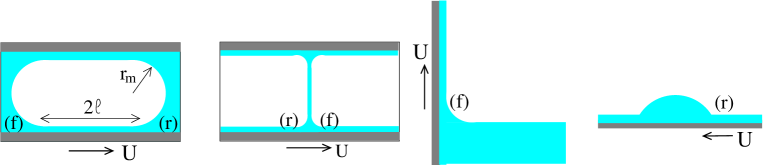
Many industrial or natural situations involve the motion of liquid menisci on a wet solid. For enhanced oil recovery hirasaki85 ; rossen90a ; kornev99 , or soil remediation chowdiah98 , liquid foams are pushed into porous media to displace oil or pollutants; surfactant lamellae are produced in the lung and move in the bronchial tubes grotberg01 ; howell00 ; innovative set-ups are developed to control bubbles motion in micro-channels for lab-on-a-chip applications baroud10 ; pulling a solid out of a liquid bath is a common way used in industry for coating quere99 .
As depicted in Fig. 1, the same local flow is observed close to the wall in all these examples. While the meniscus moves on the wall, it deposits a thin wetting film. Its thickness, of the order of few tens of microns, depends on the meniscus velocity through the capillary number that compares the viscous stress and the capillary pressure, through the values of the solution viscosity , the surface tension and the meniscus velocity . This property, that makes possible a finely tunable coating, has been widely investigated quere99 . In contrast, the force required to pull a meniscus at a given velocity on a wall is much less understood, and plays a crucial role for the motion of confined bubbles or confined foams. This force is governed by the velocity gradients in the liquid phase. As the liquid phase is confined into the small gaps between the bubbles and the wall, these gradients, and consequently the viscous force, are strongly enhanced and depend on the dynamical shapes of the meniscus and of the wetting film. As a direct consequence, pushing a foam in a tube requires a pressure drop that is much higher than the one needed to push the surfactant solution in the same tube at the same mean velocity hohler05 ; livre_mousse .
The theoretical prediction of the shape of the deposited film has been proposed by Landau and Levich landau42 and by Derjaguin derjaguin43 (LLD) in the limit of small capillary numbers. Bretherton bretherton61 and Park and Homsy park84 adapted this calculation to the case of a confined bubble and predicted the pressure drop associated with the bubble motion. Experimental results mainly report on the film thickness deposited by long bubbles in cylindrical tubes fairbrother35 ; taylor61 ; bretherton61 ; chen86 ; schwartz86 ; aussillous00 ; emile12 or on solids pulled out of a bath (quere99 and references therein, chan12 ), for a typical range of capillary number . The viscous force acting on the meniscus, or the pressure drop, have been measured for different systems including bubbles separated by liquid slugs cubaud04 ; fuerstman07 or lamella hirasaki85 ; cantat04 ; terriac06 ; dollet10 ; bazilevsky12 moving in tubes, and foams in 2D raufaste09 or 3D geometries denkov05 ; marze08 . Numerical simulations have extended the predictions for the meniscus induced pressure drop to higher capillary numbers or to more complex geometries reinelt85 ; reinelt87 ; ratulowski89 ; martinez90 ; giavedoni97 ; heil01 ; hazel02 ; saugey06 ; fujioka08 .
Lamella and foams are stabilized by surfactants that induce a specific stress at the interface. If the area of an interface element increases fast enough, the surfactant concentration decreases and the surface tension increases, thus acting against the extension. The dilatational modulus of the interface, defined as , is a measure of this phenomenon. Moreover the intrinsic viscosity of the surfactant monolayer induces an additional interfacial stress, that also acts against the extension. In the limit of high dilatational modulus or high interfacial viscosity, the interface behaves as an incompressible surface.
In this paper, we discuss the motion of a meniscus on a wet wall, in the ideal cases of incompressible interfaces or interfaces with uniform tangential stress. The results obtained in these limiting cases constitute important references for models with more realistic interfacial properties. Section I presents classical calculations for the dynamical meniscus shape, from which the viscous forces are deduced in Section II, as well as the validity range of the ideal models. An original derivation of the pressure drop for a single bubble is proposed in Section III and compared with Bretherthon’s calculation. Finally, adapting Denkov’s approach denkov05 , these results are used in Section IV to derive predictions for the foam/wall tangential stress as a function of the bubble size and liquid fraction, for stress-free or incompressible interfaces. For incompressible interfaces, we show that the stress is not a power law of the capillary number as usually assumed, but rather a sum of two contributions scaling as and , in good agreement with experimental results.
I Dynamical meniscus shape
I.1 Resolution of the lubrication problem
We consider a liquid meniscus moving at constant velocity in the direction on a solid plate, in steady state. We assume an invariance in the direction (see the convention of orientation on Fig. 2) and we neglect inertial and gravitational effects. In the meniscus frame, a positive plate velocity corresponds to a plate pulled out of a bath as in the Landau Levich problem, to the front end of the bubble as in the Bretherton problem or to the rear side of lamella (see Fig. 1). Keeping the Bretherton notation, this case is called the front meniscus, denoted by in the following. Conversely, corresponds to a plate plunging into a bath, to the rear end of the Bretherton’s bubble, to a drop spreading on a wet plate or to the front side of a lamella, and is called the rear meniscus, denoted by .
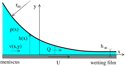
This problem is governed by the Stokes equation, in the lubrication regime. We denote the pressure in the liquid phase , the velocity in the direction and the film thickness . The fluid viscosity is and the surface tension . The equation of motion can then be written as:
| (1) |
Using this leads to
| (2) |
The continuity of tangential stress provides the boundary condition at the interface.
| (3) |
The exact expression for depends on the physico-chemical properties of the solution. This interfacial stress is denoted by in eq. 1, which implicitly assumes that, at dominant order in , , the equilibrium surface tension. The explicit notation and will be used to discuss the small difference between both terms. Elsewhere we will keep the generic notation . Without surfactant is exactly verified, and the relation (3) imposes at the interface. This case is the stress free case denoted in the following. In the opposite limit of incompressible interface, the boundary condition is div, with div2D the divergence in the plane tangent to the interface and the interfacial velocity. Consequently, small variations of the interfacial stress occur along the interface, discussed in section II.2.2. In our geometry, because the flow is quasi-parallel and invariant in the direction, div simplifies into . The incompressibility of the interface thus implies that is constant. This uniform velocity is imposed by an external condition, in the static meniscus or in the wetting film and may a priori take any value, depending on the whole experimental situation. In this paper, two particular values are considered. The case will be called the rolling case : in the region of interest, close to the wall and to the meniscus, the interface makes a rotation around the bubble in the bubble frame and has no relative motion with respect to the wall. The case is the sliding case : the interface is locally immobile in the bubble frame and slides on the moving wall.
In order to take into account these three different boundary conditions (, and ) within the same formalism, we use a general velocity expression that depends on the two parameters and , as summarized below:
| (4) |
Finally, we impose the condition that the wetting film is flat far from the meniscus, with a thickness . The flux (per unit length in the z direction) in the flat region is and flux conservation leads to the central relation
| (5) |
with and . By convention, we use the upper sign (here ) for the front meniscus and the lower sign (here ) for the rear meniscus.
For the different boundary conditions we obtain:
-
•
Stress free case (): , ,
-
•
Sliding case (): , ,
-
•
Rolling case (): , ,
We now define the dimensionless quantities , , and rescale equation (5) into
| (6) |
The boundary conditions are , and . The problem is finally closed with the matching condition , with the static meniscus radius of curvature. This condition is equivalent to
| (7) |
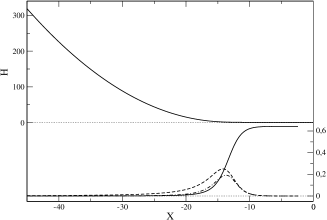
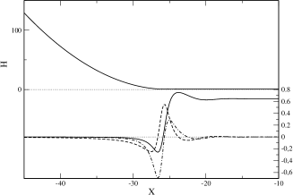
A numerical resolution requires the determination of boundary conditions at finite distances, and these are obtained from the linearized problem. At large , is close to 1 and the problem can be linearized using a small parameter . The governing equation (6) becomes , which has solutions of the form , with . For the front meniscus is the only root with a negative real part and the solution can be used to determine the values , and needed to solve eq. 6 numerically. Changing the arbitrary value of only translates the solution along the direction. The unique solution is shown on Fig. 3 (inset). The numerical value of is , and, from eq. 7, we recover the classical results shen02
| (8) |
In the case of a plate pulled out of a liquid, the result is usually expressed as a function of the capillary length , with the solution density and the gravity. Due to the hydrostatic pressure, the meniscus curvature changes with the height and can be shown to be at the top of the meniscus. The film thickness is thus, in the stress free case, .
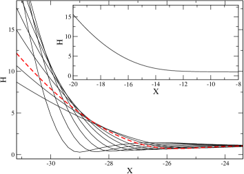
For the rear meniscus, the linearized equation admits two roots with a negative real part . The general solution of the linearized equation is thus
| (9) |
Different values of just translate the solution, but different values of lead to different solutions, with converging to a large range of possible values (positive or negative) when giavedoni99 . The family of rear meniscus profiles are represented on Fig. 3. This states that, for a given meniscus radius of curvature, we can find a steady solution for any film thickness initially present on the wall. In the following discussion, the profile with , as for the front meniscus, will be denoted by the subscript . It plays an important role, as it is the shape obtained when the rear meniscus moves on the wetting film deposited on the wall by a front meniscus of same radius, moving at the same velocity.
I.2 Asymptotic parabolic shapes
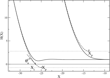
The asymptotic expression for the film thickness for is a parabolic profile , with the position of the minimum of the parabola and duffy97 . Both and need to be determined numerically. The best numerical fit, plotted on Fig. 4, have been obtained with for the front meniscus with in the range . A slightly smaller value, is reported in bretherton61 and is found when the fit is performed for in the range .
For the rear meniscus, we found . Its asymptotic profile thus intersects the wall at the contact point shown in Fig. 4. The apparent contact angle , also shown in Fig. 4, has been computed for any initial wetting film thickness in chebbi03 . It can be deduced from the parabola equation: and from the relation . For the three boundary conditions considered, we get, for the solution:
| (10) |
These relations are very similar to Tanner’s law, which describes the spreading of a droplet on a solid wall in the perfect wetting case tanner79 ; degennes85 ; bico01 ; cormier12 . However, for a spreading droplet, the profile far from the wall is not parabolic, but rather close to a straight wedge. In that case, the apparent contact angle involves a logarithmic term. Indeed, imposing the boundary conditions when and when in eq. (5) leads to tanner79 ; degennes85
| (11) |
The micro-scale cut off is obtained by matching the film profile to a precursor film initially present on the wall and governed by Van der Waals forces : , with the Hamaker constant degennes85 .
I.3 Comparison with some experimental data
I.3.1 Wetting film thickness in the LLD geometry
The wetting film thickness as a function of the plate velocity has been extensively studied for the front meniscus in the LLD geometry, with fibers or plates pulled out of pure liquids or surfactant solutions.
The stress free result is obtained for pure liquids. For surfactant solutions, the whole range of thicknesses between and are observed, depending on the surfactant concentration, the imposed velocity and, for the fiber case, the fiber radius quere99 ; scheid10 .
In LLD geometries, surfactant solutions with high surface modulus lead to a wetting film thickness in good agreement with the rolling case.
While the solid is pulled out of the liquid reservoir, the total interfacial area increases: the new area is produced at the free interface of the liquid reservoir, in agreement with the rolling assumption. This is confirmed by recent velocity field measurements in the reservoir mayer12 .
The sliding case implies that the whole wetting film is sheared. It is thus incompatible with a very long wetting film (see section II.2.3 for a quantitative discussion). It is therefore not observed in the LLD geometry, but can be obtained for bubbles, as discussed below.
I.3.2 Film profile for bubbles with incompressible interfaces
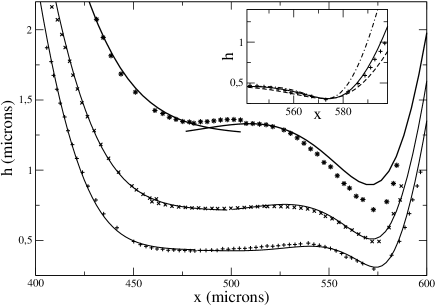
The film profiles shown in Fig. 5 were measured by Denkov et al. using interferometry, for a solution of very high dilatational surface modulus denkov06 . We compare these experimental results with the rear and front solutions of eq. (6). As the meniscus curvature is the same on both sides we use the solution for the rear meniscus. The coordinates and are deduced from the numerical solution using the experimental capillary number , the film thickness (measured in the middle of the film) and a translation parameter that is independently fitted for the rear and front parts of the profile. The three possible values of have been tested. For the two slower cases, the rear and front solutions nicely overlap on the central region and a very good fit is obtained using (sliding case). The profiles obtained for (stress free) and (rolling) are also plotted on Fig. 5(inset) for one meniscus and show a significatively worse agreement with the experimental profile. It thus confirms that the foaming solution used, containing insoluble surfactants, leads to a sliding regime in this geometry, as already assumed in denkov06 .
At larger velocities, the contact area between the bubble and the wall, i.e. the area of the central flat film, decreases and eventually disappears. The two solutions and are both determined by assuming a flat film far from the meniscus and are thus not valid anymore. In that regime, the whole hydrodynamical problem, involving the two meniscus at the same time, should be solved.
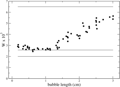
I.3.3 Flux around a bubble for pure water
An indirect measurement of the wetting film thickness has also been obtained by Schwartz, Princen and Kiss schwartz86 for the case of a bubble in pure water. They pushed a single bubble along a tube of radius and measured the solution flux in the bubble frame . They report a fractional speed difference defined by . From eq. 4, we predict and . Finally we get , and , that we compare with the experimental data in Fig. 6. The flux measured for short bubbles is in nice agreement with the stress free prediction, as expected for pure water. However, for long bubbles (more than 1.5 cm for a 1mm inner diameter tube) the flux increases progressively, which is in contradiction with a transition toward a sliding case, for which a smaller flux is expected. In that case, the experimental observation is instead compatible with a transition toward a rolling case, as observed in LLD geometry park92 .
It is not clear why the regime is modified with the bubble length in this case and, more generally, what determines the sliding or rolling regime in the limit of incompressible interfaces. Note that for a bubble in a cylindrical tube, the flow is necessary axisymmetric. The rolling case is thus not compatible with the incompressibility of the interface at the global scale, as some interface needs to be created at the front and suppressed at the rear of the bubble.
II Viscous forces in a meniscus
II.1 Theoretical predictions
The viscous force exerted by the solid wall on the liquid (per unit length of meniscus in the direction) can be deduced from the velocity expression eq. 4.
| (12) |
The first term converges at and and corresponds to a viscous stress localized in a small domain close to the apparent contact point between the meniscus and the wetting film, as shown in dimensionless form on Fig. 7. This domain is usually called the dynamical meniscus, and its extension scales with , i.e. as , with a prefactor discussed in section II.2.3.
The second term diverges at and only appears for the sliding case () for which the whole wetting film is sheared. It thus imposes a cut-off length corresponding to the actual length of the wetting film. Expressed in term of the universal function the force (per unit length) is given by:
| (13) |
with , and . As depends on , the last term introduces some additional dependence into the viscous force.
a
 b
b
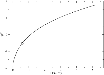
In the front meniscus, everywhere, implying that the viscous force exerted by the wall is positive, as expected for . The numerical integration leads to . In comparison, the rear meniscus is oscillating around and, as underlined in bretherton61 , the sign of the force depends on the value of . We discuss this point in section III.1.1. The value of is plotted as a function of in Fig. 8. For the profile, we find and thus, as for the front meniscus, a viscous force exerted by the wall in the direction of its own motion. The vanishing force corresponds to , which implies .
The wetting film contribution tends to an affine function of at large , because becomes constant. The coefficients of the affine law depend on the precise definition of . In this case, we choose as the distance between , the minimum of the asymptotic parabolic profile (see Fig. 4), and the end of the wetting film. With this definition, we get, for long wetting films:
| (14) |
The agreement with the exact numerical solution is within a few percent for .
Finally, the viscous force per unit length for each investigated case is, in physical units:
| (15) | |||
| (16) | |||
| (17) |
Given the orientation conventions used in the paper, for a wall moving in the positive direction, the force per unit length exerted on a bubble or on a lamella by the wall is given by . We define the parameters and respectively for the stress free, sliding and rolling cases, so that
| (18) |
The viscous force exerted on a meniscus thus exhibits a power law in relation to the velocity, with an exponent of 2/3 for the stress free case and for the rolling case. However, for the sliding case, the force is a combination of two power laws of exponents 1/3 and 2/3. For a typical capillary number , both terms are of the same order of magnitude if the meniscus size is 10 times smaller than the bubble size . This latter result provides some theoretical clarification to the seminal work by Denkov et al. which first shed light on the specific behavior of foams with incompressible interfaces. The approximate resolution of eq. 5 for the sliding case developed in denkov05 relies on an approximated shape for the wetting film and on the assumption that its thickness is governed by a minimum dissipation principle. It leads to the prediction that the contribution of the sheared wetting film to the friction force scales as . A 1/2 power law is found for deformable objects with elastic properties meeker04 , but, as shown in this paper, it does not apply to the friction between bubbles and a solid, even in the incompressible interface limit.
The two power laws appearing in eq. (18) can be derived from simple scaling arguments. The term localized in the dynamical meniscus is built from a velocity gradient , integrated along the length . This leads to a force per unit length varying as . The term obtained from the shearing of the whole wetting film of length scales as .
Finally, the viscous forces obtained in the rolling and stress free cases are simply related to each other by the relation . This is not the same rescaling as for the film thickness , found to be .
In the frame of this model, in these two cases, the viscous force per unit length of meniscus does not depend on the meniscus radius ratulowski89 .
II.2 Validity range of the models
II.2.1 Velocity range
At very small capillary numbers, or at a very small meniscus radius of curvature, the wetting film thickness predicted by eq. 8 becomes so small that the disjoining pressure can not be neglected anymore. Teletzke et al. have shown in teletzke88 , that the wetting film and meniscus profiles become independent of the capillary number for very small , when they have the same shape as at equilibrium, as observed in quere89 . We thus expect a viscous force that increases linearly with , as is the case for non deformable interfaces in Stokes regime.
At large velocity, inertia becomes important. Quéré et al. quere98 ; aussillous00 measured the thickness of the liquid film deposited on a fiber of radius pulled at constant velocity out of a liquid bath. They found a deviation from the theory for . At larger velocity, they predict that the film thickness and the dynamical meniscus extension scale as and , where is the Weber number. The viscous force involves (in the stress free and rolling cases) the ratio . As these two length scales have the same inertial correction, we thus expect that the viscous force departs from the theory at larger capillary numbers than the film thickness. Experimentally, the scaling has been observed for the viscous force up to for films in cylindrical tubes dollet10 .
II.2.2 Interfacial rheology
The assumption of incompressible interface or of vanishing tangential stress are almost never perfectly verified and we estimate here the experimental conditions in which these conditions are achieved within the desired precision.
The interfacial extension rate is given by
| (19) |
For the incompressible case, and the extension is thus consistently 0. However, the extension reaches large values for the stress free case. The functions are plotted on Fig. 7 and have a maximum at 0.19 for the front meniscus and a minimum at -0.7 for the rear meniscus. For cm/s, Pa.s, N/m (i.e. ) and m, the maximal extension or compression rate is thus of the order of 400 s-1. The stress free model is thus applicable if no noticeable surface tension variations are observed for this extension rate. Considering an interface for which the interfacial stress variations are dominated by the interfacial dilatational viscosity , and a desired precision of , we obtain the validity criteria for the stress free model as
| (20) |
With the previous numerical values, the relative variation in interfacial stress is for Pams.
A similar approach can be used to determine the applicability range of the incompressible model. For the rolling or sliding cases, the problem is solved without specifying the tangential stress at the interface . However, can be determined a posteriori from the tangential stress continuity (3). Substituting the velocity field defined in eq. 4 in the relation 3 leads to
| (21) |
As expected, has a constant value for the stress free case (, ). When (incompressible case), variations of order occur. Indeed, by integration over between and , we get:
| (22) |
This incompressible model will be suitable for interfaces able to produce such interfacial stress variations without noticeable surface extension. In the rolling case (), the interfacial stress difference equals the viscous force per unit length exerted by the wall. This is a direct consequence of the fact that the velocity field is a parabola centered in the middle of the film. For the same parameter values as above, we get mN/m. In the case of an interface dominated by elasticity, , and for the interface extension to be less than , the dilatational modulus of the interface, , must be larger than 75 mN/m. More generally, in the rolling case, if
| (23) |
which is thus the validity criteria of the incompressible model, at the desired precision .
The sliding case involves the wetting film length and will be discussed in the next section.
II.2.3 Meniscus size and length of the wetting film
The dynamical meniscus is defined as the place where the viscous friction takes place (in the rolling or stress free cases). Figure 7 allows us to determine the extension along , of this dynamical meniscus. Imposing the restriction that only of the viscous force is localized on each side of the dynamical meniscus, we find that the dynamical meniscus, in dimensionless form, corresponds to the range for the front meniscus and for the one. So and . In physical units, for a typical capillary number of , this leads to an extension of the dynamical meniscus of the order of , from the apparent contact point toward the wetting film. In a bubble geometry, as in Fig. 5, the two menisci are thus independent if at . This condition becomes less restrictive for smaller Ca.
On the meniscus side (), we obtain an extension which is of the order of the meniscus itself for . The fluid flow in the meniscus is thus probably not always negligible. This may be why the viscous force measured for lamella is higher than the force found for isolated bubbles terriac06 ; raufaste09 ; dollet10 .
In the sliding case, not only the lower bound for the wetting film length should be considered, but also an upper bound. In this specific case, the interfacial stress variation (22) increases rapidly with and is dominated by the second term for long bubbles. The model derived from eq. 1 is not valid for large variations of the interfacial stress. Indeed, in such cases, the Laplace pressure derivative should involve the derivative of the curvature, but also the derivative of . However, an order of magnitude of the maximal length compatible with the sliding regime is estimated by assuming that is of the order of . Injecting this condition in eq. 22 leads to:
| (24) |
For this leads to . This theoretical limit has been observed experimentally in cantat12 .
III Pressure drop for an isolated bubble or a lamella
III.1 Force balance
III.1.1 Single bubble
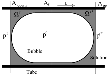
We now consider a single bubble in a capillary of constant section and of perimeter . We assume that the bubble is long enough to create a thin wetting film between the bubble and the wall (see Fig. 9). The problem is not invariant in the direction anymore. However the results of the previous section concern the flow in a small region between the meniscus and the wetting film of extension . These results thus remain valid as long as the tube dimensions are much larger than . Some corrections should nevertheless be considered if the tube has an angular cross-section wong95a ; wong95b ; hazel02 ; cubaud04 .
In Fig. 9, we define three planes perpendicular to the tube section: and are close to the rear and front meniscus, but outside the dynamical meniscus, and is the plane in the middle of the bubble, situated at a distance from each effective contact point between the meniscus and the wetting film. As already discussed for the film profiles in Fig. 5, if the bubble is long enough, the wetting film properties close to are very close to their asymptotic values at , which are identical for the front and films. For menisci in a sliding regime, represents the length of wetting film associated with each meniscus (see section II.1).
The force balance made on the open system (resp. ) constituted by the liquid between (resp. ) and , leads, if momentum fluxes are negligible, to the relation
| (25) |
with the pressure in the bubble and the average pressure, respectively in the section and . In the static case, , and the relation predicts the Laplace under-pressure in the liquid phase. In the dynamical regime, the pressure in the liquid is smaller than the static value for the front meniscus and higher for the rear meniscus, as and (see eqs. (15-17)). Note that the pressure and velocity fields have been obtained in section II by assuming a static pressure in the meniscus. Thus, obviously, the dynamical pressure drop can not be deduced from the pressure distribution plotted on Fig. 7. The dynamical pressure drop appears as a higher order correction that could in principle be re-injected as boundary condition for the film profile, in an iterative scheme park84 .
The total pressure drop for an isolated bubble is . For the case of a cylindrical tube of radius the previous relation simply becomes , so from eq. 18:
| (26) | |||
| (27) | |||
| (28) |
The radius and are identical for the bubble, but differ for the lamella case, discussed below.
This pressure drop, related to the presence of the meniscus, can be compared to the pressure drop induces by the Poiseuille flow in the tube, on both sides of the bubble , with the average liquid velocity and the tube length. For mm and , the meniscus contribution (in the stress free case) is of the same order than the pressure drop induced by a length mm of tube. The local force induced by the meniscus thus strongly dominates the confined diphasic flows, even for relatively distant bubbles.
As discussed in section II.1, the sign of the viscous force is not obvious and may vary for the rear meniscus. An energy balance is made below (for the stress free case), that provides a condition for this sign bretherton61 .
First, the mass balance on or leads to
| (29) |
with the average velocity on the plane or . The energy balance is
| (30) |
The last two terms are respectively the power provided by the interface and the free energy flux exiting the open system . Replacing eq. 25 and eq. 29 into this equation leads to the condition, at dominant order
III.1.2 Lamella
Considering the case of a single lamella, the situation only differs in a few details. The rear meniscus is downstream and the front meniscus upstream. A first consequence of this is that the wetting film downstream can be of arbitrary thickness, and the viscous force corresponding to the adapted rear profile must be used (see fig. 8). A force balance carried out on the open system depicted on Fig. 10 leads to the relation for a cylindrical tube. In contrast with the bubble case, the force balances made for the rear and front menisci involve the surface tension at two distinct points and the difference is thus a priori unknown for the incompressible cases. However, if the external boundary conditions impose the same surface tension at both sides of the lamella, we get the same results as for an isolated bubble, eqs. (26-28).

For lamella, another limitation must be considered, that the meniscus is not pushed by a pressure difference, but pulled by the lamella. The force exerted by the lamella, per unit length in the direction and projected in the direction, is , with the apparent angle between the lamella and the wall, defined in Fig. 10. This force per unit length can not exceed , which thus determines the maximal velocity at which a lamella can be pulled dollet10 :
| (33) |
In the stress free case, this leads to the simple condition , or, for N/m and Pas, m/s. Above this maximal velocity, the lamella breaks. For foam transport in porous media, as used for oil recovery or soil depollution, this dynamical criteria for the lamella stability may be an important issue.
III.2 Bretherton’s pressure derivation for a single bubble
In the specific geometry of a single bubble in a cylindrical tube, the pressure can be obtained using a completely different approach, based on both the asymptotic interface profile shown in Fig. 4 and on the static Laplace relation. This has been derived by Bretherton bretherton61 and in a more rigorous formalism by Park and Homsy park84 .
In the small capillary regime discussed in this paper, the bubble is almost at equilibrium far from the wall. Its shape is thus a spherical cap. As discussed in section I.2, the extrapolation of the outside profile reaches its minimum at the position (positive or negative). The actual radius of curvature of the meniscus is thus slightly smaller than at the front and slightly larger at the rear side. At dominant order in , the dynamical radius of curvature is thus
| (34) |
The Laplace pressure becomes:
| (35) |
This equation is the same as eq. 25 (with ), but this equivalency requires some discussion. In the stress free case, is everywhere equals to . We deduce from eq. 13 that eq. 25 and 35 are identical only if
| (36) |
This relation can easily be proved by integration by parts of , using the relation 6.
For incompressible interfaces, the situation is more subtle, as the correction in the surface tension is of the same order as the correction in the curvature. Thus both need to be taken into account in . The precise value of is given by . Using, as previously, , becomes
| (37) |
Inserting eq. 22 and 36 into this latest expression leads to the same result as given by eq. 27 and 28, thus insuring the consistency of both approaches.
The pressure correction induced by the surface tension variation is not considered in ratulowski90 , thus explaining the different pressure value proposed for the rolling case in Fig. 6 of ratulowski90 . It should also be noted that using a direct analogy of this method to obtain the pressure drop for a lamella, as made in hirasaki85 , leads to a wrong relation between the friction force and the meniscus radius.
IV Boundary conditions for foam flows
IV.1 Film orientation
The friction between a liquid foam and a smooth solid wall is governed by the force exerted on each meniscus in contact with the solid. The model previously developed only considers a meniscus moving in a direction perpendicular to its axis. However, in a foam, the menisci in contact with the wall are oriented in all directions. Comparison of the pressure drops associated with lamellae of different orientations and moving in channel of rectangular section, suggests that only the projected length, in the direction perpendicular to the flow, contributes to the pressure drop cantat04 ; raven06b ; marmottant09 . However, this conjecture, that was natural for a foam having a motion of solid translation, is difficult to extrapolate in a general case. Indeed, during a complex deformation, only the normal velocity of the film is experimentally well defined. It is thus more consistent to assume, as in the viscous froth model kern04 ; grassia08 , that, locally, the force is oriented perpendicular to the meniscus and depends only on the normal velocity. We consider a portion of meniscus of length , that makes an angle with the direction and that moves with the apparent velocity (see Fig. 11). The viscous forces projected in the direction acting on this element are respectively, for the projected length model () and for the non linear viscous force model (),
| (38) |
and
| (39) |
with the viscous force per unit length of meniscus as defined by eq.18.
No clear experimental evidence allows us to discriminate between these two models yet. For the sake of simplicity, we will use eq. 38 in the following section.

IV.2 Influence of the liquid fraction
The effect of the liquid fraction is implicit in the sliding case, through the ratio (see eq. 16). Additionally, the tangential stress between the foam and the wall depends on the total amount of contact lines between the meniscus and the wall, per unit surface, which strongly depends on the bubble volume and on the liquid fraction denkov05 .
IV.2.1 3D dry foams
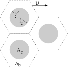
In the dry foam limit, the contact between a bubble and the wall is a polygon of area (see fig. 11). The statistical relation between the bubble radius and its contact area has been investigated numerically in wang09 , and, for a monodisperse foam, the average contact area is found to be . Assuming a hexagonal shape of arbitrary orientation for the contact area, we get the averaged projected length of meniscus per bubble, , as derived in raufaste09 :
| (40) |
Here we neglect the area occupied by the meniscus itself on the solid wall. For slightly larger liquid fractions a correction has been proposed in raufaste09 .
If the interfaces are incompressible, the force depends on and , both of which must be determined as a function of and . In the limit of low liquid fraction, the radius of curvature of the meniscus is well approximated by livre_mousse . Computing the average distance between both sides of a regular hexagon (with 2 edges perpendicular to the velocity direction) we obtain and
| (41) |
Finally, for a monodisperse dry foam, the tangential stress exerted by the wall is
| (42) |
with the expression of the force per unit length of meniscus given by eq. 18, for each kind of interface, and the bubble radius.
IV.2.2 Wet foams
In a wet foam, the bubbles are much less deformed and their shape remains closer to a sphere. The area per bubble on the wall is thus close to . The contact area is a disc of area , as depicted on Fig. 12. The fraction of the wall in contact with the bubbles has been measured by Princen princen85 :
| (43) |
The total amount of meniscus (with its rear and front part) per bubble, projected in the direction perpendicular to the motion, is thus given by and the average wetting film length by . Finally, following the approach proposed by Denkov et al. in denkov05 , the radius of the meniscus is determined from its relation with the osmotic pressure of the foam princen86a :
| (44) |
with the interface curvature, outside the contact area. In this wet regime the bubbles are close to spheres with flat patches, giving . So we can express as and
| (45) |
The osmotic pressures measured by Princen and Kiss princen87 are described by the phenomenological relation
| (46) |
Höhler et al. provided more recent numerical and experimental data for in hohler08 , approximated by the slightly different relation
| (47) |
These relations enable us to predict the tangential stress at the wall as a function of the bubble radius and the liquid fraction in a wet foam:
IV.3 Comparison with some experimental results
IV.3.1 3D Foams
Foam rheological properties are usually investigated with a rheometer in cone/plane geometry. Using smooth plates, there is a velocity range in which the foam is not sheared in bulk and only slips on the bottom plate. The relation between the slip velocity and the stress can thus be deduced, as a function of the bubble size and liquid fraction.
For foaming solutions leading to stress free interfaces, the scaling is well verified denkov05 . However, the theoretical law obtained from eq. 48 and eq. 18 must be corrected by a prefactor close to 4. Similarly high prefactors have also been observed for 2D foam raufaste09 and lamellae cantat04 ; dollet10 .
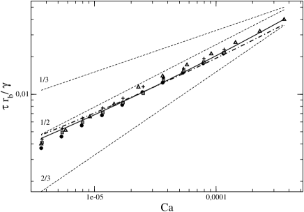
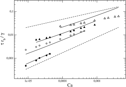
Experimental data have been obtained by Denkov et al. for several foaming solutions of very high interfacial dilatational modulus denkov05 . The results of Section I.3.2 show that the film profiles obtained with this kind of foaming solution are well fitted by the sliding model of interface. We thus compare the experimental stress with the prediction from eq. 48, using the expression of corresponding to the sliding interface (eq. 18):
| (49) |
with . The experimental liquid fraction is . The two models of osmotic pressure eq. 46 and eq. 47 lead respectively to and . Both predictions have been plotted on Fig. 13, keeping as an adjustable parameter. A very good agreement is obtained with and , whereas the theoretical prediction for the prefactor is . Consistently with the observations at the single meniscus scale, the model slightly under-predicts the force. However, the variation with the capillary number is quantitatively reproduced by our model, without adjustable parameter on .
Another set of experimental data obtained by Marze et al., with a solution of Amilite GCK-12, tests the variation of the stress with the liquid fraction in the range marze08 . The data, plotted as a function of the capillary number, are well fitted by power laws, with an exponent that depends on the liquid fraction: for . Qualitatively, the exponent varies continuously from for a dynamic dominated by the meniscus (high liquid fraction) to for a dynamic dominated by the wetting film (moderate liquid fraction), as expected for incompressible interfaces in the sliding regime. A quantitative comparison of these data with the prediction of eq. 49 is shown in Fig. 14 using the expression eq. 47 for the osmotic pressure, as it gives a much better prediction for high liquid fractions than eq. 46. The agreement is very good for the highest liquid fractions but the power law obtained for the smallest value of is not reproduced. In that case, the best agreement is obtained for (using a single adjustable parameter for the four data series).
IV.3.2 2D Foams
The rheological properties of a foam strongly depends on its organization at the bubble scale and the need to observe this local structure is at the origin of the numerous experiments on 2D foams. The bubbles are organized in a single monolayer that is confined either between two glass plates, between the solution and a glass plate or between the solution and the atmosphere. In the first two cases, the viscous friction at the plate plays an important role in the dynamics and is often several order of magnitude higher than the internal viscous force. The stress at the plates has been measured by Raufaste et al. as a function of the capillary number, the meniscus size and the bubble area raufaste09 . All their experimental data are well described by the phenomenological law
| (50) |
with the area per bubble. The velocity power law in 2/3 for the force per unit length of meniscus is not consistent with a dependency on the meniscus radius. However, fitting only the velocity dependency, they found which is between the and exponents. A finite interfacial compressibility may thus be at the origin of this behavior.
V Conclusion
In this paper, we show that a part of the available experimental results on meniscus motion can be explained using very simple assumptions for the interfacial properties. We focus on both the viscous force acting on the moving meniscus and on the induced pressure drop. These are quantities of high practical interest for controlling or predicting bubbles or foam motion close to solid walls. In particular, we establish new predictions for these quantities in the limit of incompressible interfaces. However, wetting film thickness measurements clearly evidence intermediate regimes, between the stress-free interface and the incompressible one stebe91 ; shen02 ; delacotte12 ; cantat12 , and the influence of these on the forces are still unclear. The surfactant concentration at the interface is governed by convective and diffusive processes, as well as adsorption and desorption rates. The interfacial stress is modified by the surfactant’s intrinsic shear and dilatational viscosities and by the variation of the surface tension. More realistic models, taking into account some or all of these interfacial properties, are developed numerically hirasaki85 ; ratulowski90 ; stebe91 ; park92 ; stebe95 ; ramdane97 ; breward02 ; shen02 ; ghadiali03 ; scheid10 . Nevertheless, the rheological properties of the interfaces are not very well characterized at the high extensional rates generated by the meniscus motion and it is often difficult to identify the dominating processes. Moreover, for incompressible or almost incompressible interfaces, the outer flow, far from the dynamical meniscus, may be strongly modified by the moving interface mayer12 . The relevant boundary conditions required to model the interface motion are thus difficult to identify. Different assumptions for the outer flow may lead, in the limit of high surface modulus, to either the rolling or the sliding limiting cases. Consequently, solving the hydrodynamical problem at a larger scale, and not only in the dynamical meniscus domain, is probably unavoidable.
Acknowledgements.
We thank N. Denkov and S. Tcholakova for their experimental data and A. Saint-jalmes, B. Dollet, J. Seiwert, S. Jones and H. A. Stone for their constructive remarks.References
- (1) G. Hirasaki and J. B. Lawson, Mechanisms of foam flow in porous media : apparent viscosity in smooth capillaries, Soc. Pet. Eng. J. 25, p. 176 (1985).
- (2) W. R. Rossen, Theory of mobilization pressure gradient of flowing foams in porous media: I. Incompressible foam, J. Colloid Interface Sci. 136(1), 1 – 16 (1990).
- (3) K. G. Kornev, A. V. Neimark, and A. N. Rozhkov, Foam in porous media: thermodynamic and hydrodynamic peculiarities, Adv. Colloid Interface Sci. 82, 127 – 187 (1999).
- (4) P. Chowdiah, B. R. Misra, J. J. Kilbane, V. J. Srivastava, and T. D. Hayes, Foam propagation through soils for enhanced in-situ remediation, J. Hazard. Mater. 62(3), 265 – 280 (1998).
- (5) J. B. Grotberg, Respiratory fluid mechanics and transport processes, Annu. Rev. Biomed. Eng. 3, 421–457 (2001).
- (6) P. D. Howell, S. L. Waters, and J. B. Grotberg, The propagation of a liquid bolus along a liquid lined flexible tube, J. Fluid Mech. 406, 309 (2000).
- (7) C. N. Baroud, F. Gallaire, and R. Dangla, Dynamics of microfluidic droplets, Lab Chip 10, 2032–2045 (2010).
- (8) D. Quéré, Fluid coating on a fiber, Annu. Rev. Fluid. Mech. 31(1), 347–384 (1999).
- (9) R. Höhler and S. Cohen-Addad, Rheology of liquid foam, J. Phys.: Condens. Matter 17, R1041–R1069 (2005).
- (10) I. Cantat, S. Cohen-Addad, F. Elias, F. Graner, R. Höhler, O. Pitois, F. Rouyer, and A. Saint-Jalmes, Les mousses. Structure et dynamique, BELIN, Paris, 2010.
- (11) L. Landau and B. Levich, Dragging of a liquid by a moving plate, Acta Physicochim. USSR 17, 42 (1942).
- (12) B. V. Derjaguin, Thickness of liquid layer adhering to walls of vessels on their emptying, Acta physicochim URSS 20, 349 (1943).
- (13) F. P. Bretherton, The motion of long bubbles in tubes, J. Fluid Mech. 10, 166–188 (1961).
- (14) C.-W. Park and G. M. Homsy, Numerical simulation of a concentrated emulsion in shear flow, J. Fluid Mech. 139, 291–308 (1984).
- (15) F. Fairbrother and A. E. Stubbs, Studies in Electro-Endosmosis VI. The ”Bubble Tube” Method of Measurement, J. Chem. Soc. 1, 527 (1935).
- (16) G. Taylor, Deposition of a viscous fluid on the wall of a tube, J. Fluid Mech. 10, 161 (1961).
- (17) J.-D. Chen, Measuring the film thickness surrounding a bubble inside a capillary, J. Colloid Interface Sci. 109(2), 341 – 349 (1986).
- (18) L. W. Schwartz, H. M. Princen, and A. D. Kiss, On the motion of bubbles in capillary tubes, J. Fluid Mech. 172, 259 (1986).
- (19) P. Aussillous and D. Quéré, Quick deposition of a fluid on the wall of a tube, Physics of Fluids 12, 2367–2371 (2000).
- (20) J. Emile, F. Casanova, H. Tabuteau, and O. Emile, Profile of the liquid film wetting a channel, Appl. Phys. Lett. 100, 074107 (2012).
- (21) T. S. Chan, J. H. Snoeijer, and J. Eggers, Theory of the forced wetting transition, Phys. Fluids 624, 072104 (2012).
- (22) T. Cubaud and C.-M. Ho, Transport of bubbles in square microchannels, Phys. Fluids 16, 4575–4585 (2004).
- (23) M. J. Fuerstman, A. Lai, M. E. Thurlow, S. S. Shevkoplyas, H. A. Stone, and G. M. Whitesides, The pressure drop along rectangular microchannels containing bubbles, Lab Chip 7, 1479–1489 (2007).
- (24) I. Cantat, N. Kern, and R. Delannay, Dissipation in foam flowing through narrow channels, EPL 65, 726–732 (2004).
- (25) E. Terriac, J. Etrillard, and I. Cantat, Viscous force exerted on a foam at a solid boundary : influence of the liquid fraction and of the bubble size, EPL 74, 909–915 (2006).
- (26) B. Dollet and I. Cantat, Deformation of soap films pushed through tubes at high velocity, J. Fluid Mech. 652, 529–539 (2010).
- (27) A. Bazilevsky and A. Rozhkov, Motion of a foam lamella in a circular channel under a relaxing small pressure jump, Colloids Surf. A 414(0), 457 – 465 (2012).
- (28) C. Raufaste, A. Foulon, and B. Dollet, Dissipation in quasi-two-dimensional flowing foams, Phys. Fluids 21, 053102 – 053110 (2009).
- (29) N. D. Denkov, V. Subramanian, D. Gurovich, and A. Lips, wall slip and viscous dissipation in sheared foams : Effect of surface mobility, Colloids Surf. A 263, 129 (2005).
- (30) S. Marze, D. Langevin, and A. Saint-Jalmes, Aqueous Foam Slip and Shear Regimes Determined by Rheometry and Multiple Light Scattering, J. Rheol. 52, 1091 (2008).
- (31) D. A. Reinelt and P. G. Saffman, The Penetration of a Finger into a Viscous Fluid in a Channel and Tube, SIAM Journal on Scientific and Statistical Computing 6, 542–561 (1985).
- (32) D. A. Reinelt, The rate at which a long bubble rises in a vertical tube, J. Fluid Mech. 175, 557–565 (1987).
- (33) J. Ratulowski and H.-C. Chang, Transport of gas bubbles in capillaries, Phys. Fluids A 10, 1642 (1989).
- (34) M. J. Martinez and K. S. Udell, Axisymmetric creeping motion of drops through circular tubes, J. Fluid Mech. 210, 565–591 (1990).
- (35) M. D. Giavedoni and F. A. Saita, The axisymmetric and plane cases of a gas phase steadily displacing a Newtonian liquid–A simultaneous solution of the governing equations, Phys. Fluids 9, 2420–2428 (1997).
- (36) M. Heil, Finite Reynolds number effects in the Bretherton problem, Phys. Fluids 13, 2517 (2001).
- (37) A. L. Hazel and M. Heil, The steady propagation of a semi infinite bubble into a tube of elliptical or rectangular cross-section, J. Fluid Mech. 470, 91 (2002).
- (38) A. Saugey, W. Drenckhan, and D. Weaire, Wall slip of bubbles in foams, Phys. Fluids 18, 053101 (2006).
- (39) H. Fujioka, S. Takayama, and B. Grotberg, Unsteady propagation of a liquid plug in a liquid-lined straight tube, Phys. Fluids 20, 062104 (2008).
- (40) B. Derjaguin, Die elastischen Eigenschaften der Schäume, Kolloid Z. 64, 1 (1933).
- (41) L. H. Tanner, The spreading of silicone oil drops on horizontal surfaces, J. Phys. D: Appl. Phys 12, 1473 (1979).
- (42) A. Q. Shen, B. Gleason, G. H. McKinley, and H. A. Stone, Fiber coating with surfactant solutions, Phys. Fluids 14, 4055 (2002).
- (43) M. D. Giavedoni and F. A. Saita, The rear meniscus of a long bubble steadily displacing a Newtonian liquid in a capillary tube, Phys. Fluids 11, 786 (1999).
- (44) B. Duffy and S. Wilson, A third-order differential equation arising in thin-film flows and relevant to Tanner’s Law, Applied Mathematics Letters 10(3), 63 – 68 (1997).
- (45) R. Chebbi, Deformation of advancing gas-liquid interfaces in capillary tubes, J. Colloid Interface Sci. 265, 166 (2003).
- (46) P. G. de Gennes, Wetting: statics and dynamics, Rev. Mod. Phys. 57(3), 827–863 (1985).
- (47) J. Bico and D. Quéré, Falling Slugs, J. Colloid Interface Sci. 243(1), 262 – 264 (2001).
- (48) S. L. Cormier, J. D. McGraw, T. Salez, and E. R. K. Dalnoki-Veress, Beyond Tanner’s Law: Crossover between Spreading Regimes of a Viscous Droplet on an Identical Film, Phys. Rev. Lett. 109, 154501 (2012).
- (49) B. Scheid, J. Delacotte, B. Dollet, E. Rio, F. Restagno, E. A. van Nierop, I. Cantat, D. Langevin, and H. A. Stone, The role of surface force rheology in liquid film formation, EPL 90, 24002 (2010).
- (50) H. C. Mayer and R. Krechetnikov, Landau-Levich flow visualization: Revealing the flow topology responsible for the film thickening phenomena, Phys. Fluids 24, 052103 (2012).
- (51) N. D. Denkov, S. Tcholakova, K. Golemanov, V. Subramanian, and A. Lips, Foam-wall friction: Effect of air volume fraction for tangentially immobile bubble surface, Colloids Surf. A 282, 329–347 (2006).
- (52) C. W. Park, Influence of soluble surfactants on the motion of a finite bubble in a capillary tube, Phys. Fluids 4, 2335–2347 (1992).
- (53) S. P. Meeker, R. T. Bonnecaze, and M. Cloitre, Slip and flow in soft particle pastes, Phys. Rev. Lett. 92, 198302 (2004).
- (54) G. F. Teletzke, H. T. Davis, and L. Scriven, Wetting hydrodynamics, Rev. Phys. Appl. 23(6), 989–1007 (1988).
- (55) D. Quéré, J.-M. di Meglio, and F. Brochard-Wyart, Making van der Waals Films on Fibers, EPL 10(4), 335 (1989).
- (56) D. Quéré and A. de Ryck, Le mouillage dynamique des fibres, Ann. Phys. 23, 1–151 (1998).
- (57) I. Cantat and B. Dollet, Liquid films with high surface modulus moving in tubes: dynamic wetting film and jumpy motion, Soft Mat. 8, 7790 (2012).
- (58) H. Wong, C. J. Radke, and S. Morris, The motion of long bubbles in polygonal capillaries. Part 1. Thin films, J. Fluid Mech. 292, 71 (1995).
- (59) H. Wong, C. J. Radke, and S. Morris, The motion of long bubbles in polygonal capillaries. Part 2. drag, fluid pressure and fluid flow, J. Fluid Mech. 292, 95 (1995).
- (60) J. Ratulowski and H.-C. Chang, Marangoni effects of trace of impurities on the motion of long gas bubbles in capillaries, J. Fluid Mech. 210, 303–328 (1990).
- (61) J.-P. Raven and P. Marmottant, Periodic microfluidic bubbling oscillator : insight into the stability of two-phase microflows, Phys. Rev. Lett. 97, 154501 (2006).
- (62) P. Marmottant and J.-P. Raven, Microfluidics with foams, Soft Mat. 5, 3385–3388 (2009).
- (63) N. Kern, D. Weaire, A. Martin, S. Hutzler, and S. J. Cox, The two dimensionnal viscous froth model for foam dynamics, Phys. Rev. E 70, 041411 (2004).
- (64) P. Grassia, G. Montes-Atenas, L. Lue, and T. E. Green, A foam film propagating in a confined geometry: Analysis via the viscous froth model, Eur. Phys. J. E 25, 39–49 (2008).
- (65) Y. Wang and S. J. Neethling, The relationship between the surface and internal structure of dry foam, Colloids Surf. A 339(1-3), 73 – 81 (2009).
- (66) H. M. Princen, Rheology of foams and highly concentrated emulsions. II Experimental study of the yield stress and wall effects for concentrated oil-in-water emulsions, J. Colloid Interface Sci. 105, 150 (1985).
- (67) H. M. Princen, Osmotic pressure of foams and highly concentrated emulsions. I. Theoretical considerations, Langmuir 2(4), 519–524 (1986).
- (68) H. M. Princen and A. Kiss, Osmotic pressure of foams and highly concentrated emulsions. 2. Determination from the variation in volume fraction with height in an equilibrium column, Langmuir 3, 36–41 (1987).
- (69) R. Höhler, Y. Y. C. Sang, E. Lorenceau, and S. Cohen-Addad, Osmotic Pressure and Structures of Monodisperse Ordered Foam, Langmuir 24, 418–425 (2008).
- (70) K. J. Stebe, S.-Y. Lin, and C. Maldarelli, Remobilizing surfactant retarded fluid particle interfaces. I. Stress-free conditions at the interfaces of micellar solutions of surfactants with fast sorption kinetics, Phys. Fluids 3, 3 (1991).
- (71) J. Delacotte, L. Montel, F. Restagno, B. Scheid, B. Dollet, H. A. Stone, D. Langevin, and E. Rio, Plate Coating: Influence of Concentrated Surfactants on the Film Thickness, Langmuir 28(8), 3821–3830 (2012).
- (72) K. J. Stebe and D. Barthès-Biesel, Marangoni effects of adsorption/desorption controlled surfactants on the leading end of an infinitely long bubble in a capillary, J. Fluid Mech. 286, 25–48 (1995).
- (73) O. Ou Ramdane and D. Quéré, Thickening Factor in Marangoni Coating, Langmuir 13(11), 2911–2916 (1997).
- (74) C. J. W. Breward and P. D. Howell, The drainage of a foam lamella, J. Fluid Mech. 458, 379–406 (2002).
- (75) S. N. Ghadiali and D. P. Gaver, The influence of non-equilibrium surfactant dynamics on the flow of a semi-infinite bubble in a rigid cylindrical capillary tube, J. Fluid Mech. 478, 165–196 (2003).