Spin Caloritronics in graphene with Mn
Abstract
We show that graphene with Mn adatoms trapped at single vacancies feature spin-dependent Seebeck effect, thus enabling the use of this material for spin caloritronics. A gate potential can be used to tune its thermoelectric properties in a way it presents either a total spin polarized current, flowing in one given direction, or currents for both spins flowing in opposite directions without net charge transport. Moreover, we show that the thermal magnetoresistance can be tuned between -100% and +100% by varying a gate potential.
pacs:
72.20.Pa, 72.80.Vp, 85.75.-d, 72.25.BaThe field of spin caloritronics deals with the interaction of spin and heat currents, that is, the coupling between spintronics and thermoelectricsBauer, Saitoh, and van Wees (2012). GrapheneNovoselov et al. (2004) is a potential candidate material for spintronic devices Karpan et al. (2007); Tombros et al. (2007) due to its long mean free path and weak spin-orbit coupling. Furthermore, it has been shown that graphene has potential for thermoelectric devices, both theoretically Dragoman and Dragoman (2007); Zhou et al. (2012) and experimentallyZuev, Chang, and Kim (2009); Basko (2011); Wu et al. (2011). Therefore, at least in principle, graphene is a good candidate for spin caloritronics. Devices made of graphene nanoribbons with zigzag edges have already been proposed to this end Zeng, Feng, and Liang (2011a, b). Bi-dimensional graphene itself, although a good conductor for spin polarized currents, is spin degenerate, so it cannot be used as a source for spin polarized currents. One way to lift its spin degeneracy that has been investigated recently is to dope graphene with metal adatoms Cretu et al. (2010); Lima, da Silva, and Fazzio (2011); Santos, Ayuela, and Sánchez-Portal (2010); Cao et al. (2010); Santos, Sánchez-Portal, and Ayuela (2010); Krasheninnikov et al. (2009). Although their tendency is to diffuse and to form clusters, they can be trapped in defects like single vacancies (SV), where they are highly stableLima, da Silva, and Fazzio (2011); Tang, Yang, and Dai (2011). SV defects in graphene can be created by ionWang et al. (2012) or electronCretu et al. (2010) irradiation, and, in the latter case, the use of focused beams allows sub-nanometer spatial controlRodriguez-Manzo and Banhart (2009).
It has already been shown by some of us that spin polarized currents appear in graphene doped with transition metals if spin-split localized levels that strongly hybridize with the -bands of graphene are present close to the Fermi level ()Lima, da Silva, and Fazzio (2011). One particular feature that distinguishes the atom trapped in SV (Mn@SV) from other configurations is its particular band structure, where there are occupied states with majority spin, and unoccupied states with minority spin, both almost symmetrically positioned with respect to Lima, da Silva, and Fazzio (2011); Krasheninnikov et al. (2009); Santos, Ayuela, and Sánchez-Portal (2010). These localized states generate valleys with majority (minority) spin below (above) in the transmission probability. Moreover, this transmission probability (and thus the current) can be tuned by a gate potentialLima, da Silva, and Fazzio (2011).
In this work, we calculate the thermoelectric properties and the spin-polarized currents of Mn@SV aiming to investigate its suitability for spin caloritronics. We show that i) the ferromagnetic (F) alignment is energetically favorable for Mn-Mn distances greater than Å, whereas the anti-ferromagnetic (AF) alignment occurs for shorter distances; ii) it is possible to turn the current for a given spin channel arbitrarily small, or to have the up- and down-spin currents canceling each other by varying the gate voltages (); iii) the thermal magnetoresistance can be tuned to any desirable (from to ) value by changing .
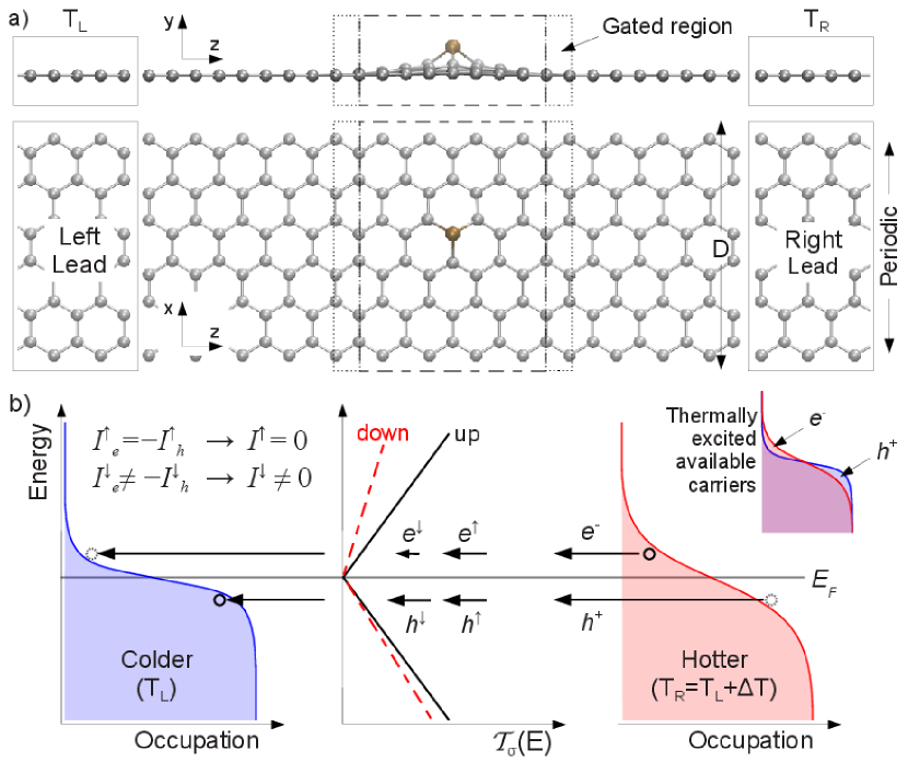
Our calculations have been performed with non-equilibrium Green’s functions coupled to density functional theory (NEGF+DFT). First, the geometries, comprised of a Mn@SV in a graphene supercell (), were fully relaxed with a force criterion of 0.02 eV/Å using the siesta codeArtacho et al. (1999). Here, is the distance between a atom and its lateral periodic image, as shown in Fig. 1a. Then, we calculated the transmittances using the transampa2 codeNovaes, da Silva, and Fazzio (2006); *transampa2; *GPU. The electrodes were considered to be semi-infinite pristine graphene sheets. In all calculations we used the Perdew-Burke-Ernzerhof generalized gradient approximationPerdew, Burke, and Ernzerhof (1996) for the exchange-correlation functional, norm-conserving pseudopotentialsTroullier and Martins (1991) and a double- polarized basis. We used an energy mesh cutoff of 300 Ry and a -point sampling, in the Monkhorst-Pack Monkhorst and Pack (1976) scheme, to integrate the Brillouin zone. For the electronic transport calculations we employed 200 -points (3000 for the PDOS). The gate potential was simulated by adding a smooth electrostatic potential to the Hamiltonian in a finite region (a slab) containing the Mn@SV in the self-consistent cycle, thus allowing screening effects by charge rearrangementLima, da Silva, and Fazzio (2011); Gat . A vacuum layer of 20 Å was used to avoid spurious interactions between periodical images in the direction perpendicular to the graphene plane ( in Fig. 1a).
In the Landauer-Büttiker formalism, the current is given byBüttiker et al. (1985); *Buttiker
| (1) |
where is the spin, is the electron charge, is the Planck constant, is the spin resolved transmittance function, which depends on the gate voltage ; is the Fermi-Dirac distribution function, is the chemical potential of the electrodes and is the temperature of the left(right) lead.
When the contacts are at different temperatures, the resultant unbalance in the density of thermally excited charge carriers, given by , allows electrons () and holes () to be available to flow from the hot to the cold electrode, as shown in Fig. 1b. However, in order to the and currents not to cancel each other and a net current to be established, must be asymmetric around , that is, the transmittance for () and () needs to be different, otherwise .
The Seebeck coefficient, also named thermoelectric power, is a measure of the voltage induced by a temperature difference and is defined as . In the limiting case of and (the linear regime) an expression for can be derived from an expansion of Eq. (1), given bySivan and Imry (1986)
| (2) |
where is the average temperature between the contacts. Notice that the numerator of Eq. (2) (and therefore ) is a measure of the local asymmetry of around in an energy range given by (whose width, in turn, is determined by ). We also see from Eq. (2) that if is greater (smaller) than (near ) the resultant will be negative (positive).
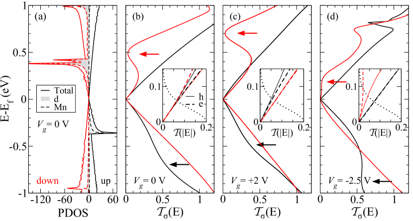
In Fig. 2a we show the projected density of states (PDOS) for the whole system, for the Mn atoms, and for the orbitals ( and Å). As can be seen, the Mn@SV shows occupied (empty) localized levels nearly symmetrically located at approximately eV from for the () spins. These levels give origin to valleys in , indicated by arrows in Fig. 2b, which also affect the slope of the transmittance near . Positive (Fig. 2c) raises the levels, moving the () spin valleys towards (away from) . On the other hand, negative (Fig. 2d) lowers them, moving the () spin valleys away from (towards) . In the insets of Figs. 2b-d, the asymmetry in between () and () close to is shown in more detail. For both spin channels are symmetric for eV. However, for eV, (resulting in ) and (resulting in ). It is also interesting to note that, in this case, , which means that (approximately) there is not a net charge transport because cancels with , but there is spin transport because this canceling out is not from charge carriers of the same spin. For V, the spin valley is shifted away from , rendering symmetric, and then, . The spin valley is closer to , diminishing for , which makes , and thus (this case is similar to the one depicted in Fig. 1b). An opposite behavior happens for V: the spin valley moves away from , rendering symmetric between and (giving ); whereas the spin valley moves closer to , yielding highly asymmetric, lowering in comparison to (resulting in ).
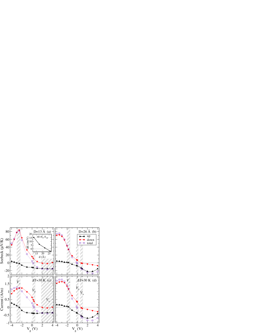
The total energy difference between the ferromagnetic and the anti-ferromagnetic alignment as a function of the Mn-Mn distance is shown in the inset of Fig. 3a. To perform this simulation we laterally duplicate the geometry presented in Fig. 1a, obtaining a supercell with two Mn@SV and . For Å the AF configuration is energetically favorable, indicating that a magnetic field is necessary to obtain the F configuration. On the other hand, for Å the F alignment is the most favorable one. Note that only the F alignment has the spin unbalancing required to generate spin-polarized currents. Thus, all results presented in this work, except the thermally induced magnetoresistance, consider this magnetic alignment.
In Fig. 3 we show how the Seebeck coefficient and the thermally induced current vary with for and Å. For the larger , the dispersion (and the broadening) of the localized levels get smaller, resulting in narrower valleys in Lima, da Silva, and Fazzio (2011). However, the qualitative behavior is very similar for both cases. As discussed before, shifts the valleys in , which allows one to tune the asymmetry in and thus, to tune and . From Fig. 3 it can be easily seen that there are three ranges of (that we name , and ), where the system can be tuned into three distinctive behaviors: (i) at , and ( and , see Fig. 2d); and there is only flowing; (ii) close to zero gate, for , (, see Fig. 2b); in this case the system presents counter propagating spin currents without net charge transport; and, (iii) at , and ( and , see Fig. 2c); and there is only flowing. For Å, these ranges are depicted in Fig. 3.
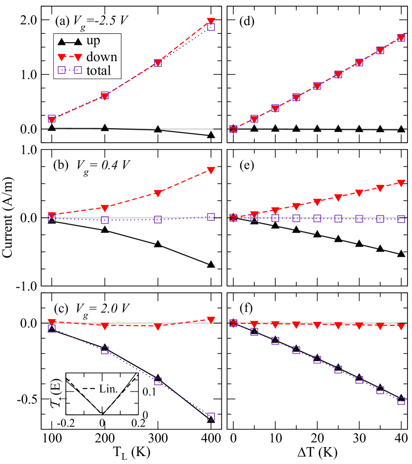
To investigate if the behaviors discussed above are robust under temperature changes, we calculated the current at different and for particular values of within , and with =13.0 Å. In Figs. 4a-c we show as a function of for constant K, and in Figs. 4d-f as a function of for fixed K. The temperature of the right contact was always varied as . When raises (constant ), broadens and some charge carriers are excited to higher energies. This, combined with the deviation from linearity of for high enough (see the inset in Fig. 4c) results in the non linear trend of with . When varies (fixed ), the width of remains nearly constant but its amplitude grows linearly, giving . Thus, the gate voltages necessary to achieve the situations (i),(ii) and (iii) are robust under changes in the temperature.
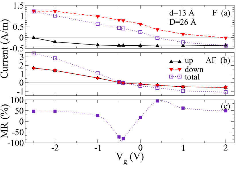
We also calculated the thermoelectric currents for the F and AF alignments, shown in Fig. 5a and Fig. 5b, respectively. The F alignment exhibits a pronounced spin-polarization in the current, whereas for the AF configuration there is no spin-polarization in the current, as expected due to the spin degenerated spectrum.
The thermally induced magneto-resistance (MR) is given by:
| (3) |
This quantity depends only on the total currents for the F (AF) alignments. Colossal MR are obtained when either or are approximately zero. As seen in Fig 5, in this system it is possible to obtain both situations by varying . For V , leading to , whereas for V, , leading to . Thus, by varying within this region it is possible to control the MR to any desirable value between -100% and +100%, as shown in Fig. 5c.
Summarizing, the peculiar electronic structure of Mn@SV, with up and down states positioned almost symmetrically with respect to the Fermi level allows a high flexibility of the spin-dependent thermoelectric properties. The electron-hole asymmetry of , and consequently the spin dependent Seebeck coefficient can be controlled by a gate voltage (), leading to a suitable system for usage in spin caloritronics.
Acknowledgements.
We would like to thank A. R. Rocha for a critical reading of an earlier version of this manuscript. This work has received financial support from the brazilian agencies CNPq, INCT-Nanomateriais de Carbono and FAPESP. The calculations have been performed at CENAPAD-SP.References
- Bauer, Saitoh, and van Wees (2012) G. E. W. Bauer, E. Saitoh, and B. J. van Wees, Nature Mater. 11, 391 (2012).
- Novoselov et al. (2004) K. S. Novoselov, A. K. Geim, S. V. Morozov, D. Jiang, Y. Zhang, S. V. Dubonos, I. V. Grigorieva, and A. A. Firsov, Science 306, 666 (2004).
- Karpan et al. (2007) V. M. Karpan, G. Giovannetti, P. A. Khomyakov, M. Talanana, A. A. Starikov, M. Zwierzycki, J. van den Brink, G. Brocks, and P. J. Kelly, Phys. Rev. Lett. 99, 176602 (2007).
- Tombros et al. (2007) N. Tombros, C. Jozsa, M. Popinciuc, H. T. Jonkman, and B. J. van Wees, Nature 448, 571 (2007).
- Dragoman and Dragoman (2007) D. Dragoman and M. Dragoman, Appl. Phys. Lett. 91, 203116 (2007).
- Zhou et al. (2012) B. Zhou, B. Zhou, Z. Liu, and G. Zhou, J. Appl. Phys. 112, 073712 (2012).
- Zuev, Chang, and Kim (2009) Y. M. Zuev, W. Chang, and P. Kim, Phys. Rev. Lett. 102, 096807 (2009).
- Basko (2011) D. Basko, Science 334, 610 (2011).
- Wu et al. (2011) X. Wu, Y. Hu, M. Ruan, N. K. Madiomanana, C. Berger, and W. A. de Heer, Appl. Phys. Lett. 99, 133102 (2011).
- Zeng, Feng, and Liang (2011a) M. Zeng, Y. Feng, and G. Liang, Nano Lett. 11, 1369 (2011a).
- Zeng, Feng, and Liang (2011b) M. Zeng, Y. Feng, and G. Liang, Appl. Phys. Lett. 99, 123114 (2011b).
- Cretu et al. (2010) O. Cretu, A. V. Krasheninnikov, J. A. Rodríguez-Manzo, L. Sun, R. M. Nieminen, and F. Banhart, Phys. Rev. Lett. 105, 196102 (2010).
- Lima, da Silva, and Fazzio (2011) M. P. Lima, A. J. R. da Silva, and A. Fazzio, Phys. Rev. B 84, 245411 (2011).
- Santos, Ayuela, and Sánchez-Portal (2010) E. J. G. Santos, A. Ayuela, and D. Sánchez-Portal, New J. Phys. 12, 053012 (2010).
- Cao et al. (2010) C. Cao, M. Wu, J. Jiang, and H.-P. Cheng, Phys. Rev. B 81, 205424 (2010).
- Santos, Sánchez-Portal, and Ayuela (2010) E. J. G. Santos, D. Sánchez-Portal, and A. Ayuela, Phys. Rev. B 81, 125433 (2010).
- Krasheninnikov et al. (2009) A. V. Krasheninnikov, P. O. Lehtinen, A. S. Foster, P. Pyykkö, and R. M. Nieminen, Phys. Rev. Lett. 102, 126807 (2009).
- Tang, Yang, and Dai (2011) Y. Tang, Z. Yang, and X. Dai, J. Chem. Phys. 135, 224704 (2011).
- Wang et al. (2012) H. Wang, Q. Wang, Y. Cheng, K. Li, Y. Yao, Q. Zhang, C. Dong, P. Wang, U. Schwingenschlögl, W. Yang, and X. X. Zhang, Nano Lett. 12, 141 (2012).
- Rodriguez-Manzo and Banhart (2009) J. A. Rodriguez-Manzo and F. Banhart, Nano Lett. 9, 2285 (2009).
- Artacho et al. (1999) E. Artacho, D. Sánchez-Portal, P. Ordejón, A. García, and J. M. Soler, Phys. Status Solidi (b) 215, 809 (1999).
- Novaes, da Silva, and Fazzio (2006) F. D. Novaes, A. J. R. da Silva, and A. Fazzio, Braz. J. Phys. 36, 799 (2006).
- Padilha et al. (2011) J. E. Padilha, M. P. Lima, A. J. R. da Silva, and A. Fazzio, Phys. Rev. B 84, 113412 (2011).
- (24) The code has been modified to allow the use of graphical processing units (GPUs).
- Perdew, Burke, and Ernzerhof (1996) J. P. Perdew, K. Burke, and M. Ernzerhof, Phys. Rev. Lett. 77, 3865 (1996).
- Troullier and Martins (1991) N. Troullier and J. L. Martins, Phys. Rev. B 43, 1993 (1991).
- Monkhorst and Pack (1976) H. J. Monkhorst and J. D. Pack, Phys. Rev. B 13, 5188 (1976).
- (28) This potential consists of a plateau, for , represented by a dashed line in Fig. 1a, with smooth sinusoidal steps with width , indicated by the dotted lines in Fig. 1a. elsewhere. In the calculations we defined the gated region trough Å, Å and Å.
- Büttiker et al. (1985) M. Büttiker, Y. Imry, R. Landauer, and S. Pinhas, Phys. Rev. B 31, 6207 (1985).
- Büttiker (1986) M. Büttiker, Phys. Rev. Lett. 57, 1761 (1986).
- Sivan and Imry (1986) U. Sivan and Y. Imry, Phys. Rev. B 33, 551 (1986).