IEEE 802.15.4 transceiver for the 868/915 MHz band using Software Defined Radio
Abstract
This paper reports an implementation of the PHY specifications of the IEEE 802.15.4 standard for the frequency band 868/915 MHz on a Software Defined Radio (SDR) platform. This standard is defined for low power, low data rate and low cost wireless networks. These specifications are used by the Zigbee technology for various applications such as home automation, industry monitoring or medical surveillance. Several hardware PHY 868/915 MHz band IEEE 802.15.4 transceiver implementations have been already reported on ASIC and FPGA [1] [2]. SDR offers one possibility to realize a transceiver with high flexibility and reconfigurability [3]. The whole –transmitter and receiver– chain has been defined in software using the GNU Radio software project [4] and the USRP (Universal Software Radio Peripheral) platform from Ettus Research [5]. Two new blocks have been added to the GNU Radio project, one for the Direct Sequence Spread Spectrum and the second for the reconstruction of the packets. The experimentations have been performed in a noisy environment and the PER, BER and SNR have been computed. The obtained results are coherent with what can be expected from the theory.
Index Terms:
Wireless communications, Software Defined Radio, IEEE 802.15.4, GNU Radio.I Introduction
Most of the standards and protocols of lower layers of wireless transmissions (AM, FM, IEEE 802.11, IEEE 802.15.1, IEEE 802.15.4. etc.) are mainly implemented in hardware (HW). This lack of reconfigurability makes the adaptation to varying radio resources difficult, especially when multiple standards need to be often switched in order to take advantage of the scarce radio resources available. The purpose of Software Defined Radio (SDR) is to avoid these drawbacks of traditional wireless communications and replace the hardware equipment by software. The huge advantage of SDR platform lies in its flexibility, its multi-functionality and its low development cost. The reconfigurability of the platform ensures the reusability of the hardware [3], thus minimizing the design complexity of new RF terminals.
The ideal SDR allows the analog-to-digital (ADC) and digital-to-analog (DAC) conversion to be as close as possible to the antenna [mistola93], eliminating the need of high-frequency radio subsystems. Subsequently, the CPU executes the software (SW) subsystem of the SDR, all signal processing operations are accomplished by SW. Unfortunately, today’s technology is neither cost-effective for direct ADC conversion from the antenna nor enough power full to compute GSPS (Giga Samples-per-Second) in real-time. Therefore, the typical SDR platform available today uses HW high-frequency radio front-end, the SDR part being implemented in the baseband only. The HW supporting the SDR platform is typically based on FPGAs or DSPs (Digital Signal Processors) [6].
GNU Radio [7] and OSSIE [8] (Open-Source Software Communication Architecture Implementation Embedded) are the two open source software subsystems for the USRP (Universal Software Radio Peripheral) SDR from Ettus Research [5]. The USRP HW is available in different versions. In our implementation we used the USRP1 HW, featuring a sampling rate of 128 MSPS (Mega Samples-per-Second) for the transmitter and 64 MSPS for the receiver. By addition of different daughter-boards, the baseband signal can be transposed in frequency bands up to 6000 MHz. The USRP1 HW platform proves to be also cost-effective, compared to its competitors (Microsoft’s SORA and Datasoft’s Typhoon).
The IEEE 802.15.4 [9] standard defines the physical and link layers for low-rate Wireless Personnel Area Networks (LR-WPAN), used in wireless sensor networks applications with strong energy consumption constraints. The physical layer comprises three principal frequency bands allowing 49 channels: 16 channels in the 2450 MHz for the ISM (Industrial Scientific Medical) band, 30 for North America and 3 channels in the 868 MHz band for Europe [9]. The band of 2450 MHz operates at law data rates of 250 kb/s while the bands of 915 MHz and 868 MHz operate at 40 kb/s and 20 kb/s respectively.
A number of hardware implementations of the IEEE 802.15.4 have been reported on ASICs or FPGAs [1], [2], but they do not allow us to control the flexibility and the ability of all software stack layers. The first software implementation of the IEEE 802.15.4 using the GNURadio environment for the 2450 MHz band was reported in [10]. In wireless sensor networks, the transceiver in the 868/915 MHz band is more suitable when low data rate transmission are used between sensor nodes. Furthermore it presents a longer range than that of the 2450 MHz band for a given link budget. The objective of our work is to implement the specifications of the IEEE 802.15.4 standard for the 868/915 MHz band, which is not yet reported in the literature.
Our software transceiver was developed by closely following the IEEE 802.15.4 specifications for the 868/915 MHz bands. The implementation is similar to the one of 2450 MHz band presented in [SchmidDS06], [10]. To evaluate the transmitter/receiver performances, the BER (Bit Error Rate) and SNR (Signal-to-Noise Ratio) have been computed by changing the input power signal at the transmitter.
The rest of the paper is organized as follows. Section II presents a description of the SDR platform used. In Section III, we present the description of the developed transmitter/receiver chain. Section IV discusses the experimentations and the obtained results. Finally, in Section V we formulate some concluding remarks.
II USRP and GNU Radio
In the following two subsections we describe briefly the USRP1 HW [5], used in our implementation as well as the GNU Radio [4] toolkit.
II-A Universal Software Radio Peripheral
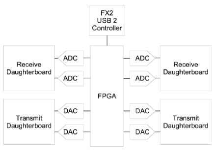
The USRP1 HW consists of a motherboard and optional add-on RF daughterboards. It is connected to a host computer via USB 2.0. The USRP’s motherboard supports up to four daughterboards: two for transmission (TX) and two for reception (RX). The motherboard has four 12-bits ADCs (with a maximum sampling rate of 64 MSPS), four 14-bit DACs (with a maximum conversion rate of 128 MSPS), and an Altera FPGA for simple but high-speed operations such as up-conversion, down-conversion, interpolation, and decimation [5]. The ADCs and DACs allow us to receive baseband signals up to 32 MHz and are able to generate baseband signals up to 50 MHz. Unfortunately, the USB tunnel limits these performances to 8 MHz. The USRP1 provides buffer in both the USB controller and the FPGA at 2 KB and 4 KB respectively. Fig. 1 depicts the USRP1 blocks from the motherboard.
 |
II-B GNU Radio
GNU Radio is an open source project toolkit for building software radios that run on host computers [4]. It provides signal processing blocks for modulation, demodulation, filtering and various Input/Output operations. New blocks can be easily added to the toolkit. The software radio platform is created by connecting these blocks to form a flowgraph. The blocks are written in C++ and they are connected through a Python script. The Verilog HDL layer is dedicated to configure the FPGA.
The advantage of Python in connecting these processing blocks is that it allows the data flow to be at maximum rate, without being interpreted. The integration of the C++ blocks into the scripting language is provided by the SWIG (Simplified Wrapper and Interface Generator), which is an interface compiler. Many signal processing blocks are available to the GNU Radio community to facilitate the development. To create a flow graph we can proceed by the graphical interface called gnuradio-companion or directly through the python code. The C++ blocks are described by the XML code to facilitate the use and the visibility of the block chains, the XML is interpreted to the python code by the cheetah tools111http://www.cheetahtemplate.org/ . In Fig. 2 we depict the programming language layers of the GNU Radio.
 |
III Transceiver Description
 |
The IEEE 802.15.4 [9] standard is the definition of wireless physical (PHY) and medium access control (MAC) protocols for low-data rate and low power applications. It specifies two families of bands: the first one is centered at 868 and 915 MHz with 20 and 40 kbps, the second one at 2450 MHz with 250 kbps.
The specifications from [9] define the use of different modulation techniques and data rate for the specified channels. The D-BPSK (Differential Binary Phase Shift Keying) is one of the modulation techniques used in the 915/868 MHz. The symbol spreading is the Direct Sequence Spread Spectrum (DSSS), in which each symbol is represented by a Pseudo Noise sequence of 15 chips. The chips are modulated/demodulated by the D-BPSK encoding/decoding at rates of 300 kchips/s and 600 kchips/s for the 868 MHz and 915 MHz bands respectively.
III-A Transmitter
Our transmitter comprises eight processing blocks, as depicted in Fig. 3. The definition of the packet messages is based on that of the IEEE 802.15.4 standard. The packet format is detailed in Fig. 4. At the output of the transmitter, the maximum packet size is bytes. Due to the USB 2 tunnel, the packet size should be a multiple of 128 samples, therefore, zero padding with the x/00 (representing the “NUL” character) is performed. The number of padded bytes is conditioned by the parameter called which depends on the sampling rate and on the number of bits per symbol. The is given by:
| (1) |
where
-
•
MSPS – DAC sampling rate of the USRP1
-
•
MSPS – Sampling rate of the USB tunnel
-
•
– Number of samples per symbol
-
•
– Number of bits per symbol
-
•
LCM – Lowest Common Multiple of MSPS and
To avoid padding and to get the same fields as in the IEEE 802.15.4 specifications, the packet size is set equal to 130 bytes. This size is obtained by reducing the address information field . Moreover, a 16-bit CRC (Cyclic Redundancy Check) is attached to the packet payload, allowing the receiver to calculate the PER (Packet Error Rate).
| Input bits | Chip values (c0 c1 c14) |
|---|---|
| 0 | 1 1 1 1 0 1 0 1 1 0 0 1 0 0 0 |
| 1 | 0 0 0 0 1 0 1 0 0 1 1 0 1 1 1 |
The packets are divided into chunks of symbols by the gr.packed_to_unpacked block, each symbol representing bit. Since the C++ programming language does not allow us to have a data type of 1 bit, the bits in the bytes of an input stream are grouped into chunks of 1 byte. The MSB (Most Significant Bit) of 8 output bits represents the one bit at the input of gr.map_bb. After that, the differential encoder gr.diff_encoder_bb encodes a current symbol modulo-2 of the previous one. Then, the symbols are mapped by gr.symbols_to_chips into 15 Pseudo Number Sequence chip as specified in Table I. The output of mapping is short-type (16 bits carrying the 15 chips). With the same technique the stream is unpacked to a chunks of 16 bits representing the chips stream. Each chip is represented by a complex constellation point in 1 dimension for the BPSK modulator by gr.chunks_to_symbols_sc. The stream is then fed through a Root Raised Cosine gr.interp_fir_filter_ccf filter which up-samples the signal, after which it is sent from the host computer via USB to the transmitting USRP.
III-B Receiver
The receiver begins with an USRP source connected to a squelch filter gr.pwd_squelch which admits only signals with a certain dB strength. The squelch filter in GNU Radio outputs 0 when the incoming signal is too weak. The stream result of the squelch is passed to the Automatic Gain Control gr.agc_cc (AGC) of a D-BPSK demodulator, it regulates the gain in a way that does not have a large or small amplitude and to avoid distortions. After that, the result enters to two filters in gr.interp_fir_filter_ccf, FIR (Finite Impulse Response) and RRC (Root Raised Cosine) allowing the receiver to process the change of the transmitted pulse and minimize symbol interference. The RRC filter makes the correlation between the received signal and the expected one. It calculates a FIR filter coefficient or a tap weight. The demodulator synchronizer is composed by two blocks, a Costas Loop gr.costas_loop_cc (Phase Locked Loop) and the Mueller and Müller gr.clock_recovery_mm_cc [11]. The Costas Loop recovers the carrier and improves the Bit Error Rate of BPSK demodulator. The Mueller-Müller Timing recovery block recovers the symbol timing phase of the input signal. After the demodulator, the stream is converted from complex to real in order to send it to our developed block ieee.ieee802_15_4_packet_sink which slices real stream from chips to bits. With the knowledge of the packet length field, the packets are decoded. The first information decoded is the preamble with four 0x00 bytes, it is followed by the rest of the fields. If the preamble is not detected, the preamble search is re-launched. The receiver performs the error detection without correction. After the packet construction, a CRC-16 value is processed and compared to that carried by the CRC field of the received frame. If they are not equal, the received packet is incorrect.
The packet queue is observed by an external python thread. When a message arrives to the queue, a thread starts to call a function that process the packet, e.g: like printing the packet content.
 |
IV Experimental conditions and results
The experimentations are performed in an indoor environment. We use two USRP1 platforms coupled with RFX 900 daughterboards covering a frequency range from 750 MHz to 1050 MHz. The GNU Radio software stack is executed on a host computer having one Core 2 Duo CPU running at 2.4 GHz and 2 GB of RAM. The distance between the two USRP1 boxes was greater than 2 meters.
The principal USRP1 parameters are the transmitter Interpolation and receiver Decimation , they are calculated according to a symbol rate , and sampling, and a number of samples per symbol , such as:
| (2) |
where :
-
•
MSPS
-
•
-
•
MSPS
-
•
For 20 kbps, the transmitter and receiver parameters are respectively and with a . Otherwise, when the data bit rate is equal to 40 kbps, the and take the same values but with . The amplifier amplitude is defined by a dimensionless scalar with values ranging from to .
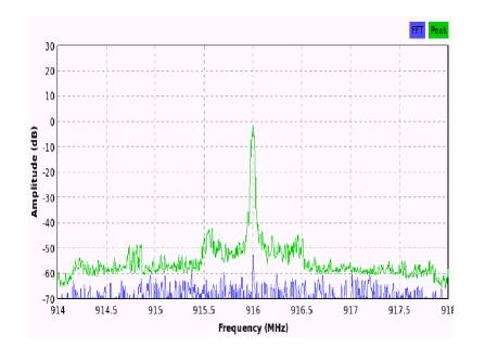
The results shown in Fig. 6 depict the power spectrum of the transmitted signal from the GNURadio transmitter. They correspond to the output of the FFT spectrum-analyser tool that is included in the GNURadio framework. A peak is visible with our software transceiver when we choosing the channel at 916 MHz, with a number of samples per symbol which allow us to have an intermediate frequency of MHz. This value is in concordance with the values taken by the transmitted power spectral density of the IEEE 802.15.4 standard (see Fig. 6). Furthermore, frequencies at the edge of the main band are visible but strongly attenuated. These imperfections may be due to the roll-off characteristics of the interpolation filter in the up-conversion processing of the FPGA.
 |
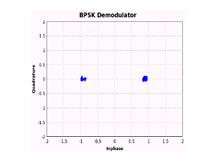 |
We use a D-BPSK modulation and the receiver constellation is depicted in Fig. 7.
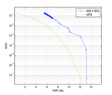
The performance of D-BPSK modulation is evaluated without packet generation. The flexibility of the GNU radio permits the reconfigurability of the transmitter/receiver chain by adding or replacing blocks. In a first experiment, we use the modulator and demodulator chains to measure the BER and SNR parameters. Fig. 8 illustrates the average BER versus the input SNR (dB) for the frequency MHz and for the MFB Matched Filter Bound of D-BPSK modulation. The results have been computed by changing the amplifier amplitude values from 1000 to 12000 with the step of 100 for a time period of seconds. Although noisy, the results are in concordance to the theory, proving that the implementation is working.
 |
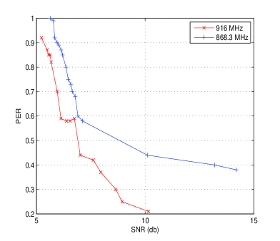
In the second experiment, the packet generator and packet sink are connected to the transmission chain and we measure a PER parameter as a function of SNR (dB). The measures are obtained by sending for each amplifier amplitude 100 packets apart from 0.2 s between two successive packets. The PER decreases when the amplifier amplitude increases. The shape of the curve is compliant to that of the BER (show Fig.9). The PER depends on the synchronization between the transmitter and the receiver. We noticed that the synchronization does not occur at every execution. This issue may arise when the USRP does not clear its buffer memory.
V Conclusion
In this paper, we report the implementation of the IEEE 802.15.4 standard on a SDR transceiver for the 915/868 MHz band. The SW stack is based on the GNURadio open-source project and the HW is based on an USRP1 platform from Ettus Research. The BER and PER of the 802.15.4 have been calculated independently in an indoor environment by changing the signal amplitude. The results are coherent with the lower theoretical bound that is expected. The obtained performances of the PER are degraded compared to the BER because the successful receiving packets depend on the synchronization and the BER.
References
- [1] J. Sabater, J. M. Gomez, and M. Lopez, “Towards an IEEE 802.15.4 SDR transceiver,” in Icecs. Ieee, 2010, pp. 323–326.
- [2] N.-J. Oh, S.-G. Lee, and J. Ko, “A CMOS 868/915 MHz direct conversion. ZigBee single-chip radio,” IEEE Communications Magazine, vol. 43, no. 12, pp. 100–109, 2006.
- [3] T. Ulversoy, “Software Defined Radio: Challenges and Opportunities,” IEEE Communications Surveys and Tutorials, vol. 12, no. 4, pp. 531–550, 2010.
- [4] E. Blossom, “GNU radio: tools for exploring the radio frequency spectrum,” Linux J., vol. 2004, no. 122, pp. 4—-, Jun. 2004.
- [5] Ettus, “About Ettus Research,” Feb. 2011. [Online]. Available: https://www.ettus.com/product
- [6] M. N. O. Sadiku and C. M. Akujuobi, “Software-defined radio: a brief overview,” Ieee Potentials, vol. 23, no. 4, pp. 14–15, 2004.
- [7] Gnuradio.org, “Gnu Radio,” Feb. 2011. [Online]. Available: http://gnuradio.org/redmine/projects/gnuradio/wiki
- [8] Ossie.wireless.vt.edu, “SCA-Based Open Soruce Software Defined Radio,” Feb. 2011. [Online]. Available: http://ossie.wireless.vt.edu/
- [9] “IEEE Standard for Local and metropolitan area networks–Part 15.4: Low-Rate Wireless Personal Area Networks (LR-WPANs),” pp. 1–314, 2011.
- [10] T. Schmid, “GNU Radio 802.15.4 En- and Decoding,” Tech. Rep., 2006.
- [11] G. R. Danesfahani and T. G. Jeans, “Optimisation of modified Mueller and Muller algorithm,” Electronics Letters, vol. 31, no. 13, pp. 1032–1033, Jun. 1995.