First-Principles Calculation of Thermal Transport in the Metal/Graphene System
Abstract
Thermal properties in the metal/graphene (Gr) systems are analyzed by using an atomistic phonon transport model based on Landauer formalism and first-principles calculations. The specific structures under investigation include chemisorbed Ni(111)/Gr, physisorbed Cu(111)/Gr and Au(111)/Gr, as well as Pd(111)/Gr with intermediate characteristics. Calculated results illustrate a strong dependence of thermal transfer on the details of interfacial microstructures. In particular, it is shown that the chemisorbed case provides a generally smaller interfacial thermal resistance than the physisorbed due to the stronger bonding. However, our calculation also indicates that the weakly chemisorbed interface of Pd/Gr may be an exception, with the largest thermal resistance among the considered. Further examination of the electrostatic potential and interatomic force constants reveal that the mixed bonding force between the Pd and C atoms results in incomplete hybridization of Pd and graphene orbital states at the junction, leading effectively to two phonon interfaces and a larger than expected thermal resistance. Comparison with available experimental data shows good agreement. The result clearly suggests the feasibility of phonon engineering for thermal property optimization at the interface.
pacs:
63.22.-m,65.80.-g,73.40.Ns,66.70.-fI Introduction
As the critical dimensions of modern electronic devices approach the nanoscale, the power density of integrated circuits has soared drastically, forcing the issue of thermal management to the forefront. Faced with the challenge, graphene has recently emerged as one of the key candidates for the next-generation low-power electronics for its superb properties. Fundamental understanding of thermal transport in the graphene based structures is crucial from the perspective of both low-dimensional physics and practical applications of this emerging material system. Particularly, the metal contact with graphene is of interest as it provides not only an essential part of any active device but also a primary path of heat dissipation. Thermal conduction across the heterogeneous metal/graphene (Gr) interface is characterized by the interfacial resistance often known as the Kapitza resistance. Pollack1969 The heat current is mainly carried by phonons, while the electronic contribution is considerably smaller. It was found recently that thermal energy transfer via direct electron-phonon coupling astride the heterointerface is insignificant (compared to the phonon-phonon interactions) in metal/dielectric structures including those employing graphene. Lyeo2006 ; Hopkins2012
As in the case of most layered structures, the properties of the metal/graphene system are also expected to depend heavily on the bonding chemistry and detailed structures at the interface. It was recently demonstrated that the bonding between graphene and metal atoms can be divided into two categorieschemisorption and physisorption. Khomyakov2009 While chemisorption opens a band gap in graphene due to hybridization between the graphene - and metal -orbitals, the Dirac-cone feature of graphene is preserved at the physisorbed interfaces. Subsequent investigations illustrated that physisorption is observed for Ag, Al, Cu, Cd, Ir, Pt, and Au, whereas the Ni, Co, Ru, Pd, and Ti interfaces belong to chemisorption. Ran2009 ; Gong2010 ; Gong2012 However, their impact on phonon/thermal transport has received much less attention with only a limited number of studies available in the literature. A molecular dynamics calculation was conducted for heat transfer between allotropic carbon nanotubes and Cu substrate. Gao2011 On the side of experiment, measurement of thermal conductance was reported for the Cu/Gr, Al/Gr, Ti/Gr and Au/Gr cases with the obtained values ranging Km2/W. Schmidt2010
In this paper, we attempt to provide a detailed theoretical account of interfacial thermal resistance in the metal/graphene system. The sample structures are chosen to reflect the range of typical interfaces from chemisoprtion to physisorption for a comprehensive analysis. Since atomistic details of phonon dynamics are crucial for the accurate outcome, the adopted theoretical approach utilizes a first-principles analysis based on density functional theory (DFT) to calculate the interatomic force constant (IFC) matrix. Baroni2001 ; Gonze1997 ; Alam2011 Then the desired phonon transmission function and the thermal current are determined via Green’s function techniques Lee1981 ; Datta1997 ; Nardelli1999 ; Allen1993 and the Landauer formalism. Landauer1970 The obtained results are compared with experimental and other theoretical data available in the literature.
The rest of the paper is organized as follows. First, the structures of metal/graphene systems under investigation are discussed briefly with the focus on the interfacial bonding environment. Then, a summary description of the adopted thermal transport model is provided including the details of numerical implementation. Finally, discussion/analysis of the calculated interfacial phonon transmission and Kapitza resistance is presented.
II Metal/graphene interfaces
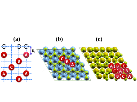
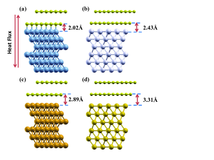
The heterogeneous system of interest is graphene on the (111) surface of a metal (Ni, Pd, Cu, and Au). If the lattice constant of graphene is fixed at the optimized value 2.46 Å, less than 5% lattice mismatch is introduced when these metals of face-centered cubic symmetry are made commensurate with the graphene lattice. A 11 unit cell is formed for Ni/Gr and Cu/Gr, while a 22 construction is necessary for Pd/Gr and Au/Gr to accommodate larger sizes of metal atoms. The top view and stacking orders of the four different material combinations are shown schematically in Fig. 1, representing the ideal atomic arrangement at the metal/graphene contacts. While useful in illustrating the geometric construction, these arrangements are insufficient to account for details of the interfacial microstructures. Instead, the realistic structures can be obtained through geometry optimization using first-principles calculation (see, for example, Fig. 2). As indicated earlier, the relaxed metal/graphene interfaces are generally divided into two categories, chemisorption and physisorption, depending on the bonding energies, interfacial separations, and orbital hybridizations. In accord with earlier studies, Gong2010 our calculation clearly illustrates that Ni and graphene bond strongly at the interface through hybridization between Ni -orbitals and C -orbitals. Strong coupling also results in a relatively small interfacial separation (2.02 Å). On the other hand, Cu and Au are physisorbed on graphene and form a weak van der Waals bonding with a larger interlayer distance (2.89 Å and 3.31 Å, respectively). comm2 For the Pd(111)/Gr structure, it is observed that the interaction between Pd and C atoms may be smaller than the strong chemical bonding, leading effectively to the mixed character at the interface (i.e., of both chemisorption and physisorption). Ran2009 This unique combination may set the Pd/Gr system apart from the other metal/graphene interfaces as elaborated further in Sec. IV.
III Theoretical Model
III.1 Thermal transport in the atomistic Green’s function formulism
Phonon transport is originated from the dynamics of the lattice or lattice vibrations. Ashcroft1976 Since the investigation concerns the interfacial properties, transport in the immediate region astride the interface can be treated ballistic and a quantum mechanical treatment in the Landauer framework Landauer1970 is adequate to capture the essential features. Accordingly, we consider a three parted system where the central interface region (i.e., the region of interest) is connected to the thermal reservoirs on the left and the right with two semi-infinite leads (labeled L and R), often known as the lead-conductor-lead configuration. Nardelli1999 ; Zhang2007 Accounting for only the phonon contribution, the thermal current density is then given as:
| (1) |
where is the equilibrium phonon distribution in the left or right thermal reservoir (at temperature ) and denotes the phonon transmission function. In this expression, is directly related to the lattice dynamics of the given structure containing all of the relevant details. Its computation can be achieved in a manner analogous to that of electron transmission coefficients across nanoscale heterostructures by using such approaches as the atomistic Green’s function method. Nardelli1999 ; Zhang2007 ; Calzolari
The first step of calculating the thermal current [i.e., ] is to obtain the IFCs defined as:
| (2) |
where is the total energy of the system, R is a Bravais lattice vector, and is the displacement of the atom (of the unit cell) in the direction with respect to the equilibrium position. The cases can be determined in terms of those in Eq. (2) via the acoustic sum rule. Ashcroft1976 The IFCs in turn define the harmonic matrix
| (3) |
and the dynamical matrix
| (4) |
where is the mass of the atom. In the considered lead-conductor-lead system, this harmonic matrix can be written formally as Zhang2007 ; Calzolari
| (5) |
and, finally, the dynamical equation as
| (6) |
Here, is the matrix in each of the three regions ( L,C,R), while represents the phonon coupling at the interfaces between the central region and the two leads ( L,R). This expression in Eq. (6) is clearly analogous to the governing equation of the electronic system, with and [see, for example, Eq. (1) of Ref. Nardelli1999, ]. Accordingly, calculation of phonon transmission can directly follow the Green function techniques developed initially for electronic transport as mentioned earlier.
Utilizing the identified parallelism, the phonon transmission function is written straightforwardly as:
| (7) |
where are the retarded (r) and advanced (a) Green’s functions of the central region and correspond to the coupling with the left and right leads, respectively. Further, the Green’s function and the coupling functions can be obtained from Calzolari
| (8) |
| (9) |
where the self-energy terms
| (10) |
are evaluated with the help of the Green’s function in the corresponding leads ( L,R). The transfer matrix method offers a very efficient approach to calculate in the semi-infinite lead by treating it as a stack of principal layers with only nearest-layer interactions. Lee1981 ; Sancho1985 ; Nardelli1999 The advanced terms (with superscript ) are given as Hermitian conjugates. Additional details of underlying theoretical formulation can be found in Ref. Calzolari, .
Once the phonon transmission function is obtained, thermal and thermoelectric properties can be evaluated. A particularly relevant quantity is the thermal resistance of the system that is given as the inverse of the thermal conductance:
| (11) |
While the model described above is for the case of two leads (or reservoirs), extension to a multi-terminal system is trivial as it has been demonstrated in electronic transport. Jayasekera2007
III.2 Numerical implementation
The calculations are performed in the DFT framework, as it is implemented in the QUANTUM-ESPRESSO package, Giannozzi2009 with ultrasoft pseudopotentials in the local density approximation. comment A minimum of 35 Ry is used for the energy cut-off in the plane wave expansion along with the charge truncation of 350 Ry. In addition, the Methfessel-Paxton first-order spreading is employed with the smearing width of 0.01 eV. The momentum space is sampled on a Monkhorst-Pack mesh in the first Brillouin zone. In the construction of interfacial structure, two layers of graphene and three to five layers of metal (depending on the material) are considered in the calculation. The unit cell is set to the lattice constant of graphene and the geometry optimization is performed to find the energy minimum structure. The Hellman-Feynman force is taken into account in each iterative solution. Figure 2 shows the resulting interface structures of the considered material combinations. They serve as the central region in the previously mentioned lead-conductor-lead configuration. Two leads consisting of respective bulk materials (i.e., bulk metal and graphene/graphite) connect seamlessly to the interface region and are modeled separately. No appreciable mismatch (i.e., resistance) exists between the leads and the conductor. Simulation results show that the k-space grids of 662 and 666 are sufficient for the interface region and the bulk leads, respectively, with good convergence in the relevant characteristics.
With the optimized realistic interface structures, the next step is to evaluate vibrational properties including IFCs. While analytical force constant models have been used widely in such materials as carbon or silicon based systems, Al-Jishi1982 ; Saito1998 ; ZhangMingo2007 they are not directly applicable in the current investigation due to the lack of information on the required bonding details between carbon and metal atoms. Instead, we calculate lattice dynamics, also within the DFT formalism for accuracy, by utilizing a perturbative treatment known as density functional perturbation theory (DFPT). Baroni2001 The IFCs are then obtained by Fourier analyzing the set of dynamical matrices generated from the first-principles calculation under the harmonic approximation [see Eq. (4)]. With the IFCs of bulk leads, we can build , ( L,R) that enter Eq. (5); While the on-site matrix and coupling matrices and can be constructed from the IFCs of the central part. Then the phonon transmission can be evaluated using Eq. (7) with the Green’s function calculated from the transfer matrix technique. Finally, the thermal resistance of the structure and the Kapitza resistance at the metal/graphene junction can be evaluated by Eq. (11). Since this quantity of interest is defined in the near-equilibrium condition (i.e., an infinitesimally small temperature gradient across the structure; see Eq. (11)], an equilibrium treatment is adequate with no need for an iterative solution.
IV Results and Discussion
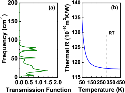
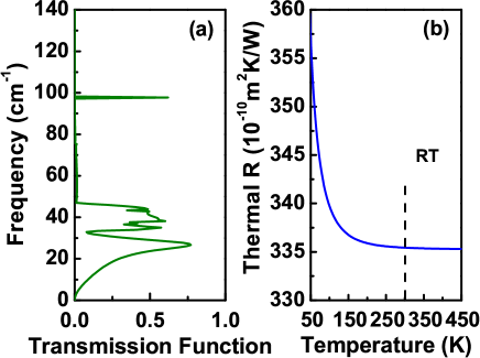
Of the material combinations under investigation, graphene on the Cu (111) surface is examined first due, partly, to its widespread use. As indicated by the obtained phonon transmission function in Fig. 3(a), only the low lying acoustic branches (below 100 cm-1) play the dominant role in phonon transport at the interface. The impact of optical branches is orders of magnitude smaller. The resulting thermal resistance is plotted in Fig. 3(b). Since the total resistance of the structure [i.e., Eq. (11)] contains the contribution from the leads as well, the intrinsic thermal resistance at the junction is deduced by subtracting this portion in a manner analogous to electrical transport. Datta1997 ; Laikhtman1994 At T=300 K, the estimated interfacial thermal resistance of the Cu/Gr structure is Km2/W. The interfacial resistance exhibits the 1/T dependence in the low temperature region (50150 K), while staying almost invariant between 150 K and 450 K.
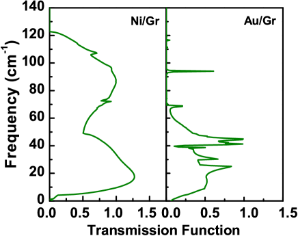
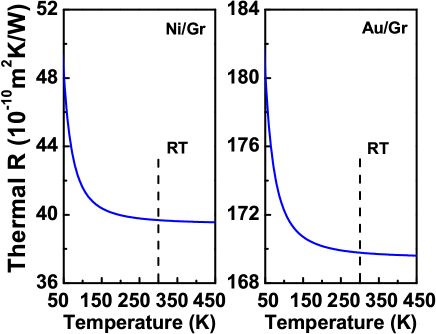
When the calculation is extended to chemisorbed Ni and physisorbed Au, the respective results appear to be similar in many aspects. However, one interesting point to note is that the Ni/Gr interface shows the phonon transmission coefficient whose frequency dependence is much broader with fewer resonant features (see Fig. 4). This is substantially different from those of the physisorbed metal/graphene interfaces (both Au and Cu). The mixed nature of phonon dynamics at the chemisorbed interface (thus, a smaller mismatch) is thought to be the main origin of enhanced phonon transmission and eventually a smaller interfacial resistance. The estimated value for Ni/Gr is about Km2/W at 300K, whereas it is more than four times larger for Au/Gr ( Km2/W) as indicated in Fig. 5. The obtained result for physisorbed Au/Gr shows good agreement with the measurement data available in the literature ( Km2/W). Schmidt2010 ; Hopkins2012 In contrast, the conventional diffuse mismatch model shows large discrepancies. Even with the added sophistication such as anisotropy in graphitic materials and multiple heat transfer mechanisms, it substantially overestimates the thermal resistance for Au/Gr ( Km2/W). Duda2010 A similar calculation yields Km2/W at the Cu/Gr interface. Chang2012
Comparison between different graphene/metal systems thus far clearly indicates that the chemisorbed interface is generally more favorable than the physisorbed in term of thermal transport. The presence of strong bonding and the smaller interlayer separation (e.g., 2.02 Å of Ni/Gr vs. 3.31 Å of Au/Gr) all support this conclusion that is also in accord with a recent experimental study. Schmidt2010 One potential exception may be graphene on the Pd (111) surface. Since their bonding characteristics supposedly show both chemisorbed and physisorbed nature as mentioned earlier, it is reasonable to anticipate that the interfacial thermal resistance would fall in between as well. However, the calculation suggests that Pd may not follow the trend and actually have the largest resistance of those considered (a value of Km2/W at room temperature; see Fig. 6). Most notably, phonon transmission is greatly suppressed between approx. 40 cm-1 and 100 cm-1 even when compared to Cu/Gr and Au/Gr. This result is counterintuitive, particularly when the interlayer distance (which tends to indicate the interaction strength) behaves as expected; namely, between the values of chemisorbed and physisorbed structures as indicated in Fig. 2.
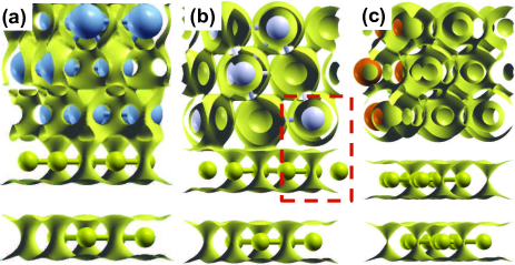
The identified peculiarity is examined further by analyzing detailed microstructures of the corresponding metal/graphene interfaces. The electrostatic potential isosurface plotted in Fig. 7 clearly illustrates that strong hybridization between the and orbitals at the chemisorbed Ni/Gr interface ”glues” Ni and graphene together, making them essentially one unit. As such, propagating phonons transmit through the Ni/Gr interface with relative ease. On the other hand, the weak interaction between Au and C atoms in the Au/Gr system forms a barrier at the interface, which strongly scatters phonon transmission. For Pd/Gr, it is revealed that the mixed bonding force between Pd and C atoms is indeed smaller than the strong chemical bonding (namely, chemisorption) as evident from the partly detached bond in the boxed region. However, the interaction still alters the orbital states of first layer graphene, making them sufficiently distinct from those of second layer graphene. Consequently, phonons potentially face two interfaces for transmission instead of one. A force constant analysis between atomic layers can clarify the latter point with numerical certainty.
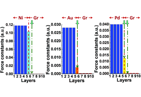
Figure 8 illustrates the interlayer force constants deduced from the DFPT calculation. The height of each bar symbolizes the interaction strength between two neighboring layers. For example, the first bar on the left denotes the interaction between layers 1 and 2; the next bars are for layers 2 and 3, and so on. In all three plots, the metallic layers are up to layer 5 and graphene starts from layer 6; accordingly, the physical interface of two heterogeneous materials is located between layers 5 and 6. On the other hand, the real interface or barrier which impedes phonon transport is characterized by the abrupt change of force constant. In Ni/Gr, it is illustrating to note that the force constant between the Ni and graphene layers right at the interface (the bar between layers 5 and 6) shows only a slight difference with those between Ni layers on the left (i.e., 0.103 a.u. vs. 0.118 a.u., where a.u. stands for atomic Rydberg units). Instead, transmitting phonons experience the major barrier at the interface between layers 6 and 7, where the force constant changes the most drastically. Due to strong hybridization discussed earlier, the first layer of graphene is absorbed by Ni atoms, leaving it practically decoupled from the second graphene layer. Nevertheless this is a Gr/Gr interface and it is reasonable to expect a relatively smaller resistance. comm3 For physisorbed Au, the characteristics are as expected. Namely, we get a clear separation of gold bonding and graphene bonding at the interface between layers 5 and 6 (0.028 a.u. vs. 0.004 a.u.). Since gold atoms are much heavier than carbon, acoustic phonon frequencies experience a large mismatch hence, a large thermal resistance. When it comes to Pd/Gr, the incomplete mixing of the first graphene layer indeed results in two-step changes in the force constant between layers 5 and 6 as well as between 6 and 7 (i.e., from 0.04 a.u. to 0.0125 a.u. then to a.u.), leading effectively to two phonon interfaces as mentioned earlier, and a larger than expected interfacial thermal resistance. One cautionary point is that the calculation outcome could experience modifications if the graphene film is just one monolayer thick. Then, the thermal resistance values can be substantially smaller than the presented, particularly when significant mixing is involved. Our current theoretical formalism is not equipped to address isolated systems, for which the ideal leads are difficult to construct.
Additional insight into interfacial phonon transport may be gained by comparing the results of metal/graphene structures with those involving dielectric substrates. As summarized in Table 1, Mao2012 ; Chen2009 a couple of likenesses can be readily noted. That is, the calculated interfacial thermal resistance of Ni/Gr is close to the corresponding value of BN/Gr ( vs. Km2/W), while Pd/Gr and SiC/Gr are very much alike ( vs. Km2/W). Since it is the Gr/Gr interface in Ni/Gr that determines the thermal resistance, the chemisorbed case can be understood roughly analogous to the epitaxial Gr/BN structure, also consisting of two materials of similar two-dimensional (2D) crystal type. In the case of Pd/Gr vs. SiC/Gr, both harbor effectively more than one interface/barrier for phonon transmission. As it is well known, the studied structure of epitaxial graphene grown on the SiC (0001) surface contains an additional carbon buffer layer at the interface that does not have the characteristic sp2 bonding. Hence, the observed large interfacial thermal resistance in SiC/Gr is consistent with the discussion on Pd/Gr given earlier (i.e., two phonon barriers in series). Finally, the physisorbed structures with a weak van der Waals bonding between two dissimilar materials (e.g., 3D metal vs. 2D graphene) may correspond to exfoliated graphene placed on a non-2D crystal substrate such as SiO2. While comparable theoretical estimate based on a first principles calculation is not available for SiO2/Gr, the recent experimental data Chen2009 of Km2/W show good match with the values of Cu/Gr and Au/Gr obtained in the current investigation. These analyses highlight how significantly the atomic bonding details can influence the interfacial thermal properties, leading potentially to phonon engineering for active heat management. Hopkins2012 ; Mao2012 It also illustrates the inadequacy of various theoretical treatments including the molecular dynamics approach Chang2012 that cannot properly account for the required level of physics a priori.
V Summary
Thermal transport in the metal/graphene heterostructures is investigated by using a first principles method and the Green’s function approach within the Landauer formalism. The obtained interfacial thermal resistances are Km2/W, Km2/W, and Km2/W at room temperature for the Ni/Gr, Cu/Gr and Au/Gr structures, respectively, indicating generally more effective thermal transfer at the chemisorbed surface owing to the smaller interlayer separation and stronger bonding with graphene. However, calculations also illustrate that a weakly chemisorbed case such as Pd/Gr could actually lead to an interface even more resistive than that encountered at the physisorbed surface. Detailed examination of electrostatic potential and force constants identifies the formation of an intermediate layer (a consequence of incomplete mixing) and the resulting multiple phonon interfaces/barriers as the potential origin of the observed deviation. Comparison with the corresponding calculations in the graphene/substrate systems reveals strong correlation between seeming differences in material combination, further emphasizing the role of atomic-level ab initio analysis. The obtained theoretical results show good agreement with experimental data available in the literature.
Acknowledgements.
This work was supported, in part, by SRC/NRI SWAN and NSF NERC ASSIST (EEC-1160483).References
- (1) G. L. Pollack, Rev. Mod. Phys. 41, 48 (1969).
- (2) H.-K. Lyeo and D. G. Cahill, Phys. Rev. B 73, 144301 (2006).
- (3) P. E. Hopkins, M. Baraket, E. V. Barnat, T. E. Beechem, S. P. Kearney, J. C. Duda, J. T. Robinson, and S. G. Walton, Nano Lett. 12, 590 (2012).
- (4) P. A. Khomyakov, G. Giovannetti, P. C. Rusu, G. Brocks, J. van den Brink, and P. J. Kelly, Phys. Rev. B 79, 195425 (2009).
- (5) Q. Ran, M. Gao, X. Guan, Y. Wang, and Z. Yu, Appl. Phys. Lett. 94, 103511 (2009).
- (6) C. Gong, G. Lee, B. Shan, E. M. Vogel, R. M. Wallace, and K. Cho, J. Appl. Phys. 108, 123711 (2010).
- (7) C. Gong, D. Hinojos, W. Wang, N. Nijem, B. Shan, R. M. Wallace, K. Cho, and Y. J. Chabal, ACS Nano 6, 5381 (2012).
- (8) F. Gao, J. Qu, and M. Yao, J. Appl. Phys. 110, 124314 (2011).
- (9) A. J. Schmidt, K. C. Collins, A. J. Minnich, and G. Chen, J. Appl. Phys. 107, 104907 (2010).
- (10) S. Baroni, S. de Gironcoli, A. Dal Corso, and P. Giannozzi, Rev. Mod. Phys. 73, 515 (2001).
- (11) X. Gonze and C. Lee, Phys. Rev. B 55, 10355 (1997).
- (12) A. Alam, R. K. Chouhan, and A. Mookerjee, Phys. Rev. B 84, 224309 (2011).
- (13) D. H. Lee and J. D. Joannopoulos, Phys. Rev. B 23, 4988 (1981); ibid. 23, 4997 (1981).
- (14) S. Datta, Electronic Transport in Mesoscopic Systems (Cambridge University Press, Cambridge, 1997).
- (15) M. Buongiorno Nardelli, Phys. Rev. B 60, 7828 (1999).
- (16) P. B. Allen and J. L. Feldman, Phys. Rev. B 48, 12581 (1993).
- (17) R. Landauer, Phil. Mag. 21, 863 (1970).
- (18) Van der Waals interactions are partly included in our calculation. Specifically, the molecular interaction originated from the static dipole formation is intrinsically considered. On the other hand, dynamic phenomena such as the instantaneous dipole formation are currently beyond the scope of the DFT formalism.
- (19) N. W. Ashcroft and N. D. Mermin, Solid State Physics (Holt, Rinehart and Winston, New York, 1976).
- (20) W. Zhang, T. S. Fisher, and N. Mingo, Numer. Heat Transfer, Part B 51, 333 (2007).
- (21) A. Calzolari, T. Jayasekera, K. W. Kim, and M. Buongiorno Nardelli, J. Phys.: Condens. Matter 24, 492204 (2012).
- (22) M. P. Lopez Sancho, J. M. Lopez Sancho, J. M. L. Sancho, and J. Rubio, J. Phys. F: Met. Phys. 15, 851 (1985).
- (23) T. Jayasekera and J. W. Mintmire, Nanotechnol. 18, 424033 (2007).
- (24) P. Giannozzi, S. Baroni, N. Bonini, M. Calandra, R. Car, C. Cavazzoni, D. Ceresoli, G. L Chiarotti, M. Cococcioni, I. Dabo, A. Dal Corso, S. de Gironcoli, S. Fabris, G. Fratesi, R. Gebauer, U. Gerstmann, C. Gougoussis, A. Kokalj, M. Lazzeri, L. Martin-Samos, N. Marzari, F. Mauri, R. Mazzarello, S. Paolini, A. Pasquarello, L. Paulatto, C. Sbraccia, S. Scandolo, G. Sclauzero, A. P. Seitsonen, A. Smogunov, P. Umari, and R. M. Wentzcovitch, J. Phys. Condens. Matter 21, 395502 (2009).
- (25) While the relativistic pseudopotentials were also considered for the potential impact of spin-orbit coupling in the case of Au/Gr, the calculation results indicate generally negligible differences. Accordingly, this effect (i.e., spin-orbit coupling) is ignored in the rest of the study.
- (26) R. Al-Jishi and G. Dresselhaus, Phys. Rev. B 26, 4514 (1982).
- (27) R. Saito, G. Dresselhaus, and M. S. Dresselhaus, Physical Properties of Carbon Nanotubes (Imperial College Press, London, 1998).
- (28) W. Zhang, N. Mingo, and T. S. Fisher, Phys. Rev. B 76, 195429 (2007).
- (29) B. Laikhtman and S. Luryi, Phys. Rev. B 49, 17177 (1994).
- (30) J. C. Duda, P. E. Hopkins, T. E. Beechem, J. L. Smoyer, and P. M. Norris, Superlatt. Microstruct. 47, 550 (2010).
- (31) S.-W. Chang, A. K. Nair, and M. J. Buehler, J. Phys. Condens. Matter 24, 245301 (2012).
- (32) In the current treatment, the thermal resistance at an ideal Gr/Gr interface is zero. In reality, it is finite, of the order of Km2/W [see, for example, Z. Wei, Z. Ni, K. Bi, M. Chen, and Y. Chen, Phys. Lett. A 375, 1195 (2011)]. In any case, the value is much smaller than those at the metal/graphene boundaries despite the comparable interlayer separation.
- (33) R. Mao, B. D. Kong, K. W. Kim, T. Jayasekera, A. Calzolari, and M. Buongiorno Nardelli, Appl. Phys. Lett. 101, 113111 (2012).
- (34) Z. Chen, W. Jang, W. Bao, C. N. Lau, and C. Dames, Appl. Phys. Lett. 95, 161910 (2009).
| Interface | Interfacial | Thermal resistance | |
| environment | separation | ( Km2/W) | |
| Ni/Gr | Chemisorption | 2.02 Å | 39 |
| Cu/Gr | Physisorption | 2.89 Å | 118 |
| Au/Gr | Physisorption | 3.31 Å | 170 |
| Pd/Gr | Mixed | 2.43 Å | 335 |
| BN/Gra | Flat | 3.43 Å | 54 |
| SiC/Gra | Rough (buffer layer) | 3.89 Å | 361 |
| SiO2/Grb | Rough | 4.2 Å | 56120 |
| aRef. Mao2012, | |||
| bRef. Chen2009, |