A Double Ion Trap for Large Coulomb Crystals
Abstract
While the linear radiofrequency trap finds various applications in high-precision spectroscopy and quantum information, its higher-order cousin, the linear multipole trap, is almost exclusively employed in physical chemistry. Recently, first experiments have shown interesting features by laser-cooling multipole-trapped ion clouds. Multipole traps show a flatter potential in their centre and therefore a modified density distribution compared to quadrupole traps. Micromotion is an important issue and will certainly influence the dynamics of crystallized ion structures. Our experiment tends to investigate possible crystallization processes in the multipole. In a more general way, we are interested in the study of the dynamics and thermodynamics of large ion clouds in traps of different geometry.
Keywords:
multipole trap, laser cooling:
37.10.Ty; 52.25.Kn;52.27.Jt1 Multipole traps
Thirty years after Wolfgang Paul’s introduction of the 3D radiofrequency (rf) ion cage, the linear version of the quadrupole trap has been proposed for use in high precision spectroscopy Prestage et al. (1989). Further evolution to linear traps with an increased number of electrodes has been motivated by the profile of the local rf electric field which is no more linear with the distance to the trap axis but is ruled by a higher-order law. As a consequence, for the same potential depth as in a quadrupole trap, multipole rf traps offer a central trapping volume nearly free of rf electric field and therefore exempt of rf driven motion. This is of major importance in physical chemistry Gerlich (1992), where the kinetic energy of the collision must be controlled and ideally kept very low for cold collisional reaction studies. The cryogenic 22-pole trap is widely used to study ion-molecule reactions and complex molecular spectroscopy, a recent review of this trap and its applications can be found in Wester (2009).
For this type of trap, only one application in frequency metrology is reported which takes advantage of the nearly field free zone offered by linear multipole traps to reduce the rf induced Doppler effect Prestage and Weaver (2007). In this device, the multipole trap is combined in line with a quadrupole trap, using a shuttling protocol between both parts in order to combine the advantages of both confinement zones. Recently, first experimental results have been reported on laser-cooling in an octupole and in a hexapole trap Okada et al. (2007, 2009), limited however by experimental constraints. Numerical simulations Okada et al. (2007) have demonstrated that laser-cooled ions form stable structures, called Coulomb crystals, in these traps. Due to the increase of the particle density with the distance from the axis expected for cold samples in multipole traps Champenois (2009), Coulomb crystals show a hollow core structure Okada et al. (2009), very different from what is observed in quadrupole rf traps where the ion density of cold sample is uniform Hornekær and Drewsen (2002). The stability of hollow core Coulomb crystal structures remains to be studied, under the competing influences of rf driven motion (micromotion) and laser-cooling.
We have designed and realized an experimental device which is dedicated to the study of stable ion structures when trapped in a multipole geometry. In the following we start by giving a brief introduction to the theory that rules the dynamics of ions stored in a linear multipole trap. We then present some of the studies that have been carried out numerically in these systems. The experimental device and first results are described in the last part of this paper.
2 Theory of the multipole trap
We assume a linear multipole trap made of rods where a radio-frequency voltage of peak-to-peak amplitude and frequency is applied to the rods of the trap, with exact phase opposition between adjacent rods. The potential along the -axis is created by applying a DC-voltage onto the end-cap electrodes. For reasons of simplicity, we assume that no DC-voltages are applied on the rf rods. The total effective time-averaged potential (or pseudopotential) in this device is then
| (1) |
where is a characteristic energy, is a loss factor depending on the geometry of the end electrodes relative to the rods. includes all screening and geometric effects that explain the difference between the potential applied onto the end electrodes and the effective potential seen by the ions Champenois (2009). is smaller than 0.02 in our experiment. For , the two contributions to the radial effective potential are quadratic and no major impact is expected from the deconfining effect of the axial confinement on the radial trapping. On the contrary, for , the addition of a -contribution to the rf-pseudopotential modifies its shape. The axis of the trap becomes an unstable position and the potential minimum is shifted to defined by
| (2) |
Taking into account this shift of potential minimum is relevant when few cold ions are trapped, as they fill the bottom of the potential well. When large samples are considered, and following Dubin and O’Neil concerning the thermal equilibrium states of trapped non-neutral plasmas Dubin and O’Neil (1999), one can show that the density distributions are completely controlled by the rf induced effective potential with no contribution from the DC-voltage Champenois (2009):
| (3) |
This distribution is uniform only for the quadrupole geometry. As mentioned above, for higher order geometries, the density is expected to increase with the distance from the center of the trap, leading to a tube-like self-organized structure. This prediction in the mean-field approach is confirmed by molecular dynamics simulations for ion numbers above a few hundred Calvo et al. (2009).
A detailed discussion of the dynamics and thermodynamics of an ion cloud in a multipole trap can be found in Champenois (2009).
3 Numerical simulations with few ions
The equations of motion of an ion in a multipole trap of order higher than are non-linear and coupled in the two radial directions and . Therefore, there are no known analytical solutions and the stability of a trajectory depends on initial conditions as well as trapping parameters. Numerical simulations are then useful tools to get insight into ion dynamics and to identify the relevant trapping parameters for each set-up.
We have developed a simulation code which follows the actual trajectories of the trapped ions during a large number of rf periods Marciante et al. (2010). This code takes into account all forces that act on the trapped particles including laser-cooling. The simulation can be run with the time-averaged effective potential approach or making use of the local rf electric field. The comparison of these two approaches allows us to study the influence of rf driven motion on the ion dynamics. Following exactly a large number of ions in the long run is of course limited by computer performances. At present, all simulations are carried out with less than 1000 ions, higher numbers can be achieved by parallelizing the simulation code which is work in progress.
The described code has been used to lead investigations a priori to the experiments. We have shown that for a small number of trapped ions (roughly below 100) and a steep but realistic trapping potential, the trapped particles settle in the potential well in to form ring structures (see Eq.2 and Fig.1) and the number of rings can be controlled by the potential in -direction Marciante et al. (2012). We first considered this ring structure for frequency metrology applications Champenois et al. (2010) but recent work suggests that it can also be the realization of a space-time crystal Li et al. (2012).

In comparison with the string configuration formed by few ions in a linear quadrupole trap, located along the zero node line of the trapping field, this ring structure suffers from rf driven motion at the ion equilibrium point. This motion can not be laser cooled and can induce ion-ion collision heating (rf heating). The advantage of keeping the ions in a single plane is to decouple the axial degree of motion from the radial one Marciante et al. (2010); Champenois et al. (2010). The Doppler cooling limit can then be reached along the axial direction despite the radial rf driven motion. Actually, in contrast to an ion string in a linear quadrupole trap, all ions in a ring will experience identical conditions. Rings of ions and a radius of about 400 m could allow the realization of an atomic frequency standard reaching a frequency uncertainty which is comparable to its single-ion counterpart Champenois et al. (2010), but with a times higher signal-to-noise ratio. This would assure higher short-term frequency stability and can eventually relax constraints on the stabilization of the clock laser due to shorter probing durations.
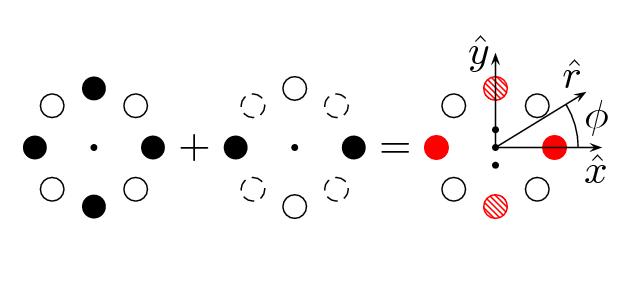
Another possibility to avoid the rf-driven motion is the combination of rf electric fields of different geometries in a single device, creating extra field-free regions where ions can be trapped without experiencing micromotion Marciante et al. (2011). The general concept is the superimposition of a lower-order multipole potential onto the existing -pole. A small additional DC voltage will balance ion positions. Figure 2 illustrates the example of a weak quadrupole potential added to an octupole trapping field. Two additional lines of field-free region are created in this case.

4 Experimental set-up
4.1 Design
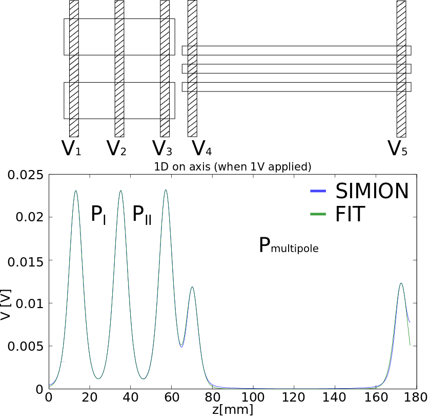
The simulations of the small structures described in the previous section demonstrate the underlying processes in the multipole trap, work is underway to extend the numerical approach to large ion numbers, in order to accompany our experiment which is dedicated to the investigation of the thermodynamics of a large ion cloud in traps of different geometry. As the dynamics of trapped ions in multipole devices depends on initial conditions, we have been inspired to use a double trap set-up put forward by Prestage and coworkers Prestage and Weaver (2007). Our set-up is, therefore, a combination of a linear quadrupole and a linear octupole trap aligned along a common -axis, the trapping zones being defined by DC voltages applied to extra electrodes. The quadrupole part is itself subdivided in two trapping zones by an additional central DC-electrode, see Fig. 3, in order to have a confinement zone which is exclusively dedicated to ion creation, and a second, clean probing zone, which is not modified by eventual patch potentials. This set-up requires ions to be shuttled from the quadrupole trap to the octupole one.

The device is scaled so that ion numbers larger than 106 are within reach. To this purpose, we have designed a trap able to store cold ions filling up to a quarter of its size and following as closely as possible the ideal field lines Reuben et al. (1996); Pedregosa et al. (2010). Every defect of the trapping potential will induce higher-order frequency harmonics which are responsible for non-linear resonances that can induce energy transfer from the rf drive to the macro-motion Alheit et al. (1996). In addition to geometric considerations, the trapping frequency and amplitude define a working point which keeps rf-heating low. The coupling parameter is expressed as the ratio of the average nearest-neighbor Coulomb repulsion energy and the thermal energy. Its usual definition sets as the Wigner-Seitz radius and is related to the density by . In order to be able to observe phase transitions to the Coulomb crystal phase, trap parameters have been dimensioned to reach typical of the order of few hundreds, which adds supplementary constraints on the density of cold samples and requires a minimal stiffness for the radial pseudo-potentials.
As the ratio of the axial to the radial trapping potential controls the aspect ratio of the ion cloud Hornekær and Drewsen (2002), it is of major importance to assure a sufficiently deep DC axial potential so that the trap can contain dense clouds of the desired size and morphology. This requirement led us to a special design for the DC endcap electrodes which limits the screening effects of the rf rods Pedregosa et al. (2010). The octupole scaling is matched to the quadrupole one, to make sure that a large cold cloud fits both trap geometries.
| quadrupole | octupole | |
|---|---|---|
| trap radius | 3.93 mm | 4.00 mm |
| rod radius | 4.50 mm | 1.50mm |
| length | 2 * 20 mm | 100 mm |
| 5.5 MHz | 3.5 MHz | |
| 2500 Vpp | 1400 Vpp |
Shuttling the ions between the different zones requires also that both traps share the same rf potential value along their common axis. In practice, this implies that no pair of rods is grounded; actually, the rods are polarized by + and -, alternately. Table 1 summarizes the parameters of the double trap device.
4.2 Ion creation
Creating large ion clouds requires a fast and non-perturbative method of ionization of calcium atoms. In our device, a medium-size (diameter 4 mm, length 30 mm) oven is electrically heated, the atom beam crosses the trap almost perpendicularly.

Calcium ions are produced by two-photon ionization of neutral calcium. Excitation of the resonance line in neutral calcium is the isotope-selective step and requires a tunable laser around 422.7 nm Gulde et al. (2001); Lucas et al. (2004). The second step of ionization to the continuum is driven by a simple diode laser emitting at 375 nm. Both laser beams are superposed before injection in the trap along the -axis, which makes their propagation perpendicular to the atomic beam and the laser-atom interaction is nearly Doppler free. Indeed, the observed linewidth of the atomic resonance line is only 78 MHz (FWHM), which is less than twice the natural linewidth of this transition (see Fig.4).
4.3 Ion detection and cooling
Already during their ionization, ions are Doppler laser-cooled, using two counter-propagating collimated laser beams at 397 nm, aligned along the -axis of the trap. The two laser beams have the same frequency, their intensity is of the order of few mW each, and their waist of the order of 1 mm. Observation of fluorescence from calcium ions requires a repumping laser at 866 nm which is co-propagating with one of the 397-nm laser beams. A fraction of the photons emitted at 397 nm are collected by a photomultiplier (PM1) and an intensified CCD camera (see Fig.5).

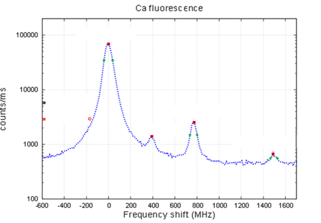
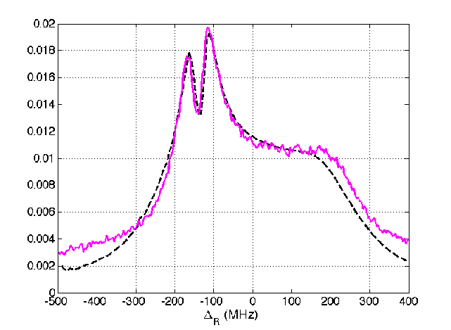
A typical fluorescence spectra from a warm ion cloud is shown in Figure 6, where several distinct features appear. In this case, only one cooling laser is applied, co-propagating with the repumping laser beam. The shape of this Doppler-broadened spectrum can be explained by the dark resonance generated from the simultaneous excitation of the 866-nm and 397-nm transitions at Raman resonance, responsible for the double-peak maximum Lisowski et al. (2005). The large step-like Doppler broadening can be fully reproduced by numerical simulations when the motion of the ions is described by an harmonic oscillation along the laser axis Champenois and et al. (2012).

When laser cooling is efficient enough to compensate the influence of rf heating in the quadrupole trap, a phase transition to a correlated phase (liquid or crystal) Hornekær and Drewsen (2002) can be observed by a dip in the fluorescence spectra and/or by a modification of the shape of the cloud on the camera. When in crystal or liquid phase, the cloud forms a characteristic ellipse whose aspect ratio is controlled by the aspect ratio of the potential and the ion density by the rf pseudo-potential. Comparing pictures of cold clouds in the same rf electric field is then an easy way to compare number of trapped ions as the measurement is independent of the temperature of the ions and the laser detuning.
4.4 Transport
One of the experimental challenges of this device is the achievement of a 100%-transport of a large ion cloud between the different zones of trapping. Moreover, the ions must gain as little energy as possible throughout this transfer. Similar experiments have been carried out in micro-traps, where single ions in the vibrational ground state are shuttled in order to demonstrate scalable architectures in quantum information processing Kielpinski et al. (2002). Different groups have recently demonstrated diabatic transport of single ions in micro-fabricated traps, preserving the motional state of the ions Bowler et al. (2012); Walther et al. (2012). Even though objectives and limiting conditions are very similar in our device, the realization is completely different. We aim to transfer a large 3D-ion cloud, over a distance of tens of millimeters, by actuating only three DC-electrodes and eventually the rf potential. The large dimensions of the ion cloud and the trap itself imply the use of much larger rf and DC voltages than in micro-traps. Similar to micro-traps, DC-voltage switching times are limited by the finite bandwidths of the employed DC drives.
Actually, two conditions are imposed onto the potential during the transport: The axial trapping must not be modified during the transport and the position of the minimum of the potential well, follows a given shape, known as the gate function Hucul et al. (2008). If both conditions are fulfilled, the energy gain of a single ion due to the transport can be analytically calculated for a given gate function and a given gate duration Reichle et al. (2006). While the second condition is easily achieved, the first one can not be satisfied in our set-up due to the large distances between adjacent DC electrodes. As a consequence the secular frequency of the axial potential experiences a large variation during the transport. To investigate how this variation affects the transport, a numerical code is used, as an analytical approach is not possible. The code uses realistic trap potentials given by SIMION8.1 http://www.simion.com (2011) to study the transport of ion clouds in our double trap system. It allows to explore the effects on the transport of many experimental parameters, as a ’gate’ deformation due to bandwidth of the power supply, or the effect of time discretization due to the type of Digital-to-Analog-Converter used to generate the waveforms Pedregosa-Gutierrez and et al. (2013).
Preliminary experiments of shuttling between both parts of the quadrupole trap are very promising. Transfer efficiencies of 100% have been achieved for clouds of about 10000 ions. Experiments are ongoing to study the impact of several trapping parameters before transferring ions to the multipole trap.
5 Perspectives
We have recently set up a new trapping device for the study of the dynamics and thermodynamics of large ion clouds. Our aim is to trap clouds composed by more than one million ions. Different features are of interest in this device. Optimization of the experimental parameters includes the investigation of transport properties between different trapping zones. Optimal control protocols might be the solution to shuttle the complete set of trapped ions without energy gain. The investigation of the shape and structure of a large ion cloud in a multipole trap will give insight into the micromotion influence, and the eventual creation of a tube-like structure. This latter constitutes a quasi-2D structure, and may serve as a model system for new applications.
References
- Prestage et al. (1989) J. Prestage, G. Dick, and L. Maleki, J. Appl. Phys. 66, 1013 (1989).
- Gerlich (1992) D. Gerlich, Advances in Chemical Physics Series 82 (1992).
- Wester (2009) R. Wester, Journal of Physics B: Atomic, Molecular and Optical Physics 42, 154001 (2009),
- Prestage and Weaver (2007) J. Prestage, and G. Weaver, Proceedings of the IEEE 95, 2235 (2007).
- Okada et al. (2007) K. Okada, K. Yasuda, T. Takayanagi, M. Wada, H. A. Schuessler, and S. Ohtani, Phys. Rev. A 75, 033409 (2007).
- Okada et al. (2009) K. Okada, T. Takayanagi, M. Wada, S. Ohtani, and H. A. Schuessler, Phys. Rev. A 80, 043405 (2009).
- Champenois (2009) C. Champenois, Journal of Physics B: Atomic, Molecular and Optical Physics 42, 154002 (2009),
- Hornekær and Drewsen (2002) L. Hornekær, and M. Drewsen, Phys. Rev. A 66, 013412 (2002).
- Dubin and O’Neil (1999) D. H. E. Dubin, and T. M. O’Neil, Rev. Mod. Phys. 71, 87 (1999).
- Calvo et al. (2009) F. Calvo, C. Champenois, and E. Yurtsever, Phys. Rev. A 80, 063401 (2009).
- Marciante et al. (2010) M. Marciante, C. Champenois, A. Calisti, J. Pedregosa-Gutierrez, and M. Knoop, Phys. Rev. A 82, 033406 (2010).
- Marciante et al. (2012) M. Marciante, C. Champenois, A. Calisti, and M. Knoop, Applied Physics B: Lasers and Optics 107, 1117 (2012),
- Champenois et al. (2010) C. Champenois, M. Marciante, J. Pedregosa-Gutierrez, M. Houssin, M. Knoop, and M. Kajita, Phys. Rev. A 81, 043410 (2010).
- Li et al. (2012) T. Li, Z.-X. Gong, Z.-Q. Yin, H. T. Quan, X. Yin, P. Zhang, L.-M. Duan, and X. Zhang, Phys. Rev. Lett. 109, 163001 (2012),
- Marciante et al. (2011) M. Marciante, C. Champenois, J. Pedregosa-Gutierrez, A. Calisti, and M. Knoop, Phys. Rev. A 83, 021404 (2011).
- Reuben et al. (1996) A. J. Reuben, G. B. Smith, P. Moses, A. V. Vagov, M. D. Woods, D. B. Gordon, and R. W. Munn, Int.J. Mass Spectrom. Ion Processes 154, 43 (1996)
- Pedregosa et al. (2010) J. Pedregosa, C. Champenois, M. Houssin, and M. Knoop, Int.J. Mass Spectrom. 290, 100 (2010)
- Alheit et al. (1996) R. Alheit, S. Kleineidam, F. Vedel, M. Vedel, and G. Werth, Int.J. Mass Spectrom. Ion Processes 154, 155–169 (1996).
- Gulde et al. (2001) S. Gulde, D. Rotter, P. Barton, F. Schmidt-Kaler, R. Blatt, and W. Hogervorst, Appl. Phys. B 73 (2001).
- Lucas et al. (2004) D. Lucas, A. Ramos, J. Home, M. McDonnell, S. Nakayama, J.-P. Stacey, S. Webster, D.N.Stacey, and A. Steane, Phys.Rev. A 69, 012711 (2004).
- Lisowski et al. (2005) C. Lisowski, M. Knoop, C. Champenois, G. Hagel, M. Vedel, and F. Vedel, Appl. Phys. B 81, 5 (2005).
- Champenois and et al. (2012) C. Champenois et al., in preparation.
- Kielpinski et al. (2002) D. Kielpinski, C. Monroe, and D. Wineland, Nature 417, 709 (2002).
- Bowler et al. (2012) R. Bowler, J. Gaebler, Y. Lin, T. R. Tan, D. Hanneke, J. D. Jost, J. P. Home, D. Leibfried, and D. J. Wineland, Phys. Rev. Lett. 109, 080502 (2012),
- Walther et al. (2012) A. Walther, F. Ziesel, T. Ruster, S. T. Dawkins, K. Ott, M. Hettrich, K. Singer, F. Schmidt-Kaler, and U. Poschinger, Phys. Rev. Lett. 109, 080501 (2012),
- Hucul et al. (2008) D. Hucul, M. Yeo, W. Hensinger, J. Rabchuk, S. Olmschenk, and C. Monroe, Quant. Inf. Comp. 8, 501 (2008).
- Reichle et al. (2006) R. Reichle, D. Leibfried, R. Blakestad, J. Britton, J. Jost, E. Knill, C. Langer, R. Ozeri, S. Seidelin, and D. Wineland, Fortschritte der Physik 54, 666 (2006)
- http://www.simion.com (2011) http://www.simion.com
- Pedregosa-Gutierrez and et al. (2013) J. Pedregosa-Gutierrez et al., in preparation.