Generation of high-purity higher-order Laguerre-Gauss beams at high laser power
Abstract
We have investigated the generation of highly pure higher-order Laguerre-Gauss (LG) beams at high laser power of order 100 W, the same regime that will be used by 2nd generation gravitational wave interferometers such as Advanced LIGO. We report on the generation of a helical type LG33 mode with a purity of order 97 % at a power of 83 W, the highest power ever reported in literature for a higher-order LG mode.
pacs:
04.80.Nn, 95.75.Kk, 42.60.PkIntroduction The generation of Laguerre Gauss (LG) optical beams has significantly gained interest in recent times. LG modes present in fact several unusual features that make them suitable for a wide range of applications. In physics for example, donut-shaped LG beams confine particles in optical traps lg:mot ; lg:dipole or speed-up charged particles in particle accelerators lg:acc ; higher-order multi-ringed LG beams form toroidal traps for Bose-Einstein condensates lg:bec ; LG beams act as optical spanners transferring their orbital angular momentum to spin macroscopic particles lg:span . In the last years, use of LG beams has been reported in the most diverse areas of science, some examples are material processing lg:matproc , microscopy lg:micro , lithography lg:lith , motion sensors lg:sens , biology lg:biol , biomedics lg:biom .
Higher-order helical type LG modes have been also proposed as upgrades to the readout beams of 2nd generation gravitational wave (GW) interferometers such as Advanced LIGO aligo and Advanced VIRGO avirgo , and are currently baselined for the Einstein Telescope ET . The wider, more uniform transverse intensity distribution of a subset of these beams, compared to the currently used LG00 fundamental mode, can effectively average over the mirror surface fluctuations, to mitigate the effects of brownian motion of the mirror surfaces on the detector GW sensitivity Mours06 ; Vinet09 ; Vinet10 . Using LG modes can also lead to a reduction of thermal effects such as distortions in the mirror substrates, when operating at the high laser power regime envisioned for these detectors Vinet07 . Theoretical studies have initially proven the compatibility of LG modes with the control schemes commonly employed, and identified the LG33 beams as a good trade-off between mirror thermal noise suppression and beam clipping losses Chelkowski:PRD . Subsequent laboratory experiments have then demonstrated the generation of LG modes at the required purity, and the possibility of implementing interferometric measurements using LG beams Fulda:PRD ; granata .
One crucial step into a realistic implementation of LG modes in GW interferometers is to demonstrate the generation of such beams at the high power levels of order 100 W foreseen by next generation detectors. High power LG beams should also comply with the stringent requirements that current GW laser sources have successfully achieved, and present comparably high levels of purity, stability and low noise ref:aLIGO:PSL ; ref:aLIGO:PSL2 ; ref:aLIGO:PSL3 . Generation of LG beams of order tens of W has been reported in literature lg_high:1 ; lg_high:2 ; lg_high:3 ; lg_high:4 , although for different types of applications and limited to lower order donut-shape LG01 beams only. These beams do not meet the requirements discussed above and furthermore are based on beam shaping techniques which have little adaptability and are hardly exportable to higher-order modes or to more generic applications.
We have investigated the generation of higher-order LG modes at the high laser power regime required for operating 2nd generation GW interferometers at full sensitivity. The experiment is based on a beam preparation method originally developed by some of the authors at low power Fulda:PRD and potentially scalable to full scale interferometers. Our investigation aimed not only to generate higher-order LG beam at the highest possible laser power, mode purity and conversion efficiency, but also to identify potential limits of the technology. In this letter we present our experiment’s details and discuss the results. We stress that, due to the simplicity of the experimental scheme, this method is adaptable to a variety of applications, therefore the presented results are potentially relevant to a broader audience than the GW community.
LG modes: LG modes are a complete and orthogonal set of solutions for the paraxial wave equation. The complex amplitude of a helical type LGpl mode, with radial and azimuthal indices and , is usually described as Lasers :
| (1) | |||||
Here are cylindrical-polar coordinates, is the wavenumber, the beam radius, the radius of curvature of the beam wavefront, the Gouy phase, and are the generalised Laguerre polynomials. LG beams are axisymmetric and have spherical wavefront, so they are natural eigenmodes of optical systems whose optical surfaces are spherical and whose symmetry is cylindrical. The order of a LG mode is given by the number : when circulating in optical resonators, modes of the same order experience same resonance conditions, due to the phase term, so the cavity is degenerate for this family of modes. The term is what gives LG modes their characteristic ringed shape, while the azimuthal phase dependence is responsible for their orbital angular momentum, per photon.
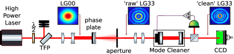
The experiment A sketch of the experimental setup is presented in Fig. 1. A high power, ideally pure fundamental mode laser beam is mode-matched to a desired waist size via a telescope, and then sent on a diffractive phase plate, an etched glass substrate with varying thickness which can imprint the LG33 spiralling phase pattern onto the wavefront of the input beam. The diffraction orders are separated with an aperture, and the main diffracted beam, a composite beam with a dominant LG33 over a background of higher-order modes of minor intensity, is then injected to a linear mode cleaner (MC) cavity, which is alternatively used to analyse the mode content of the input beam itself (scan mode) or to spatially filter out non order 9 LG modes (locked mode) to enhance the mode purity of the LG33 beam generated in transmission. This is eventually recorded by means of a high dynamic range photodiode, for measurement and control purposes, and by a CCD camera, for off-line analysis. Light power measurements are performed at different stages along the optical setup, namely before and after the phase plate, at the MC input and, when the MC cavity is locked, both in reflection and in transmission from the cavity. Similarly, images of the beam intensity distributions are taken at analogous positions for mode content analyses.
The high-power laser source is the Reference System for the Advanced LIGO pre-stabilised laser (PSL) ref:aLIGO:PSL ; ref:aLIGO:PSL2 ; ref:aLIGO:PSL3 and it is located at the Hannover labs where this experiment was performed. The PSL consists of a 2 W Nd:YAG non-planar ring oscillator, two stages of amplification (up to 35 W and 200 W respectively), and a ring cavity at the output, which provides filtering for beam’s spatial profile, pointing and power fluctuations. The output is a 140 W, 1064 nm, continuous wave, 99.5% pure LG00 beam.
The phase plate mode conversion method ref:phaseplate was chosen amongst other successful techniques ref:astigmatic ; ref:hologram ; ref:SLM for the compatibility of passive glass components with the high power regime to be tested in this experiment, and for the relative simplicity of implementation. Our phase plate is a 3 mm thick fused silica substrate with , 7 m side etched pixels, with 8 levels of etching depth resolution 111The phase plate was manufactured by Jenoptik GmbH based on a custom design by some of the authors fulda:13 . . The etched grating phase pattern reproduces the spiralling helical LG33 mode phase structure. On top, a 2.3 mrad angle blazed grating pattern is superimposed to separate the main diffraction order beam from unmodulated residuals of the LG00 mode ref:hologram . FFT beam propagation methods and modal analysis of the beam in the far field were used to estimate the efficiency of this phase plate design in the conversion from LG00 to LG33, which is in the region of 75% depending on the correct size and relative alignment of the incident beam with respect to the phase plate itself fulda:13 . To avoid having light reflected towards the laser, a 1064nm anti-reflective coating was deposited on both surfaces of the phase plate. Measurements showed that about 95% of the light power successfully transmits into the main diffraction order beam, about is dispersed in higher diffraction orders and less than 0.2% is reflected towards the laser source.
The MC is a 21 cm long, plano-concave linear cavity, with 1” fused silica mirrors glued to the ends of a rigid Al spacer. Highly-reflective coatings () were deposited on the mirror substrates in a single coating run, aiming for a nominally impedance matched, maximised transmission cavity. The MC has stability parameter , Free Spectral Range = 714 MHz, measured finesse . Its microscopic length is controlled via a PZT located between the spacer and the input mirror. The error signal for the feedback control is generated by dithering the input mirror position with the PZT and then extracted from the light transmitted by the cavity.

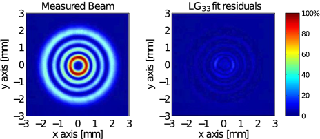
Mode matching of the LG beam generated by the phase plate to the MC eigenmode is non trivial and proved crucial to the successful operation of the cavity. Since conventional beam profilers do not usually resolve LG modes, we first recorded the beam intensity profile with a CCD camera placed along the beam path, then the images were analysed using customised fitting scripts SIMTOOLS which automatically identify the dominant LG33 mode and estimate the beam radius at the given position. Subsequent adjustments of the lenses rapidly led to match the beam waist parameters to within few m from the aimed value, in this case =m. In full scale GW interferometers, acceptable matching errors are of order 1%. Our result shows that mode matching of higher-order LG beams can be performed with comparable accuracy. An example of this analysis is given in Fig. 2.
We used measurements of the light transmitted by the MC as a function of the cavity length (cavity scans) to investigate the mode content of the beam produced by the phase plate, as in the example in Fig. 3. The relevant non order 9 modes were first identified via inspection of the CCD images, then their amplitude, usually a few % of the total power, and the exact mode content of the overall beam could be reproduced with and compared to numerical simulations ref:FINESSE . On average, the fraction of the beam power in order 9 modes is ()%, in agreement with the FFT model prediction fulda:13 .

Results The measurement procedure described above was repeated at progressively increasing input laser power, until the maximum available power was injected on the phase plate. Increasing the laser power stepwise allowed not only for a prevention of damage caused by high powers but also for identifying the potential rise of power-dependent dynamics and potential shortcomings from thermal effects or intra-cavity beam distortions.
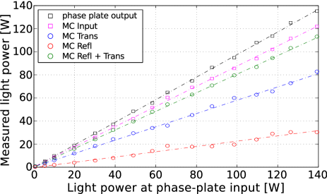
We show the main results of this experimental campaign in Fig. 4, where we plot the light power measured at different locations along the setup as a function of the incident LG00 beam power. First, the linear response of the power transmitted from the phase plate indicates that no effects such as light absorption are arising in the phase plate as the power scales up. We also plot for completeness the same beam when it is propagated to the input of the MC. The 7% reduction in power is consistent with losses likely arising in the intermediate auxiliary optical components and with uncertainties in the measurement calibration 222The error in the calibration of each measurement curve is of order 5% and depends on the beam size at the specific measurement position, on the auxiliary components utilised in each case and on the instruments themselves.. The most notable results in Fig. 4 are the measurements of the light power reflected and transmitted by the MC when this is resonant to order 9 modes. Also in this case the system response is largely linear: the MC length could be locked to the resonance up to full power, for a maximum 83 Wclean LG33 mode transmitted from the MC when a 122 W raw LG beam was injected at input.
To identify potential power-dependent degradations in the mode content of the generated beam, cavity scan analyses were made at every laser power level. The non order 9 content increased by no more than 5% at maximum power, confirming that expected heating processes are arising in some component of the beam generation path, however at a scale which is reasonably small for this type of setup. Even so, the structure of the LG33 output beams did not degrade up to the highest power levels, as shown in the example in Fig. 5 where we plot the intensity profile of the 83 W transmitted by the MC.
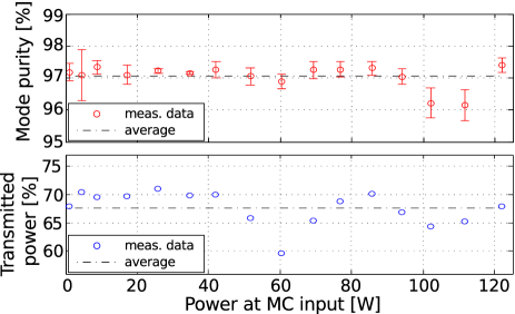
We assess the purity of the clean LG33 beam as the fraction of power in the beam which is in the desired mode and estimate it via the squared inner product between the theoretical LG33 amplitude distribution and the one measured with the CCD camera, 333We note that since the CCD measures beam intensities, this measurement is in principle degenerate for beams with radial index and azimuthal indices .. Results are shown in Fig. 6 (top) as a function of the correspondent LG33 beam power. Over the range of investigation, the LG33 mode purity is above 95%, and no clear trend or degradation is observed. In Fig. 6 (bottom) we show the fraction of the injected light power which is transmitted by the resonant MC cavity. On average, 68% is transmitted into a pure LG33 beam, for a LG33 MC cavity throughput about 90% Also here, no trend can be observed. Taking into account losses in the rest of the apparatus, the overall LG00 to LG33 conversion efficiency is about 59%.
Summary and conclusions Our experimental investigation into the generation of higher-order LG beams at high laser power proved successful: a 83 W LG33 beam with purity of order 97% was obtained from a W LG00 laser beam, sent through a phase plate and a linear cavity. To our knowledge at the time of writing, this is the highest power ever reported for a higher-order LG beam. As a by-product, we have also shown that profiling of LG beams can be performed at the same level of accuracy commonly achieved with LG00 beams.
The beam generation method seems viable for high power applications. The system response was mostly linear over the entire range of investigation. The conversion efficiency, here partly limited by losses in auxiliary optics, can be easily improved with an engineered design of the conversion apparatus, up to a maximum set by the conversion efficiency of the phase plate design. Stability and noise performances were not investigated in this study.
In this work, we have described a method to create a user-defined LG mode from a highly stable, high-power laser. We have successfully demonstrated that this technique creates modes of high purity with a good conversion efficiency and is compatible with common setups used for the laser pre-stabilisation and injection to GW interferometers. This is an important step towards demonstrating technical readiness of LG modes for use in high-precision interferometry and in particular for future GW detectors such as the Einstein Telescope, as well as for the many other areas of science and technology where LG modes have recently found successful application.
Acknowledgements This work was funded by the “Science and Technology Facilities Council” (U.K.) and the “Volkswagen Stiftung” (Germany). C.B. acknowledges financial support by the “Hannover School of Lasers, Optics and Space-Time Research”. This document has LIGO laboratory document number LIGO-P1300012-v2.
References
- (1) M.J. Snadden et al, J. Opt. Soc. Am. B 14, 544 (1997)
- (2) T. Kuga et al, Phys. Rev. Lett. 78, 4713 (1997)
- (3) Y. Liu et al, N.I.M. in Phys. Res. A 424, 296 (1999)
- (4) E.M. Wright et al, Phys. Rev. A 63, 013608 (2000)
- (5) S. Franke-Arnold et al, Laser Phot. Rev. 2, 4, 299 (2008)
- (6) A.V. Nesterov et al, J. Phys. D 33, 1817-1822, (2000)
- (7) T. Züchner et al, Angew. Chem. Int. Ed. 50, 5274 (2011)
- (8) R. Dorn et al, Phys. Rev. Lett. 91, 233 901 (2003)
- (9) S. Ando, Proc. INSS Conference, p.106 (2009)
- (10) A. Lafong et al, Opt. Expr. 14, 7, 3065 (2006)
- (11) R.Dasgupta et al, J. Biomed. Opt. 15(6), 065010 (2010)
- (12) G.M. Harry , Class.Quant.Grav. 27, 084006 (2010)
- (13) T. Accadia et al, Class.Quant.Grav. 28, 114002 (2011)
- (14) B. Sathyaprakash et al, Class.Quant.Grav. 29, 12, 124013 (2012)
- (15) B. Mours et al, Class.Quant.Grav. 23, 5777 (2006)
- (16) J.-Y. Vinet, Living Rev. Relativity 12, 1 (2009)
- (17) J.-Y. Vinet, Phys. Rev. D 82, 042003 (2010)
- (18) J.-Y. Vinet, Class. Quant. Grav. 24, 3897 (2007)
- (19) S. Chelkowski et al, Phys. Rev. D 79, 122002 (2009)
- (20) P. Fulda et al Phys. Rev. D 82, 012002 (2010)
- (21) M. Granata et al, Phys. Rev. Lett. 105, 231102 (2010)
- (22) B. Willke, Laser Phot. Rev. 1-15 (2010)
- (23) L. Winkelmann et al, App. Phys.B, 102, 3, 529 (2011)
- (24) P. Kwee et al, Opt. Expr. 20, 10, 10617 (2012)
- (25) G.Y. He et al, Laser Physics, Vol. 22, N 8, 1275 (2012)
- (26) G. Machavariani et al, Opt. Lett., 32, 11, 1468 (2007)
- (27) M. Meier et al, Appl. Phys. A 86, 329 (2007)
- (28) M. Okida et al, Optics Express, 15, 12, 7616 (2007)
- (29) C. Bond et al, Phys. Rev. D 84, 102002 (2011)
- (30) S. A. Kennedy et al., Phys. Rev. A 66, 043801 (2002).
- (31) J. Courtial et al Opt. Commun. 159, 13 (1999)
- (32) J. Arlt et al, J. Mod. Opt. 45, 1231 (1998)
- (33) N. Matsumoto et al, J. Opt. Soc. Am. A 25, 1642 (2008)
- (34) P. Fulda et al, Phase plate design for Laguerre-Gauss mode conversion, in preparation
- (35) SimTools, available at www.gwoptics.org/simtools/
- (36) A. Freise et al, Class.Quant.Grav. 21, S1067 (2004), also available at www.gwoptics.org/finesse/