HEROICA: an Underground Facility for the Fast Screening of Germanium Detectors
Abstract
An infrastructure to characterize germanium detectors has been designed and constructed at the HADES Underground Research Laboratory, located in Mol (Belgium). Thanks to the 223 m overburden of clay and sand, the muon flux is lowered by four orders of magnitude. This natural shield minimizes the exposure of radio-pure germanium material to cosmic radiation resulting in a significant suppression of cosmogenic activation in the germanium detectors. The project has been strongly motivated by a special production of germanium detectors for the GERDA experiment. GERDA, currently collecting data at the Laboratori Nazionali del Gran Sasso of INFN, is searching for the neutrinoless double beta decay of 76Ge. In the near future, GERDA will increase its mass and sensitivity by adding new Broad Energy Germanium (BEGe) detectors. The production of the BEGe detectors is done at Canberra in Olen (Belgium), located about 30 km from the underground test site. Therefore, HADES is used both for storage of the crystals over night, during diode production, and for the characterization measurements. A full quality control chain has been setup and tested on the first seven prototype detectors delivered by the manufacturer at the beginning of 2012. The screening capabilities demonstrate that the installed setup fulfills a fast and complete set of measurements on the diodes and it can be seen as a general test facility for the fast screening of high purity germanium detectors. The results are of major importance for a future massive production and characterization chain of germanium diodes foreseen for a possible next generation 1-tonne double beta decay experiment with 76Ge.
keywords:
Cryogenic Detectors; Gamma Detectors; HPGe Detectors1 Introduction
The GERDA [1]-[2] (GERmanium Detector Array) experiment, in operation at Laboratori Nazionali del Gran Sasso (LNGS) of INFN has been designed to search for the neutrinoless double beta decay () of 76Ge using germanium detectors. The diodes are made of isotopically modified material, enriched to about 88% in 76Ge, and are operated without encapsulation in a Liquid Argon (LAr) cryogenic bath. The experiment is currently running its Phase I with coaxial germanium detectors which were used by the former HdM [3] and IGEX [4] double beta decay experiments. Further information on the construction and commissioning of GERDA, its physics goals and the first results can be found elsewhere [2, 5].
While GERDA Phase I is running, the collaboration is preparing a new phase to double the active detector mass and, with the help of new LAr veto techniques, to reduce further the overall background aiming at a higher signal sensitivity. For the production of new detectors, 35 kg of germanium material equally enriched in 76Ge, are available for the GERDA experiment. Broad Energy Germanium detectors (BEGe) [6] have been largely studied for their excellent energy resolution and their enhanced pulse shape properties which allow to reduce further the background discriminating multiple from single site events [7]. Both GERDA and MAJORANA [8] collaborations have selected similar detector technologies for their physics goals. Concerning GERDA, the crystal growth has been performed at Canberra Oak Ridge (USA) [9], while the diode production was performed at Canberra, Olen (Belgium) [9].
In recent years, a pilot run with isotopically modified germanium detectors (i.e. depleted in the 76Ge content) has been performed by the GERDA collaboration. The procedure allowed to test the production of commercially available germanium detectors using custom material and to define the quality acceptance protocol for the experiment [10].
Special efforts in terms of logistics were taken during the different production phases in order to minimize the exposure of the enriched germanium material to cosmic radiation. Cosmogenically produced radio-isotopes include 68Ge and 60Co that become a serious hazard by mimicking neutrinoless double beta decay of 76Ge in germanium detectors. The low contamination requirement has been assured by storing the crystals in a container equipped with shielding layers of steel and water during transport between the USA and Europe. Moreover, the crystal first, and the diodes afterwards, are always stored in underground locations close to the production plants.
The search for a clean underground site where to perform the full set of characterization measurements on the newly produced diodes before shipping them to their final destination at the LNGS, has been successful with the selection of the HADES (High Activity Disposal Experimental Site) Underground Research Laboratory. The place is as close as possible to the diode manufacturer (), and besides hosting the characterization measurements, it is used to store the crystals and the diodes during production over night and during weekends.
The present paper starts with a description of the unique characteristics of HADES as a low background site for detector testing and low activity measurements. After a short introduction to the diodes acceptance protocol, the infrastructure (electronics, computing and DAQ resources), the characterization setups and their performances are described. Furthermore, the overall performances of the acceptance tests are reviewed and the prospects for the characterization of the full batch of detectors to be produced for GERDA are given.
2 The HADES Underground Research Laboratory
HADES is a semi-deep underground laboratory [11] built in the frame of the Belgian research programme regarding the geological disposal of radioactive waste on the premises of the Belgian Nuclear Research Center SCK CEN (Studie Centrum voor Kernenergie Centre d’Etude de l’Energie Nucléaire) in Mol (Belgium). Since 1997 HADES is managed by EURIDICE (European Underground Research Infrastructure for Disposal of nuclear waste In Clay Environment) as a research facility [12] and not as a disposal site. As shown in Figure 1, the underground laboratory is located at about below ground in the "Boom clay" layer. The main purpose of the laboratory is to examine the possibility of constructing a high level nuclear waste repository at such a depth and conduct various in-situ experiments with the aim of characterizing geological properties of the clay. The underground tunnel is reachable via two shafts. The Institute for Reference Material and Measurements (IRMM), part of the European Commission’s Joint Research Centre (JRC), operates a dedicated Ultra Low-level Gamma-ray Spectrometry (ULGS) facility at one end of the HADES tunnel [13].
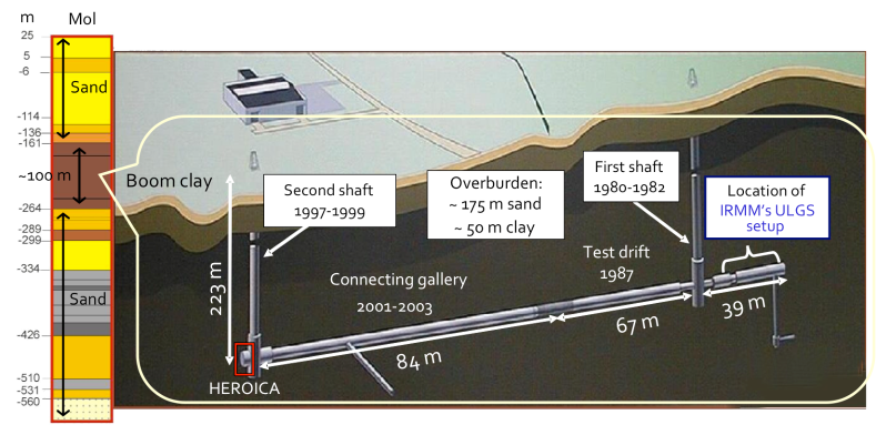
An area of about at the opposite end of the gallery has been assigned to the HEROICA (Hades Experimental Research Of Intrinsic Crystal Appliances) project. The area has been equipped with dedicated setups, DAQ systems and networking for data transfer to outside institutes. In order to minimize microphony on the highly sensitive devices a new damped pavement (10 mm thick) has been installed. Moreover, all electronic devices have been grounded in order to minimize noise and cross-talk effects.
The sand and clay overburden corresponds to about 500 m water equivalent and cuts the muon flux and secondary hadronic showers down to which is a reduction of about four orders of magnitudes with respect to the ground level [13]. The radon concentration in the HADES tunnel is low; the average value collected over a fortnight test measurement using a Radim 3A [14] detector is , with oscillations between and . Such a low radon level is due to low uranium concentration in the surrounding material and to a constant ventilation of the underground areas with an air flux of about . Even though the HEROICA detector shielding does not include an active anti coincidence muon veto and nitrogen flushing in order to further minimize the impact of radon (and its daughters), the obtained background is highly satisfactory in terms of the HEROICA acceptance tests and for storage of the enriched germanium material. Indeed, the HEROICA setups are designed for the characterization of germanium detectors using strong calibration sources. On the contrary, low-level activity IRMM detectors at ULGS site are designed to measure low-activities in material samples and thus require the best achievable background suppression applying different shielding techniques.
3 The Germanium Detector Specifications and Measurement Protocol
The acceptance tests aim to verify the specifications given by the manufacturer, to extract important detector parameters (such as the active mass and dead layer thickness) and to determine the optimal operational conditions. Since the detectors will be operated "naked" in an underground experiment, this is the only chance to fully characterize the detectors before dismounting them from their vacuum cryostat and deploy them in the GERDA LAr cryostat (as described in [2])
As mentioned above, a dedicated run with isotopically modified germanium detectors, depleted in the 76Ge content, has been very important to optimize the acceptance test protocol [10].
The operational parameters to be determined are:
-
•
depletion voltage;
-
•
energy resolution;
-
•
leakage current.
The test is performed to study the charge collection features of each diode and determine
-
•
the detector active volume and mass;
-
•
the dead layer thickness and uniformity over the surface.
Finally, the pulse shape characteristics of the diodes have to be studied and their efficiency for identification of single-site events ( candidates) and rejection of multiple-site events (background) has to be determined: the study allows to refine background reduction techniques for double beta decay searches of 76Ge [2], [15].
According to the contracts and agreements between the GERDA collaboration and Canberra Industries, the new detectors are delivered to HADES mounted in a vacuum cryostat and assembled in the Canberra Dip-Stick vertical dewar [16]. The dewar is positioned on a moving cart which allows to move the detectors within the test area and to position them on the measurement stands.
The BEGe specifications are the following:
-
•
crystal diameter ;
-
•
crystal length , potentially up to ;
-
•
detector mass ;
-
•
energy resolution (FWHM) better than 2.3 keV at the 1332 keV 60Co peak;
-
•
leakage current below ;
-
•
full depletion voltage below 4 kV.
4 The HEROICA Project
Two different mechanical setups have been designed for the tests of the diodes:
-
•
a measurement table which allows: 1) to shield the diode from the environmental background and protect the operators from the radiation created by the simultaneous use of several calibration sources in the same area; 2) to place the calibration sources (with or without collimators) in a few fixed positions around the detector;
-
•
a setup with a movable arm, motor controlled, which allows to perform a top and lateral detector surface scans with a collimated source.
In the following sections both measurement setups will be described in detail.
4.1 The Fixed Calibration Measurement Setup
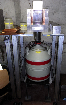
The characterization of several standard parameters describing the overall performance of germanium detectors such as depletion voltage, energy resolution, average dead-layer thickness and pulse shape performance can be done with sources positioned at a fixed distance from the detector. For this purpose, the HEROICA infrastructure includes two setups that consist of a table with appropriate shielding and source holders. The tables have adjustable height and a bay which allows to park a movable cart carrying a cryogenic dewar and the dip-stick cryostat at the center of the setup (see Figure 2, left).
The passive shield is built from lead bricks, so that the shield thickness is 5 cm. Three additional layers of copper plates (each 1 cm thick) are inserted in the inner part of the shielding castle. The shielding is completed with a 1 cm copper plate on the top. A cross section of the shielding castle can be seen in the left picture of Figure 2.
Thanks to the shielding, the exposure of shifters to radiation by a large set of sources used during the long-standing screening activities is significantly reduced. The height of the shielding allows to position sources at distances up to about 20 cm above the detector. As discussed previously, further background suppression by an active muon veto or a radon tight, nitrogen flushed detector chamber is not needed.
4.2 The Automated Scanning System
An automated scanning table has been designed and built to move a collimated source around the detector cryostat. The setup allows to irradiate the detector top and lateral surfaces. All measurements are performed with a 5 MBq 241Am source (see Table 1 for a list of the calibration sources) placed inside a shielding box (), made of copper with a 1 mm collimator hole. The purpose of the measurements is the study of the charge collection efficiency of the diode by looking at the detector response to the source placed on different positions on the top and lateral surfaces. Thanks to the 59.5 keV 241Am photons, which are easily absorbed by the collimator walls, a pencil-like beam is shot on the cryostat and it allows to estimate the diode dimensions.
The collimated source is mounted on an arm which is parallel to the diode top surface. The source can be moved along the arm (i.e. along the top surface of the diode) with a positioning resolution and reproducibility better than 1 mm. Moreover, the arm can be rotated around the crystal cylindrical axis between 0 and 359 degrees in steps of 1 degree.
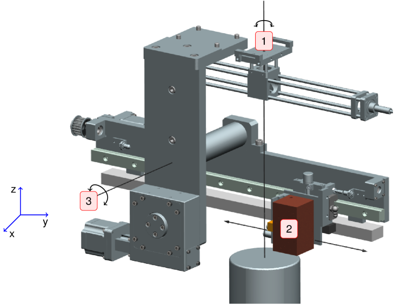
Figure 3 shows a detail of the setup with special emphasis on the main movements. Label 1 shows the possible rotation of the full system around the detector z-axis. The source, mounted inside a copper collimator (label 2) can be moved along the arm holder. By acting on movements, labelled (1) and (2) on Figure 3, it is possible to reach any point on the x-y plane. Finally, movement (3) allows to rotate the source holding arm around the x-axis, thus bringing the arm along the z-axis. In this new position, by acting on movements 1 and 2 it is possible to move the source around the detector lateral surface.
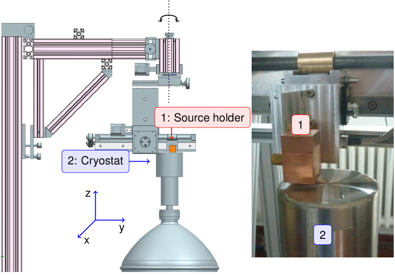
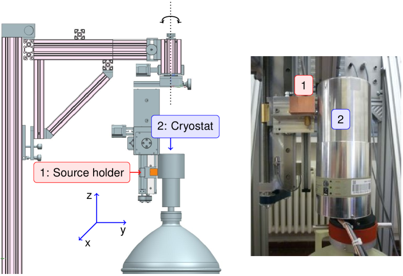
Figures 4 and 5 show the two main apparatus settings while scanning top and lateral surfaces, respectively. In Figure 4, the arm is placed horizontally in the x-y plane, parallel to the top detector surface, and the source holder is positioned on top of the cryostat. While keeping the arm fixed, it is possible to move the source along it, thus performing a scan along a top surface diameter. Since the arm can be rotated around the z-axis (which coincides with the diode axis), it is possible to span various diameters. Moreover, by keeping the source still with respect to the arm, while rotating it around the z-axis, circumferences are spanned on the top surface. The right part of Figure 4 shows in detail the top surface cryostat with the source holder on top of it while a measurement is running.
4.3 Radioactive Sources and Source Holders
A large set of radioactive sources has been provided according to the requirements of the different measurements included in the test protocol. This large number is due to the need to perform a fast screening on a large number of detectors (up to 5 detectors are measured in parallel with a global rate of two diodes fully screened per week). The choice of the source isotope and activity for each measurement is driven by the detector’s properties to be investigated and the acceptable statistical uncertainty of the measurements; the latter is a compromise between DAQ trigger and filter limitations, required measurement time and number of collected events.
Table 1 shows a list of commonly used sources for the standard characterization measurements.
| amount | nuclide | activities | measurements |
| [kBq] | |||
| 5 | 60Co | 3-15 | Resolution, High Voltage Scan, Active Volume |
| 3 | 228Th | 10 | Pulse Shape Analysis |
| 5 | 241Am | 100-500 | Dead Layer, Pulse Shape Analysis |
| 5 | 133Ba | 3-45 | Dead Layer |
| 3 | 241Am | 5000 | Charge Collection |
| 3 | 137Cs | 5-20 | Energy Calibration |
| 1 | 152Eu | 80 | Energy Calibration |
For the automated scanning measurements, a high count rate is required so that even with a collimated source the total net count in the 59.5 keV peak of 241Am is of the order of 103 when measuring for less then 5 minutes in each point. Therefore, an activity of 5 MBq was chosen. For the high voltage scan measurements, a 60Co source of was chosen, which allows to obtain net counts in the two main peaks at 1.1 MeV and 1.3 MeV within a 10 minutes measurement (at each high voltage value). In this way, a complete high voltage measurement lasts less then one day. For the active volume determination, a 60Co source is used, while for the dead layer determination, a 241Am and a 133Ba source are used. For these measurements, a net count of more than in the peaks of interest are required within 1-2 hours. A 228Th source of is used for the pulse shape analysis, which allows to obtain a statistics of about events in the double escape peak (at 1.59 MeV) of the 208Tl 2.6 MeV line with a measurement time of about 8 hours.
For all static measurements, dedicated plexiglass source holders have been procured. They consist of a base, fitting on the cryostat cap so that it is properly centered, and on which it is possible to insert one or a series of different plexiglass pieces with fixed height. In this way, each measurement can be performed with a fixed and reproducible source-to-detector distance.
4.4 Front-End Electronics and Data Acquisition
The detectors under test are connected to three two channel ISEG [17] HV power supplies (mod. 246L), operated and controlled via CANbus [18] interface. The front-end read out is performed with Canberra 2002 CSL charge sensitive preamplifier with RC-feedback preamplifiers (decay time ) including cold FETs. A pulser signal can be fed into a test-input line of the preamplifiers for checking the signal stability over time. Another test-voltage point connected to the preamplifier allows to monitor continuously the leakage current which is subsequently registered by voltage loggers EL-USB-3 from LASCAR [19]. The output signals can be read by two DAQ systems: Multi Channel Analyzer modules by ORTEC and Canberra, and Struck Flash ADCs.
Two different MCA modules are used for the characterization measurements:
The full-registration of the waveforms of single events is performed with two Struck SIS3301 VME FADCs and 2 GHz VME CPUs that are mounted into a Wiener VME crate. Each FADC module accommodates up to eight input channels allowing a sampling-rate of 100 MHz. A pulse is saved with 14-bit resolution, such that it contains up to 128 k samples with a maximum trace-length of 1.28 ms. In order to make full use of the dynamic range, a custom-made amplifier has been installed. Besides the ability of sampling, the Struck FADC allows to apply fast integration and differentiation filters to shape signals and produce energy spectra. Moreover, the FADC works in a dual buffer mode, i.e. the non-active buffer can be read out during data-collection. However, the Struck FADC does not include the synchronization of modules operating in parallel, a usable clock for absolute time estimation of stored traces, and a reliable implementation of a counter used for a correct live time calculation. These tasks are performed by a Field Programmable Logic Array on a custom made VME module [2].
4.5 Electronic Noise Optimization
In order to have an optimal energy resolution and amplitude versus energy (A/E) distribution111The amplitude versus energy (A/E) distribution is used for pulse shape discrimination techniques. is the maximum height of the differentiated input signal, while is the corresponding reconstructed energy. for the BEGe detectors under test, it is essential to operate in a noise-free environment. As mentioned previously, a first step in this direction was the installation of a custom-made 10 mm thick damped pavement to reduce microphonic noise originating from the elevator close to the HEROICA site and from the stainless steel floor and its support structure inside the HADES tunnel. In addition, after the installation of the static source tables and of the first automated scanning table, dedicated noise studies were performed. In the first version of the setup, a periodically modulated signal originating from the scanning table, was detected. During the installation of the second and third scanning tables, a full grounding of all setups and electronics was performed, which significally improved the overall noise. The results are discussed elsewhere [15].
4.6 Networking and Computing Infrastructures
A dedicated network (virtual LAN) has been setup for the computing facilities of the project. A public server (bastion host type) allows to access the internal resources from the outside and provides all network services required by the internal network nodes (DNS, DHCP). The access from/to the Internet is restricted to specific hosts and services and is handled through a firewall administered by the SCKCEN, IT group. A limited number of hosts, one for each participating institute, has been granted authorization for ssh [23] and VNC [24] access to the bastion host. Due to the access restrictions222Access to the area is possible during working days from 7:30 to 16:00 and always supervised by SCK authorized personnel. to the HEROICA experimental area, remote access is crucial for controlling the status of the tests and for the real-time check of the collected data. All data are automatically copied to computing resources hosted at MPIK Heidelberg, during the night. The procedure, besides providing a backup copy of all the data, allows to perform remote analyses.
Concerning the computer infrastructure:
-
•
a bastion host running LINUX Debian 6.0 which acts as a disk server for all data (an array of RAID’5 disks for a total of 14 TBytes), has a local database (PostgreSQL) for monitoring of detectors high voltages, and is used to control the data acquisition;
-
•
a virtual machine running Windows XP which is used to control the scanning tables and to run the Canberra and ORTEC MCA.
-
•
a VME CPU, running LINUX Ubuntu 8.10, used to control the Struck FADC modules.
5 Screening Capacity and Performances
According to the screening protocol, after a new detector is delivered, the following measurements are performed on a static table:
-
•
energy resolution; a run with 60Co at the operational voltage suggested by the producer is taken. The measurement runs for 10 minutes with MCA and FADC histogram mode333In histogram mode only the reconstructed energy spectrum is saved on disk, while the single event pulses are discarded..
-
•
60Co high voltage scan; several runs at different bias voltages are collected and the resolution and peak integral studied as a function of the voltages. The single runs last between 2 and 5 minutes and with a voltage step of 50 V, the scan will last between 5 and 8 hours.
-
•
active volume determination; a long run (about one hour) is performed with a 60Co source at full depletion voltage.
-
•
dead layer measurements; two runs are collected using uncollimated 241Am and 133Ba sources. Depending on the source activity, the runs last one hour for 133Ba and at least two hours for 241Am.
-
•
pulse shape discrimination; a long run with a 228Th source is collected for at least eight hours. The acquisition is performed collecting the full pulse waveform for further analysis.
In a second phase, the detector is moved to the scanning table and the diode charge collection is studied using a collimated 241Am source:
-
•
a full scan on the top surface along two orthogonal diameters is performed. The measurements with MCA data acquisition is taken in steps of 1 mm or less and with a live time of 2 or 3 minutes. The data are used to estimate the diode dimensions and verify charge collection uniformity along the surface. Moreover the measurements are used to align the detector in the analysis reference system.
-
•
a circular scan on the top surface is taken. The source spans two outer circles close to the detector border, two circles in the middle of the diode and one point in the centre of the detector. The measurements are collected with both MCA and FADC (waveform sampling mode) and are used to perform detailed studies on the A/E distribution on the detector top surface.
-
•
one or two linear scanning measurements are performed on the lateral surface. The runs are taken with the MCA data acquisition system and are collected to verify charge collection uniformity on the lateral surface and to check the crystal height.
-
•
a circular scan on the lateral surface is collected. A ring at a fixed height is taken with both MCA and FADC (waveform sampling mode) and is used to check the A/E distribution on the lateral surface.

While a complete discussion of the measurements and the results obtained from the tested diode is the argument of a separate paper [15], the automated scanning tables performances are presented in the following. The setup represent an innovative step compared to the work presented in [10]).
An example of detector response to 241Am photons during a top surface scan can be seen in Figure 6: the histogram reports the 59.5 keV peak count rate as a function of the source position above the detector surface. The collimator is moved along a straight line with 1 mm steps above the detector endcap. Two sets of measurements are presented: for the second set (crosses), the source arm is rotated by 90 degree in the x-y plane with respect to the first set (open circles). The count rate is zero outside the detector active volume and reaches a constant value of about 40 counts/s while on the diode surface. This fast measurement (the exposure is only 90 seconds per point) allows to determine the active detector diameter.
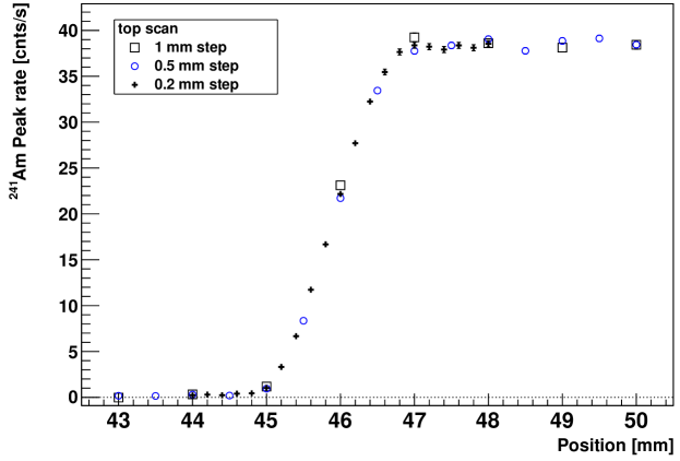
A study of the reproducibility of the source positioning on the detector surface has been performed. Figure 7 shows three sets of measurements taken on the same detector edge with different step size among the source positions: 1 mm, 0.5 mm and 0.2 mm. The integrals of the photon contributing to the 241Am 59.5 keV peak are in remarkable agreement between the different sets of measurements. The source is moved to the same zero position (located outside the detector) before starting each set of measurements.
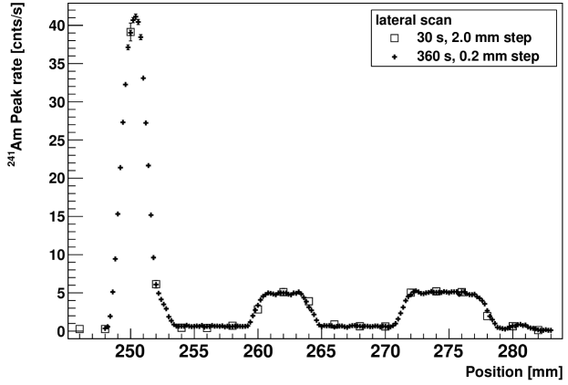
The response of the detector to 241Am photons during a lateral surface scan can be seen in Figure 8: the histogram reports the 59.5 keV peak count rate as a function of the source position along the lateral surface of the detector. The shape of the count rates is completely determined by the structure of the detector holder used to support the diode inside the vacuum cryostat: the strong suppression rate in the regions 252-260 mm and 264-271 mm is indeed due to two reinforcement rings present in the holder mechanics. The reduction of measured count rate is in very good agreement with the holder thickness and geometry provided by the manufacturer.
6 Conclusions
A full infrastructure has been designed, built and commissioned for the acceptance tests of the new, 76Ge enriched, BEGe detectors for the Phase II of the GERDA experiment. The facility has been run at first for a period of five months, in early 2012, on the first seven BEGe prototypes delivered by Canberra. Starting from the end of August 2012 it is working to test the remaining 23 BEGe detectors with an average speed of 2 diodes per week.
The infrastructure has demonstrated an high flexibility and has permitted to collect an enormous amount of information on each tested diode. These pieces of information will be essential in the future application of the characterized diodes in the GERDA experiment.
Acknowledgments
The authors would like to thank the team of EIG EURIDICE for their support during the installation phase and during the running of the project. Many thanks also to the radioprotection services of: SCKCEN, IRMM, University of Tübingen, MPP München and MPIK Heidelberg. Special thanks to the mechanical workshops of INFN Padova, MPIK Heidelberg, Tübingen and IRMM for their commitment during the production and assembly of the setups. Finally, we thank all the members of the GERDA collaboration for their warm support and fruitful discussions.
The project has been supported financially by the German Federal Ministry for Education and Research (BMBF), the German Research Foundation (DFG) via the Excellence Cluster, the Italian Istituto Nazionale di Fisica Nucleare (INFN), the Max Planck Society (MPG), the Swiss National Science Foundation (SNF). The institutions acknowledge also internal financial support.
References
- [1] I. Abt, et al., Letter of Intent to LNGS, see also: [\hepex0404039], GERDA Proposal to LNGS(2004), http://www.mpi-hd.mpg.de/gerda/.
- [2] K. H. Ackermann et al., The GERDA experiment for the search of decay in 76Ge submitted for publication in Eur. Phys. J. C [\hrefhttp://www.arxiv.org/abs/arXiv:1212.4067arXiv/1212.4067]
- [3] Klapdor-Kleingrothaus, et al., Latest results from the HEIDELBERG-MOSCOW double beta decay experiment, Eur. Phys. J. A 12 (2001) 147-154 [\hepph0103062]
- [4] C. E. Aalseth, et al., The IGEX Ge-76 neutrinoless double-beta decay experiment: Prospects for next generation experiments, Phys. Rev D 65 (2002) 092007 [\hepex0202026]
- [5] M. Agostini et al., Measurement of the half-life of the two-neutrino double beta decay of 76Ge with the Gerda experiment, J. Phys. G: Nucl. Part. Phys. 40 (2013) 035110 [\hrefhttp://www.arxiv.org/abs/arXiv:1212.3210arXiv/1212.3210]
- [6] P. S. Barbeau et al., Large-Mass Ultra-Low Noise Germanium Detectors: Performance and Applications in Neutrino and Astroparticle Physics, JCAP 0709:009, (2007), [\nuclex0701012]
- [7] D. Budjáš et al., Pulse shape discrimination studies with a Broad Energy Germanium detector for signal identification and background suppression in the GERDA double beta decay experiment, JINST 4 (2009) P10007.
- [8] D.G. Philips II et al., The MAJORANA Experiment: and ultra-low background search for neutrinoless double-beta decay, [\nuclex1111.5578]
- [9] Canberra, http://www.canberra.com
-
[10]
M. Agostini et al., Procurement, production and testing of BEGe
detectors depleted in 76Ge, Nucl. Phys. B (Proc. Suppl.)
229 (2012) 489.
D. Budjáš et al., Isotopically modified Ge detectors for GERDA: from production to operation, paper in preparation. - [11] EIG EURIDICE (European Underground Research Infrastructure for Disposal of nuclear waste in Clay Environment), http://eee.euridice.be
- [12] See for instance, ESV EURIDICE GIE, Activity Report 2011, and references within, http://www.euridice.be/eng/06publicaties2012.shtm
- [13] E. Andreotti, et al., Status of underground radioactivity measurements in HADES, Proceedings of the 3rd International Conference on Current Problems in Nuclear Physics and Atomic Energy, Kyev, 2011, P601
- [14] Radim 3A, compact Radon Monitor, product of GTAnalytic, http://www.radon.at
- [15] E. Andreotti, A. Garfagnini, W. Maneschg at al., Production and characterisation of 76Ge enriched BEGe prototype detectors for GERDA Phase II, paper in peparation.
- [16] Dip-Stick vertical dewar, 7500SL, product of Canberra USA.
- [17] ISEG Spezialelektronik GmbH. http://www.iseg-hv.com
- [18] Controller Area Network (CAN), ISO 11898-1:2003.
- [19] Lascar Electronics: http://www.lascarelectronics.com/data-logger/.
-
[20]
Canberra Multiport II, Multi Channels Analyzer,
http://www.canberra.com/products/radiochemistry_lab/nim-multichannel-analyzer.asp - [21] ORTEC 926 Multichannel Buffer and ORTEC ASPec-927 Dual Multichannel Buffer, http://www.ortec-online.com/Solutions/multichannel-analyzers.aspx
- [22] T. Kihm et al., A Digital Multichannel Spectroscopy System with 100 MHz Flash ADC module for the GENIUS-TF and GENIUS projects, Nucl. Instr. and Meth. B 498 (2003) 334.
- [23] ssh, Secure SHell network protocol for secure data communication, RFC 4250, 4251, 4252, 4253 and 4254.
- [24] Virtual Network Computing, a graphical desktop sharing system that uses the RFB protocol (remote framebuffer) to remotely control another computer.