Broadband optical isolator in fibre optics
Abstract
We propose a broadband optical diode, which is composed of one achromatic reciprocal quarter-wave plate and one non-reciprocal quarter-wave plate, both placed between two crossed polarizers. The presented design of achromatic wave plates relies on an adiabatic evolution of the Stokes vector, thus, the scheme is robust and efficient. The possible simple implementation using fibre optics is suggested.
pacs:
42.15.Eq, 42.79.-e, 42.81.-i, 78.20.Fm, 78.20.LmKeywords: broadband optical isolator, fibre optics, adiabatic evolution.
1 Introduction
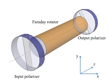
An optical isolator (optical diode) is an optical component that allow the light to pass in one direction but block it in the opposite direction. These devices are commonly used in laser technology to prevent the unwanted backreflections which might be harmful to optical instrumentation. The standard optical isolator, as first proposed by Rayleigh [1], is composed of two polarizers with their transmission axes rotated by with respect to each other and a Faraday rotator. The Faraday rotator is made of a magnetoactive medium which is placed inside a strong magnet. The magnetic field induces a circular anisotropy in the material (Faraday effect), which makes the left and right circular polarizations experience a different refraction index. As a result, the plane of linear polarization travelling through the device is rotated by an angle equal to
| (1) |
where is the induction of the applied magnetic field, is a length of the magnetoactive medium and is the Verdet material constant. Because the Verdet constant depends strongly on the wavelength, so does the rotation angle of the rotator.
The standard optical diode shown in Figure 1 works as follows. The light travelling in the forward direction is first linearly polarized in the horizontal direction by the input polarizer. Afterwards, the Faraday element rotates the polarization by and finally, the light is transmitted through the output polarizer. The light travelling backwards is first linearly polarized at , the Faraday rotator then rotates the polarization by another , meaning the light is now polarized in the vertical direction. Because the input polarizer transmits only horizontal polarization, the light is extinguished. The main drawback of standard isolators is that they work efficiently only for a very narrow range of wavelengths, because of the dispersion of the Faraday rotation angle .
The usual approach seen in commercial broadband isolators is to add the additional reciprocal rotator (e.g. quartz rotator) next to the Faraday rotator. The former element is used to compensate for the dispersion of the Faraday rotator [2, 3, 4, 5, 6]. In the forward direction, the rotation of the two elements add up to a total rotation of , whereas in the opposite direction the rotations subtract and no rotation is experienced by the plane of linear polarization.
Recently we proposed a novel broadband isolator [7], which could be realized with the bulk optics elements. We exploited the analogy in the mathematical description of a quantum two-state system driven by a pulsed laser field and an electromagnetic wave propagating through an anisotropic medium. The technique of composite pulses known from nuclear magnetic resonance (NMR) [8, 9] and quantum optics [10] was applied by us to find conditions for broadband operation of the isolator.
In this article, we propose an alternative realization of the optical isolator which could be suitably implemented in fibre optics. Our approach is based on the adiabatic evolution of the Stokes vector [11, 12] which allows for a broadband performance of the presented isolator.
As high-power fibre lasers are attracting an increasing attention, the development of integrated optical elements for the manipulation of the state of light becomes a crucial point. An all-fibre architecture has the advantage of allowing for an efficient transmission of light without reflections losses on the way (except from an input to a fibre); such losses are a serious problem in bulk optics. As the broadband high-power sources like superluminescent diodes (SLD) or Ti:Sapphire oscillators are broadly used in optical coherence tomography (OCT) [13, 14], characterization of optical components [15] and optical measurements [16], the issue of the efficient broadband isolation in fibres is of increasing importance.
The composition of the manuscript is the following. In section 2 we present the mathematical description underpinning our approach. Section 3 discusses the design of our broadband optical isolator. Then we consider the practical realization of the proposed design in section 4. Section 5 presents the performance of the diode and in the last section 6 we summarize the conclusions.
2 Stokes formalism
Consider the propagation of a plane electromagnetic wave through an anisotropic dielectric medium along the -axis. We assume that there are no polarization dependent losses. Then the equation of motion is given by the torque equation [17, 18, 19, 20, 21]
| (2) |
where is the Stokes polarization vector representing any state of polarization on the Poincaré sphere, and is a birefringence vector of the medium. One can write down Equation (2) in matrix form as
| (3) |
where the matrix is given as
| (4) |
We shall make use of the adiabatic evolution of the Stokes vector. For this purpose, we need the eigenvalues of , which read
| (5) |
with . The eigenvector that corresponds to the zero eigenvalue is extremely simple:
| (6) |
We will call this eigenvector “polarization dark state” in analogy to the stimulated Raman adiabatic passage (STIRAP) process in quantum optics [22, 23, 24]. Assuming that the evolution is adiabatic and that the Stokes polarization vector is initially aligned with the polarization “dark state” , then the Stokes vector will follow this adiabatic state throughout the medium. The evolution of the polarization “dark state” depends on the initial polarization and the spatial ordering of the components of birefringence vector. It will be discussed in detail in the next section.
3 The design of wave-plates
The optical isolator we are going to present requires two crossed polarizers and two achromatic optical elements: a reciprocal (standard) quarter wave plate and a non-reciprocal quarter wave plate. Below we will describe the design in the framework of formalism presented above.
3.1 Reciprocal quarter wave-plate
Let us first analyze the operation of the achromatic reciprocal quarter wave-plate. This problem was recently studied in [25, 26]. The reciprocity of the wave plate comes from the reciprocity of the birefringence vector. This means that when the light travels through the wave plate in the reverse direction, the sign of the birefringence vector is also reversed.
Bearing this in mind, we analyze the evolution of the polarization dark state Equation (6). Let us assume that initially the light is linearly polarized in the horizontal direction, . When precedes and , and the Stokes vector smoothly follows the birefringence vector, the polarization ends up in the right circular polarization state , provided that only is present at the end (e.g. through a large spin rate of the fibre [25, 26]). The process is fully reversible, meaning that if we change the ordering of the birefringence vector components ( now precedes and ), and the Stokes vector is initially aligned along -axis, it adiabatically evolves into state (horizontal linear polarization). The latter holds if only is present at the end. Thus, this arrangement operates as the standard quarter wave plate.
3.2 Non-reciprocal quarter wave-plate
The second case of the non-reciprocal quarter wave plate requires the use of a non-reciprocal birefringent element, which would be sensitive to the direction of propagation of light. It is long known that the magnetic field applied to a magnetoactive medium induces a circular birefringence which makes the left and right circularly polarized light experience different refractive indices resulting in rotation of the plane of linear polarization.
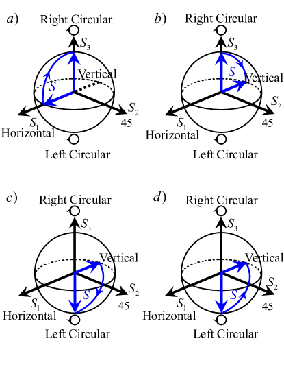
In the forward direction the operation of the element with one of the birefringence components being non-reciprocal is the same as for a reciprocal one: the light initially polarized horizontally is transformed into the right circular polarization state . However, the propagation in the reverse direction is different. If we start with the right circular polarization it evolves into the linear vertical polarization (see Figure 2).
4 Practical implementation
The design of the broadband optical isolator described in section 3 could be conveniently implemented with single-mode optical fibre. The use of fibre-optic isolator is exceedingly attractive for integrated fibre-optic systems as well as high power applications.
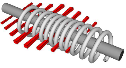
The single-mode fibre has to exhibit both linear and circular birefringence. The first one might be induced by stress applied to a fibre or by external electric field [12, 27]. To induce the circular birefringence one might apply a torsion of the fibre (for the reciprocal effect) or the external magnetic field (through the Faraday non-reciprocal effect). The possible implementation is depicted in Figure 3.
The achromatic wave-plate described in section 3.1 would be implemented in the single-mode fibre with the combined stress-induced linear birefringence and torsion of the fibre which would generate a circular birefringence. The choice of torsion-induced circular birefringence is dictated by the requirement that this part of our setup must be reversible.
The first author that experimentally demonstrated the achromatic and adiabatic quarter-wave plate was Huang [25, 26]. He used a spun fibre with the spinning rate increased with the distance. Those reciprocal designs allowed for the transformation of polarization from linear to circular and back. The reciprocal achromatic quarter-wave plate could be alternatively realized with commercially available achromatic quarter-wave plate.
The non-reciprocal achromatic quarter wave plate can be made similarly to the reciprocal one. The only difference is that one has to use circular birefringence which would be non-reciprocal with respect to the direction of propagation of light. As pointed out earlier, the magnetic field generates such birefringence through the Faraday effect. Similarly to the Faraday rotator in the standard isolator, this element is crucial for the design of the practical optical diode. The problem with the Faraday effect in standard silica fibres is that the Verdet constant of the medium is very low [28] and, thus, one needs a very long piece of fibre or very strong magnetic field to achieve a significant rotation. Many different approaches has been devised to overcome this difficulty. It seems that the most successful is the doping of fibre with rare-earth ions like terbium (). The value of Verdet constant achievable with these fibres [29, 30, 31] is nearly as high as that of the bulk optics rotators made of Terbium Gallium Garnet (TGG) [32].
5 Results
We performed numerical simulations of the performance of the design we described in this manuscript. In our calculation we assumed the stress-induced birefringence equal to which is easily achievable with the existing technology [27]. The linear birefringence component of the birefringence vector is then given by the equation
| (8) |
where is the length of the proposed in-fibre isolator.
As mentioned before, the Verdet constant of the standard silica fibre is very low. Thus, we decided to consider the silica fibre doped with paramagnetic terbium ions. The dispersion of such fibre is similar to a bulk optics TGG crystal [33, 34]
| (9) |
with slightly different fit parameters (nm2 rad)/(Tm) and nm [29]. The circular component of the birefringence vector now reads
| (10) |
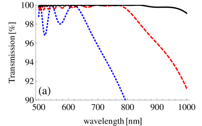
with being the amplitude of the magnetic field induction. We assumed the magnitude of the magnetic field to be T. Simulations were carried out for three different lengths: m, m and m.
The choice of optically active medium (TGG) roughly defines the wavelength range of presented optical isolator. Transmission window of terbium doped fibre (500-1000 nm) and the magnitude of Faraday rotation constitutes the range of operation of isolator simulated in this section. Such isolator would be suitable in experiments with Ti:Sapphire laser (central wavelength at 780 nm). To achieve a similar performance in a different wavelength range requires a different choice of paramagnetic ions, which would induce a Faraday rotation of significant amplitude. For a telecommunication wavelengths bismuth rare-earth ions might be an appropriate choice.
The other issue that must be taken into account is a single-mode performance of fibre. The higher order modes induced in a fibre might negatively affect the performance of isolator. Such fibre must be adjusted to a wavelength window in which the isolator is expected to operate. The commercial manufacturers provide a wide range of such fibres [35].
We quantify the performance of the designed isolator with its transmission and isolation. Transmission indicates the intensity of light passing through the isolator as compared to the intensity at the input. In the forward direction we have
| (11) |
in the backward direction
| (12) |
where represent the Stokes vector of light travelling forwards, — for light travelling backwards, and refer to the input horizontal and output vertical polarizers, respectively. Furthermore, is the intensity of light entering the isolator, whereas and are the intensities measured after the diode in the forward and backward directions.
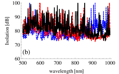
Figure 4 depicts the results of our calculations for the three fibre lengths. In Figure 4 a we presented the intensity of light in the forward direction and in figure 4 b the isolation. One can notice the exceptionally high level of isolation over the whole range of wavelengths considered. What is interesting, the level of isolation is almost constant irrespective of the length of the isolator.
The price we have to pay for broadband isolation is the transmission window decreasing with decreasing length of the isolator. As the length of the setup decreases the adiabatic condition is weakened and, thus, the transmission becomes worse.
The transmission was calculated with an assumption that the fibre is lossless. In practice, the light travelling through a fibre is attenuated. However, because the length of our isolator is relatively short, the losses should be negligible. The isolation of the best commercial broadband fibre diodes [37] is no greater than 32 dB and the range of isolation is around 150 nm. As seen in Figure 4 b, the isolation of our diode remains greater than 70 dB for a range as wide as 500 nm. Because of the robustness of adiabatic techniques, the isolation would be also insensitive to variations in the temperature and the length of the fibre.
6 Conclusions
In this manuscript we proposed a novel design of the fibre optical isolator, which operates over a broad range of wavelengths. The adiabatic evolution has been successfully applied to obtain a robust broadband performance of the optical diode under study. The isolator can be further enhanced by inducing birefringence of higher magnitude. This is possible with stress-induced birefringence, as in our simulations we used a moderate value of the former. To obtain higher circular birefringence with the Faraday effect one can apply stronger magnetic field or use a different magnetoactive medium to assure higher value of the Verdet constant. Increasing the value of birefringence would also result in the decrease of the length of the device.
Acknowledgements
This work is supported by the Bulgarian NSF Grant DMU-03/103.
References
References
- [1] Rayleigh L 1885 Phil. Trans. R. Soc. Lond. 176 343
- [2] Iwamura H, Hayashi S and Iwasaki H 1978 Opt. Quant. Electr. 10 393
- [3] Johnston T F and Proffitt W 1980 IEEE J. Quant. Electr. 16 483
- [4] Schulz P A 1989 Appl. Opt. 28 4458
- [5] Schulz P A Broadband Faraday Isolator U.S. Patent 5,052,786 (1 October 1991).
- [6] Parfenov V A and Parfenov V A 2002 Class. Quantum Grav.19 1865
- [7] Berent M, Rangelov A A and Vitanov N V 2013 J. Opt. Soc. Am.A 30 149
- [8] Levitt M H and Freeman R 1979 J. Magn. Reson. 33 473
- [9] Levitt M H 1986 Prog. Nucl. Magn. Reson. Spectrosc. 18 61
- [10] Torosov B and Vitanov N V 2011 Phys. Rev. A 83 053420
- [11] Rangelov A A, Gaubatz U and Vitanov N V 2010 Opt. Commun. 283 3891
- [12] Darsht M Y, Zeldovich B Y and Kundikova N D 1997 Rus. Phys. J. 40 71
- [13] Swanson E A, Izatt J A, Hee M R, Huang D, Lin C P, Schuman J S, Puliafito C A and Fujimoto J G 1993 Opt. Lett. 18 1864
- [14] Bouma B, Tearney G J, Boppart S A, Hee M R, Brezinski M E and Fujimoto J G 1995 Opt. Lett. 20 1486
- [15] Hee M R, Huang D, Swanson E A and Fujimoto J G 1992 J. Opt. Soc. Am.B 9 903
- [16] Udem T, Holzwarth R and Hänsch T W 2002 Nature 416 233
- [17] MacMaster W H 1961 Rev. Mod. Phys. 33 8
- [18] Schmieder R W 1969 J. Opt. Soc. Am.59 297
- [19] Kubo H and Nagata R 1980 Opt. Commun. 34 306
- [20] Kubo H and Nagata R 1983 J. Opt. Soc. Am.73 1719
- [21] Kubo H and Nagata R 1985 J. Opt. Soc. Am.2 30
- [22] Gaubatz U, Rudecki P, Schiemann S and Bergmann K 1990 J. Chem. Phys. 92 5363
- [23] Bergmann K, Theuer H and Shore B W 1998 Rev. Mod. Phys. 70 1003
- [24] Vitanov N V, Fleischhauer M, Shore B W and Bergmann K 2001 Adv. At. Mol. Opt. Phys. 46 55
- [25] Huang H C 1997 Appl. Opt. 36 6968
- [26] Huang H C 1997 Appl. Opt. 36 4241
- [27] Fernandes L A, Grenier J R, Herman P R, Aitchison J S and Marques P V S 2012 Opt. Express 20 24103
- [28] Cruz J L, Andres M V and Hernandez M A 1996 Appl. Opt. 35 922
- [29] Ballato J and Snitzer E 1995 Appl. Opt. 34 6848
- [30] Sun L 2010 All-fiber Faraday Devices Based on Terbium-doped Fiber (Rochester, New York: University of Rochester)
- [31] Sun L, Jiang S, Zuegel J D and Marciante J R 2010 Opt. Lett. 35 706
- [32] Northrop Grumman Aerospace Systems, http://www.as.northropgrumman.com/products/synoptics_tgg/index.html
- [33] Hayakawa T, Nogami M, Nishi N and Sawanobori N 2002 Chem. Mater. 14 3223
- [34] Villora E G, Molina P, Nakamura M, Shimamura K, Hatanaka T, Funaki A and Naoe K 2011 Appl. Phys. Lett. 99 011111
- [35] ThorLabs Single Mode Fibres, http://www.thorlabs.de/newgrouppage9.cfm?objectgroup_id=949
- [36] Weller L, Kleinbach K S, Zantile M A, Knappe S, Hughes I G and Adams C S 2012 Opt. Lett. 37 3405
- [37] ThorLabs fibre isolators for broadband SLDs, http://thorlabs.com/newgrouppage9.cfm?objectgroup_id=4376