1Department of Biomedical Engineering, College of Engineering, Peking University, Beijing 100871, China;
2 School of Life Sciences and Biotechnology, Shanghai Jiao Tong University, No. 800 Dongchuan Road, Shanghai 200240, China;
3Advanced Cytometry Labs, MQphotonics Research Centre, Macquarie University, NSW 2109, Sydney, Australia;
4Wallace H Coulter Department of Biomedical Engineering, Georgia Institute of Technology and Emory University, Atlanta, USA
*Email:xipeng@pku.edu.cn
To analytically derive the field of circular polarized incident laser, it is necessary to note that in the rotated coordinations, Eq. (1) still holds with phase mask function
for the excitation beam and for the depletion beam. It yields
In Eq. (4) the parameters are defined as
|
|
|
(1) |
where ,, , , , , , , .
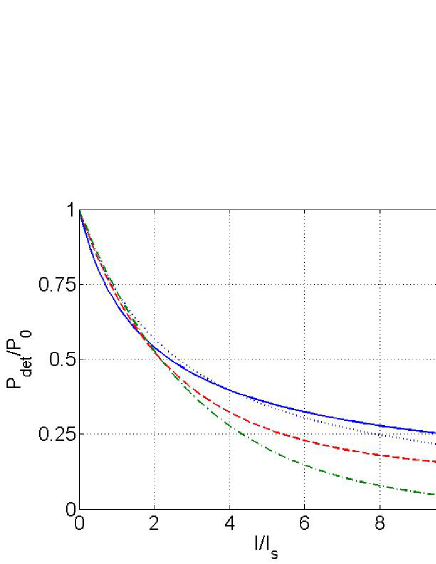
To obtain Eq.(5) it is important to keep in mind that without phase plate . If we defined the depletion power as when peak fluoresce intensity into half, we also has . So depletion later power in Eq.(4) is equivalent to peak intensity ratio in Eq.(5). For continuous wave, , , and yield
|
|
|
(2) |
And for continuous wave, , , and yield
|
|
|
(3) |
Then in Eq.(5) factor and can be obtained.
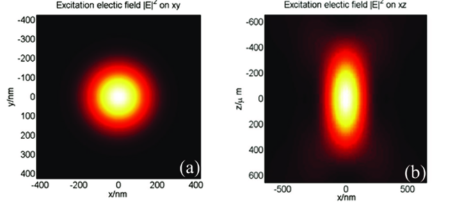
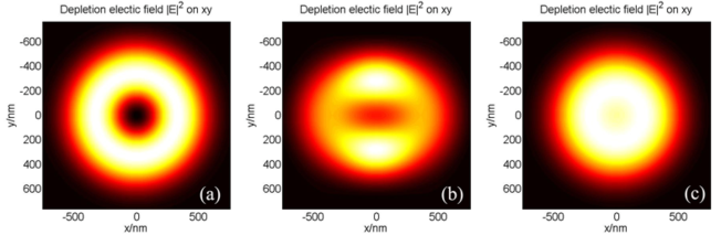
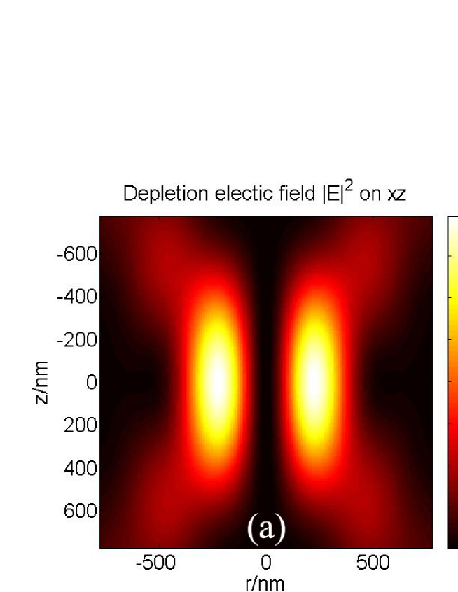
To verify our code STED3D, first we simulated the excitation intensity on xy and xz plane in Fig. S1. The FWHM is 256.8 nm and 605.7 nm respectively, in good agreement with result from PSFlab [19], thus verifying our code. Then we plotted in Fig. S2 the intensity on the xy plane of the focus for the depletion beam with left-circular polarized (a), linear polarized (b), and right-circular polarized laser (c). It confirms our conclusion that only the left-circular polarized depletion beam results in zero intensity in the focus. Also we plotted in Fig. S3 intensity of left-circular polarized depletion beam with Eq. (S2) in (b). The simulated STED distribution in both linear and circular polarization agreed well with the results of [23], and again the matching results verified our derivation.