Bulk magnetoelectricity in the hexagonal manganites and ferrites

Hena Das School of Applied and Engineering Physics, Cornell University, Ithaca, NY, USA    Aleksander L. Wysocki School of Applied and Engineering Physics, Cornell University, Ithaca, NY, USA    Yanan Geng Department of Physics and Astronomy, Rutgers University, Piscataway, NJ, USA    Weida Wu Department of Physics and Astronomy, Rutgers University, Piscataway, NJ, USA    Craig J. Fennie fennie@cornell.edu School of Applied and Engineering Physics, Cornell University, Ithaca, NY, USA
Abstract

Improper ferroelectricity (trimerization) in the hexagonal manganites RMnO3 leads to a network of coupled structural and magnetic vortices that induce domain wall magnetoelectricity and magnetization (M) neither of which, however, occurs in the bulk. Here we combined first-principles calculations, group-theoretic techniques, and microscopic spin models to show how the trimerization not only induces a polarization (P) but also a bulk M and bulk magnetoelectric (ME) effect. This results in the existence of a bulk linear ME vortex structure or a bulk ME coupling such that if P reverses so does M. To measure the predicted ME vortex, we suggest RMnO3 under large magnetic field. We suggest a family of materials, the hexagonal RFeO3 ferrites, also display the predicted phenomena in their ground state.

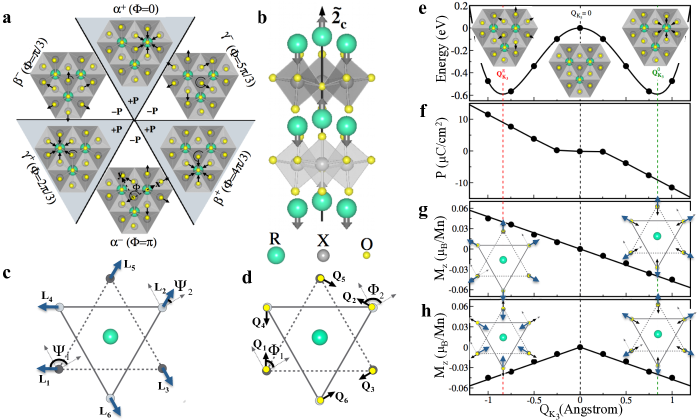
Two themes at the forefront of materials physics are the cross-coupling of distinct types of ferroic order Bousquet et al. (2008); Tokunaga et al. (2009); Lee et al. (2010); Tokunaga et al. (2012) and topological defects in systems with spontaneous broken symmetry Mermin (1979); Balke et al. (2012); Meier et al. (2012); Tagantsev and Sonin (1989). Common to both are a plethora of novel phenomenon to understand, and new properties and functionalities to exploit for novel applications. Multiferroics Ramesh and Spaldin (2007); Cheong and Mostovoy (2007) are an ideal platform to realize both themes in a single material. In this regard, an exciting development is the discovery of a topologically protected vortex-domain structure in one of the most extensively studied class of multiferroics, the hexagonal (hexa) rare-earth manganites. Here, antiphase structural (‘trimer’) domains are clamped to ferroelectric domain walls (and vice versa) Choi et al. (2010); Chae et al. (2010); Mostovoy (2010); Kumagai and Spaldin (2013) forming a ‘clover-leaf’ pattern, Fig. 1a. These trimer domains have a particular phase relationship that result in the appearance of structural vortices, which in turn induce magnetic vortices Geng et al. (2012); Artyukhin et al. (2012), strongly coupled antiferromagnetism and the polarization at the domain wall. This domain wall magnetoelectric phenomenon produces a magnetization localized at the wall Geng et al. (2012); Artyukhin et al. (2012).

The key to realizing these unusual effects is the improper nature of ferroelectricity. Here the polarization (P) which is stable in the paraelectric (PE) P63/mmc structure, is induced by a zone-tripling structural distortion, QK3ΦsuperscriptsubscriptQsubscript𝐾3Φ\textbf{Q}_{K_{3}}^{\Phi} Van Aken et al. (2004); Fennie and Rabe (2005); Artyukhin et al. (2012). The latter, referred to as the trimer distortion, is associated with a 2-up/1-down buckling of the R-planes and tilting of the MnO5 bipyramids, Fig. 1b. It is nonlinearly coupled to the polarization,

trimerPzQK33cos(3Φ)similar-tosubscripttrimersubscript𝑃𝑧superscriptsubscript𝑄subscript𝐾33cos3Φ\mathcal{F}_{\rm trimer}\sim{P_{z}}{Q}_{K_{3}}^{3}{\rm cos}(3\Phi) (1)

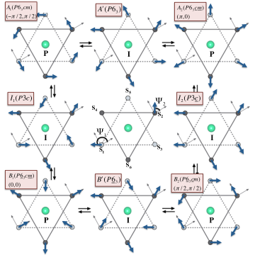
the form of which implies that a nonzero trimer distortion induces a nonzero P. There are three distinct ΦΦ\Phi domains (α𝛼\alpha, β𝛽\beta, and γ𝛾\gamma) corresponding to one of the 3 permutations of 2-up/1-down. Also there are two tilting directions, either towards (+) or away from (-) the 2~csubscript~2𝑐\tilde{2}_{c} axis, i.e., 1-up/2-down or 2-up/1-down, respectively. This results in six P63cm structural domains. A consequence of the improper origin of ferroelectricity is that the sign of P depends on the direction of QK3ΦsuperscriptsubscriptQsubscript𝐾3Φ\textbf{Q}_{K_{3}}^{\Phi}. This simple fact leads to the nontrivial domain structure of the hexa manganites, Fig 1Choi et al. (2010); Artyukhin et al. (2012); Mostovoy (2010); Chae et al. (2010).

Refer to caption
Figure 1: First Principles: Improper structural ferroelectricity inducing weak-ferromagnetism, Mz, in hexagonal structure from first principles. Results are shown for ErMnO3, however, they are true for all hexa manganites and RFeO3 ferrites in the A2 phase that we have considered a, Six structural domains of the primary “trimer” QK3ΦsuperscriptsubscriptQsubscript𝐾3Φ\textbf{Q}_{K_{3}}^{\Phi} distortion and the secondary polarization P. Here α+Φ=0superscript𝛼Φ0\alpha^{+}\Longleftrightarrow\Phi=0 and a counterclockwise rotation corresponds to domains differing by Φ=+π/3Φ𝜋3\Phi=+\pi/3. Arrows indicate the direction of the trimer distortions, only distortions around the 2~csubscript~2𝑐\tilde{2}_{c} axis are shown for clarity. b, crystal structure of the ferroelectric phase (QK30superscriptsubscript𝑄subscript𝐾30Q_{K_{3}}^{0} (α+superscript𝛼\alpha^{+}) domain). c, The spin angles Ψ1subscriptΨ1\Psi_{1} and Ψ2subscriptΨ2\Psi_{2} describing all possible 120 non-collinear antiferromagnetic (AFM) spin configurations (see Supplemental). LisubscriptL𝑖\textbf{L}_{i} (i𝑖absenti\in 1 to 6) denotes transverse component of the ithsuperscript𝑖𝑡i^{th} spin. We define L1=cosΨ1x^+sinΨ1y^subscriptL1subscriptΨ1^𝑥subscriptΨ1^𝑦\textbf{L}_{1}=\cos\Psi_{1}\hat{x}+\sin\Psi_{1}\hat{y}, L2=cosΨ2x^+sinΨ2y^subscriptL2subscriptΨ2^𝑥subscriptΨ2^𝑦\textbf{L}_{2}=\cos\Psi_{2}\hat{x}+\sin\Psi_{2}\hat{y} and remaining four vectors can be created by the crystal symmetry operations. d, Represents directions of local trimer distortions. The local trimer distortion at site 1 (Q1subscriptQ1\textbf{Q}_{1}) and 2 (Q2subscriptQ2\textbf{Q}_{2}) are defined as, Q1=cosΦ1x^+sinΦ1y^subscriptQ1subscriptΦ1^𝑥subscriptΦ1^𝑦\textbf{Q}_{1}=\cos\Phi_{1}\hat{x}+\sin\Phi_{1}\hat{y} and Q2=cosΦ2x^+sinΦ2y^subscriptQ2subscriptΦ2^𝑥subscriptΦ2^𝑦\textbf{Q}_{2}=\cos\Phi_{2}\hat{x}+\sin\Phi_{2}\hat{y}, respectively. Crystal symmetry implies Φ1ΦsubscriptΦ1Φ\Phi_{1}\equiv\Phi and Φ2=πΦ1subscriptΦ2𝜋subscriptΦ1\Phi_{2}=\pi-\Phi_{1}. e, Energy, f, P, g and h, Mz as a function of QK3subscript𝑄subscript𝐾3Q_{K_{3}}, allowing only Φ=0Φ0\Phi=0 or π𝜋\pi trimer domains. Notice that P =0 when QK3ΦsuperscriptsubscriptQsubscript𝐾3Φ\textbf{Q}_{K_{3}}^{\Phi} = 0, suggesting that a proper ferroelectric mechanism in not likely. Note that for higher magnitude of QK3subscriptQsubscript𝐾3\textbf{Q}_{K_{3}}, PQK3proportional-to𝑃subscript𝑄subscript𝐾3P\propto Q_{K_{3}} and MzQK3proportional-tosubscript𝑀𝑧subscript𝑄subscript𝐾3M_{z}\propto Q_{K_{3}}, thus provide linear ME coupling.

Our focus here is on elucidating a remarkable interplay of this trimerization, magnetism, and polarization in the hexa manganite structure. We show from first principles that the trimer structural distortion not only induces a P, but can also induce both a bulk magnetization, M, and a bulk linear ME effect. We make this clear by connecting an exact microscopic theory of spin-lattice coupling to a simple phenomenological theory. This not only brings additional insight to known experiments, but leads us to discover entirely new bulk phenomena, not previously seen in a multiferroic such as 1) the existence of a linear magnetoelectric (ME) vortex structure and 2) a bulk coupling of ferroelectric (FE) and ferromagnetic domains such that if P reverses 180 so does M.

We show that the former is widely accessible in most hexa RMnO3 manganites under large magnetic fields, while the latter is realizable in the ground state of a new family of materials, the hexa RFeO3 ferrites. Recently thin films of RFeO3 have been epitaxially stabilized in the hexa P63cm structure Bossak et al. (2004); Magome et al. (2010); Wang et al. (2013). By performing a detail comparison of the ferrites to the manganites we explain why the ground state of all ferrites display an intrinsic, bulk M and bulk linear ME effect.

I First-principles calculations on switching ΦΦ\Phi by 180

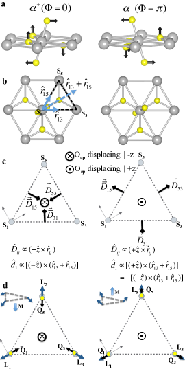
Geometric frustration of the strongly antiferromagnetic (AFM) nearest neighbor Mn (or Fe) spins leads to a planar 120 non-collinear order which can be described by two free parameters, Ψ1subscriptΨ1\Psi_{1} and Ψ2subscriptΨ2\Psi_{2}, as shown in Fig. 1c. Four principle configurations, denoted A1 (π/2,π/2𝜋2𝜋2-\pi/2,\pi/2), A2 (π,0𝜋0\pi,0), B1 (0,0000,0) and B2 (π/2,π/2𝜋2𝜋2\pi/2,\pi/2), have been previously defined, among which it is well-known that only the A2 (magnetic space group P63cm) and intermediate spin configurations that contain a component of A2 allow a net M along the z𝑧z axis. What hasn’t been appreciated in the past is that this known symmetry-allowed M is in fact induced by the trimer distortion, the consequences of which are quite profound.

We now begin to make this clear by performing first-principles calculations for a specific example, ErMnO3 in the A2 phase (which is the spin configuration realized experimentally under an applied magnetic field Fiebig et al. (2003)). In first-principles calculations of the hexagonal manganite structure it is easy to reverse the trimer distortion, and hence P, via a structural change from a 1-up/2-down buckling and tilting ‘in’ of the R-planes and MnO5 bipyramids, respectively, to a 2-up/1-down and tilting ‘out’, thus remaining in the same distinct domain, e.g., α+αsuperscript𝛼superscript𝛼\alpha^{+}\rightarrow\alpha^{-}.

Having performed these calculations we find that the trimer distortion not only induces ferroelectricity, but also weak-ferromagetism Dzyaloshinskii (1957); Moriya (1960) and the linear ME effect, αzz=Mz/EzQMzQPzsubscript𝛼𝑧𝑧subscript𝑀𝑧subscript𝐸𝑧subscript𝑄subscript𝑀𝑧subscript𝑄subscript𝑃𝑧\alpha_{zz}=\partial M_{z}/\partial E_{z}\approx\partial_{Q}M_{z}*\partial_{Q}P_{z} (see Supplemental), as shown in Figures 1e through 1h. Furthermore, notice that reversal of the trimer distortion reverses either the direction of the M, Fig. 1g, or the sign of the linear ME tensor, Fig. 1h, where both situations are symmetry equivalent and correspond to whether or not the AFM spin configuration remains fixed, respectively. This result is true for all hexa manganites and RFeO3 ferrites in the A2 phase that we have considered and as we prove below is a general property of the A2-phase.

We pause now to stress the point that real switching will occur via a rotation to a neighboring trimer domainArtyukhin et al. (2012), e.g., α+βsuperscript𝛼superscript𝛽\alpha^{+}\rightarrow\beta^{-} or γsuperscript𝛾\gamma^{-}. These first-principles results, however, contain all of the unique ME physics, that is, if the polarization is reversed either the bulk magnetization will reverse or the antiferromagnetic order will change in such a way that the sign of the bulk magnetoelectric tensor changes sign. To understand the consequences of these two choices we next derive a simple phenomenological theory – valid for any trimer domain, ΦΦ\Phi, and any spin configuration – starting from a microscopic model.

II Phenomenology theory from microscopic model: Generalizing the first-principles results to switching ΦΦ\Phi by nπ3𝑛𝜋3n{\pi\over 3}

We start by deriving a spin-lattice model from an effective spin Hamiltonian Solovyev et al. (2012)

H=ijJij𝐒i𝐒j+ij𝐃ij𝐒j×𝐒j+i𝐒iτ^i𝐒i𝐻subscript𝑖𝑗subscript𝐽𝑖𝑗subscript𝐒𝑖subscript𝐒𝑗subscript𝑖𝑗subscript𝐃𝑖𝑗subscript𝐒𝑗subscript𝐒𝑗subscript𝑖subscript𝐒𝑖subscript^𝜏𝑖subscript𝐒𝑖H=\sum_{ij}J_{ij}\mathbf{S}_{i}\cdot\mathbf{S}_{j}+\sum_{ij}\mathbf{D}_{ij}\cdot\mathbf{S}_{j}\times\mathbf{S}_{j}+\sum_{i}\mathbf{S}_{i}\cdot\mathbf{\hat{\tau}}_{i}\cdot\mathbf{S}_{i} (2)

where the Jijsubscript𝐽𝑖𝑗J_{ij}’s are the symmetric exchange interactions and 𝐃ijsubscript𝐃𝑖𝑗\mathbf{D}_{ij}’s are the Dzyaloshinskii-Moriya (DM) antisymmetric exchange vectors, and τ^isubscript^𝜏𝑖\mathbf{\hat{\tau}}_{i} is the single-ion anisotropy (SIA) tensor. (Note that our calculations reveal that a dominant DM interaction, DijsubscriptD𝑖𝑗\textbf{D}_{ij}, exists only between nearest neighbor spins within the triangular planes.)

In the PE structure the DM vector has only a z𝑧z component, which further acts to confine the spins within the xy𝑥𝑦xy plane, while the SIA tensor is diagonal. In the FE structure, however, the trimer distortion induces a transverse component of the DM vector, DijxysubscriptsuperscriptD𝑥𝑦𝑖𝑗\textbf{D}^{xy}_{ij}, parallel to the xy𝑥𝑦xy plane and off-diagonal components of the SIA tensor. These induced interactions are key and therefore are the focus in the remaining discussion (all other interactions can be safely ignored).

The effective DM and SIA interactions for a single layer of spins. Let us first consider a single layer of spins, denoted as layer I. We derive the relationship between the local structural distortions and the induced DM and SIA interactions by considering a single triangle of spins (S1subscriptS1\textbf{S}_{1}, S3subscriptS3\textbf{S}_{3} and S5subscriptS5\textbf{S}_{5}), in the α+superscript𝛼\alpha^{+} and αsuperscript𝛼\alpha^{-} domains, Fig. S3c (the exact mapping from a single layer of spins to a single triangle is proved in the Supplemental).

Note that the induced DM and SIA interactions cant the spins out of the plane, but all spins in a single plane have to cant in the same direction, we can therefore write Si=Li+MIsubscriptS𝑖subscriptL𝑖subscriptMI\textbf{S}_{i}=\textbf{L}_{i}+\textbf{M}_{\rm I}, where LiSixysubscriptL𝑖superscriptsubscriptS𝑖𝑥𝑦\textbf{L}_{i}\equiv\textbf{S}_{i}^{xy}, i.e., the component of the spin lying in the xy𝑥𝑦xy plane (Fig. 1c), while MISizsubscriptMIsuperscriptsubscriptS𝑖𝑧\textbf{M}_{\rm I}\equiv\textbf{S}_{i}^{z} is the net magnetic moment per spin of layer I. The total canting energy per spin can be written as

EIcanting=EIDM+EISIA=13i=1,3,5𝐝ieff[𝐋i×𝐌I].superscriptsubscript𝐸Icantingsuperscriptsubscript𝐸IDMsuperscriptsubscript𝐸ISIA13subscript𝑖135subscriptsuperscript𝐝eff𝑖delimited-[]subscript𝐋𝑖subscript𝐌IE_{\rm I}^{\rm canting}=E_{\rm I}^{\rm DM}+E_{\rm I}^{\rm SIA}=\frac{1}{3}\sum_{i=1,3,5}\mathbf{d}^{\rm eff}_{i}\cdot[\mathbf{L}_{i}\times\mathbf{M}_{\rm I}]. (3)

where 𝐝ieff=𝐝iDM+𝐝iSIAsubscriptsuperscript𝐝eff𝑖superscriptsubscript𝐝𝑖DMsuperscriptsubscript𝐝𝑖SIA\mathbf{d}^{\rm eff}_{i}=\mathbf{d}_{i}^{\rm DM}+\mathbf{d}_{i}^{\rm SIA} is the effective DM-like vector induced by the tilting of the bipyrimid. This effective interaction includes contributions from both the transverse DM interactions and the off-diagonal elements of SIA tensor (see Supplemental for derivation). Considering that MI=MIzz^subscriptMIsuperscriptsubscript𝑀I𝑧^𝑧\textbf{M}_{\rm I}=M_{\rm I}^{z}\hat{z} and MIz𝐝ieff[𝐋i×z^]=MIz𝐋i[z^×𝐝ieff]superscriptsubscript𝑀I𝑧subscriptsuperscript𝐝eff𝑖delimited-[]subscript𝐋𝑖^𝑧superscriptsubscript𝑀I𝑧subscript𝐋𝑖delimited-[]^𝑧subscriptsuperscript𝐝eff𝑖M_{\rm I}^{z}\mathbf{d}^{\rm eff}_{i}\cdot[\mathbf{L}_{i}\times\hat{z}]=M_{\rm I}^{z}\mathbf{L}_{i}\cdot\left[{\hat{z}}\times\mathbf{d}^{\rm eff}_{i}\right], the canting energy per spin can be compactly rewritten as

EIcanting=13|𝐝|MIzi=1,3,5LiQ^i=|𝐝|MIz(LIQ^I)superscriptsubscript𝐸Icanting13𝐝superscriptsubscript𝑀I𝑧subscript𝑖135subscriptL𝑖subscript^Q𝑖𝐝superscriptsubscript𝑀I𝑧subscriptLIsubscript^QIE_{\rm I}^{\rm canting}=\frac{1}{3}|\mathbf{d}|M_{\rm I}^{z}\sum_{i=1,3,5}\textbf{L}_{i}\cdot\hat{\textbf{Q}}_{i}=|\mathbf{d}|M_{\rm I}^{z}(\textbf{L}_{\rm I}\cdot\hat{\textbf{Q}}_{\rm I}) (4)

where we have defined Q^isubscript^Q𝑖\hat{\textbf{Q}}_{i} such that |𝐝ieff|Q^iz^×𝐝ieffsubscriptsuperscript𝐝eff𝑖subscript^Q𝑖^𝑧subscriptsuperscript𝐝eff𝑖|\mathbf{d}^{\rm eff}_{i}|\hat{\textbf{Q}}_{i}\equiv\hat{z}\times\mathbf{d}^{\rm eff}_{i}, and where by symmetry |𝐝ieff|=|𝐝eff||𝐝|subscriptsuperscript𝐝eff𝑖superscript𝐝eff𝐝|\mathbf{d}^{\rm eff}_{i}|=|\mathbf{d}^{\rm eff}|\equiv|\mathbf{d}| and L1Q^1=L2Q^2=L3Q^3LIQ^IsubscriptL1subscript^Q1subscriptL2subscript^Q2subscriptL3subscript^Q3subscriptLIsubscript^QI\textbf{L}_{1}\cdot\hat{\textbf{Q}}_{1}=\textbf{L}_{2}\cdot\hat{\textbf{Q}}_{2}=\textbf{L}_{3}\cdot\hat{\textbf{Q}}_{3}\equiv\textbf{L}_{\rm I}\cdot\hat{\textbf{Q}}_{\rm I}.

It is interesting that 𝐐^isubscript^𝐐𝑖\mathbf{\hat{Q}}_{i} is the direction of the in-plane displacement of the apical oxygen that lies directly above spin 𝐒isubscript𝐒𝑖\mathbf{S}_{i}. It is zero in the PE phase and is in opposite directions in the α±superscript𝛼plus-or-minus\alpha^{\pm} domains. It behaves in every aspect as an order parameter that defines the local trimer distortion. In fact, one of the 𝐐^isubscript^𝐐𝑖\mathbf{\hat{Q}}_{i}’s is the atomic distortion that Mostovoy has used to define a particular trimer domain Artyukhin et al. (2012). If we had considered a different domain, e.g., β+superscript𝛽\beta^{+}, the 𝐐^isubscript^𝐐𝑖\mathbf{\hat{Q}}_{i}’s rotate appropriately and in fact have similar transformational properties as the trimer structural distortions, 𝐐K3Φsubscriptsuperscript𝐐Φsubscript𝐾3\mathbf{Q}^{\Phi}_{K_{3}}. This suggests (and we prove in the Supplemental) that 𝐐^isubscript^𝐐𝑖\mathbf{\hat{Q}}_{i} is a local trimer distortion, which induces the local DM-like interaction, 𝐝ieffsuperscriptsubscript𝐝𝑖eff\mathbf{d}_{i}^{\rm eff}, and subsequently cants the spins.

It is now clear that 1) if the relative phase between the local AFM spin, LIsubscriptLI\textbf{L}_{\rm I}, and the local trimer distortion, 𝐐^Isubscript^𝐐I\mathbf{\hat{Q}}_{\rm I}, changes sign, the net magnetic moment per spin of a layer, 𝐌Isubscript𝐌I\mathbf{M}_{\rm I}, reverses, i.e, 𝐌I(𝐋I𝐐^I)z^proportional-tosubscript𝐌Isubscript𝐋Isubscript^𝐐I^𝑧\mathbf{M}_{\rm I}\propto(\mathbf{L}_{\rm I}\cdot\mathbf{\hat{Q}}_{\rm I}){\hat{z}}, and 2) canting occurs only in a FE phase (where 𝐐^I0subscript^𝐐I0\mathbf{\hat{Q}}_{\rm I}\neq 0) and only when there is a nonzero projection of a spin along the direction of the local trimer distortion. This is why there is no canting for the A1 and B2 spin states (where 𝐋I𝐐I=0subscript𝐋Isubscript𝐐I0\mathbf{L}_{\rm I}\cdot\mathbf{Q}_{\rm I}=0).

The real structure – the stacking of two layers. The real hexa unit cell has two triangular planes, layer I (which includes sites 1, 3, 5) and layer II (which includes sites 2, 4, 6), stacked along the z𝑧z axis, as shown in Fig. 1c and d. The canting energy per spin is

Ecanting=|𝐝|[MIz(LI𝐐^I)+MIIz(𝐋II𝐐^II)]subscript𝐸canting𝐝delimited-[]subscriptsuperscript𝑀𝑧IsubscriptLIsubscript^𝐐Isubscriptsuperscript𝑀𝑧IIsubscript𝐋IIsubscript^𝐐IIE_{\rm canting}=|\mathbf{d}|\left[M^{z}_{\rm I}(\textbf{L}_{\rm I}\cdot\mathbf{\hat{Q}}_{\rm I})+M^{z}_{\rm II}(\mathbf{L}_{\rm II}\cdot\mathbf{\hat{Q}}_{\rm II})\right] (5)

This can be alternatively written as

Ecantingsubscript𝐸canting\displaystyle E_{\rm canting} =\displaystyle= |𝐝|Mz[LI𝐐^I+𝐋II𝐐^II]𝐝subscript𝑀𝑧delimited-[]subscriptLIsubscript^𝐐Isubscript𝐋IIsubscript^𝐐II\displaystyle|\mathbf{d}|M_{z}[\textbf{L}_{\rm I}\cdot\mathbf{\hat{Q}}_{\rm I}+\mathbf{L}_{\rm II}\cdot\mathbf{\hat{Q}}_{\rm II}] (6)
+|𝐝|Lz[LI𝐐^I𝐋II𝐐^II]𝐝subscript𝐿𝑧delimited-[]subscriptLIsubscript^𝐐Isubscript𝐋IIsubscript^𝐐II\displaystyle+|\mathbf{d}|L_{z}[\textbf{L}_{\rm I}\cdot\mathbf{\hat{Q}}_{\rm I}-\mathbf{L}_{\rm II}\cdot\mathbf{\hat{Q}}_{\rm II}]

where Mz(MIz+MIIz)/2subscript𝑀𝑧superscriptsubscript𝑀I𝑧superscriptsubscript𝑀II𝑧2M_{z}\equiv(M_{\rm I}^{z}+M_{\rm II}^{z})/2 and Lz(MIzMIIz)/2subscript𝐿𝑧superscriptsubscript𝑀I𝑧superscriptsubscript𝑀II𝑧2L_{z}\equiv(M_{\rm I}^{z}-M_{\rm II}^{z})/2 are the total and stagger magnetic moment per spin respectively. Although the specific sites we choose to define I and II are arbitrary, it is convenient to associate I with site 1 and II with site 2. Because symmetry implies Φ1=πΦ2subscriptΦ1𝜋subscriptΦ2\Phi_{1}=\pi-\Phi_{2}, where Φ1subscriptΦ1\Phi_{1} (Φ2subscriptΦ2\Phi_{2}) is the local trimer angle at site 1 (2), a single trimer angle, ΦΦ1ΦsubscriptΦ1\Phi\equiv\Phi_{1}, can be defined. This single angle was used to define the trimer domains in Fig. 1a.

Note that Eq. 6 is the exact result we derived from Landau theory (see Supplemental) and explains our first-principles calculations displayed in Fig. 1; in the A2 state LI𝐐^IsubscriptLIsubscript^𝐐I\textbf{L}_{\rm I}\cdot\mathbf{\hat{Q}}_{\rm I} = +LII𝐐^IIsubscriptLIIsubscript^𝐐II\textbf{L}_{\rm II}\cdot\mathbf{\hat{Q}}_{\rm II}, and therefore MIz=MIIzsubscriptsuperscript𝑀𝑧Isubscriptsuperscript𝑀𝑧IIM^{z}_{\rm I}=M^{z}_{\rm II} leading to a net magnetization as we previously showed from first principles. For completeness note that in the B1 state, however, the projection has the opposite sign in adjacent layers, LI𝐐^IsubscriptLIsubscript^𝐐I\textbf{L}_{\rm I}\cdot\mathbf{\hat{Q}}_{\rm I} = -LII𝐐^IIsubscriptLIIsubscript^𝐐II\textbf{L}_{\rm II}\cdot\mathbf{\hat{Q}}_{\rm II}. The spins in each plane still cant but since the projection changes sign in adjacent layers no net magnetization exists, MIz=MIIzsubscriptsuperscript𝑀𝑧Isubscriptsuperscript𝑀𝑧IIM^{z}_{\rm I}=-M^{z}_{\rm II}. We call this weak-antiferromagentism, wAFM.

III Implications: testable predictions

Note that if P switched via rotating ΦΦ\Phi by π/3𝜋3\pi/3, e.g., α+βsuperscript𝛼superscript𝛽\alpha^{+}\rightarrow\beta^{-}, L must rotate by either |π/3|𝜋3|\pi/3| (L𝐐^α+=1L𝐐^β=1Lsubscript^𝐐superscript𝛼1Lsubscript^𝐐superscript𝛽1\textbf{L}\cdot\mathbf{\hat{Q}}_{\alpha^{+}}=-1\rightarrow\textbf{L}\cdot\mathbf{\hat{Q}}_{\beta^{-}}=-1) or |2π/3|2𝜋3|2\pi/3| (L𝐐^α+=1L𝐐^β=+1Lsubscript^𝐐superscript𝛼1Lsubscript^𝐐superscript𝛽1\textbf{L}\cdot\mathbf{\hat{Q}}_{\alpha^{+}}=-1\rightarrow\textbf{L}\cdot\mathbf{\hat{Q}}_{\beta^{-}}=+1). s

Refer to caption
Figure 2: Predicted clamping of trimer and magnetic domains and electric field response. At the lowest energy trimer domain wall ΦΦ\Phi changes by π/3𝜋3\pi/3, which will rotate the AFM spin vectors, L1subscriptL1\textbf{L}_{1} and L2subscriptL2\textbf{L}_{2}, by either a, π/3𝜋3\pi/3 and π/3𝜋3-\pi/3 or b, 2π/32𝜋3-2\pi/3 and 2π/32𝜋32\pi/3. In the former case Mz remains constant while in the latter Mz reverses at each trimer domain wall, i.e., ferroelectric, ferromagnetic, and trimer domains are mutually clamped. c, The schematic diagram displaying the electric-field switching of ferromagnetic domains (note, figure inspired by Ref.Choi et al. (2010)).

Prediction 1– In the former case the expected domain configurations, Fig. 2a, are such that at trimer domain walls differing by ΔΦ=π/3ΔΦ𝜋3\Delta\Phi=\pi/3 the AFM spins rotate ΔΨ1,2=|π/3|ΔsubscriptΨ12𝜋3\Delta\Psi_{1,2}=|\pi/3|. In this case the direction of the magnetization remains the same across the domain wall, i.e., although P switches, M is not reversed similar to that shown in Fig 1h. Still, there exist a bulk linear ME effect

αzzcos(3Φ)(LI𝐐^I+LII𝐐^II)proportional-tosubscript𝛼𝑧𝑧cos3ΦsubscriptLIsubscript^𝐐IsubscriptLIIsubscript^𝐐II\alpha_{zz}\propto{\rm cos}(3\Phi)\,(\textbf{L}_{\rm I}\cdot\mathbf{\hat{Q}}_{\rm I}+\textbf{L}_{\rm II}\cdot\mathbf{\hat{Q}}_{\rm II}) (7)

(see Supplemental), which in this case leads to a presence of a remarkable linear ME vortex structure as the projections, Li𝐐^isubscriptLisubscript^𝐐i\textbf{L}_{\rm i}\cdot\mathbf{\hat{Q}}_{\rm i}, are equal in all domains, and therefore αzzsubscript𝛼𝑧𝑧\alpha_{zz} is of opposite sign in neighboring trimer domains.

Prediction 2– Note that this seemingly lower energy AFM switching pathway results in a homogeneous magnetization across the entire material. In zero field, this has to be unstable towards the formation of ferromagnetic domains. But what kind of domains? They can occur within the bulk of a trimer domain, i.e., a free AFM domain. There is, however, an energy cost to form this domain wall. An alternative path to minimize the total energy of the system is considered in Fig. 2b, where at trimer domain walls that differ by ΔΦ=π/3ΔΦ𝜋3\Delta\Phi=\pi/3 the AFM spins now rotate ΔΨ1,2=|2π/3|ΔsubscriptΨ122𝜋3\Delta\Psi_{1,2}=|2\pi/3|. In this case, the magnetization direction reverses with the polarization similar to that shown in Fig 1g. Therefore, even though this domain configuration at first appears less likely than Fig 2a, it provides an avenue for the system to minimize the magnetostatic energy without having to introduce free domains. Additionally, in Fig. 2c we sketch the expected response of the domains to electric-field poling. In this process the positive electric field, 𝐄𝐄\mathbf{E}, e.g., chooses the (+𝐏𝐏+\mathbf{P},+𝐌𝐌+\mathbf{M}) state and therefore reversing of the direction of electric field will not only switches the direction of polarization, but also reverses the direction of magnetization.

IV Discussion: possible realizations of predictions

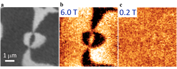
Realization 1: The hexagonal Manganites . In the hexagonal manganites, e.g., ErMnO3, an A2 phase appears under the application of external magnetic field Fiebig et al. (2003). Here, as the magnetic field is swept from zero to a large (for example) positive value, a ME vortex structure is expected to appear. Additionally, as the magnetic field is scanned to negative values the sign of the ME vortex structure should switch. This is precisely what our preliminary imaging of the ME vortex structure shows using a new technique called Magnetoelectric Force Microscopy, as shown in the supplemental.

Realization 2: The A2 ground state in hexa-RFeO3. Are there materials in which this physics is realized in the ground state? Recently thin films of RFeO3 have been epitaxially stabilized in the hexa P63cm structure Bossak et al. (2004); Magome et al. (2010). These hexa ferrites exhibit ferroelectricity above room temperature, but with conflicting results as to its origin Jeong et al. (2012a, b). Additionally there is evidence of a magnetic transition around similar-to\sim 100K, at which M becomes nonzero Jeong et al. (2012a, b); Akbashev et al. (2011); Wang et al. (2013), however, the significance of this or even if it is an intrinsic or bulk effect is not previously known.

Our calculations suggest strongly that ferroelectricity in the hexa ferrites is of the improper structural type where the trimer distortion induces P (see Supplemental for full discussion), and therefore a similar topological domain structure should exist as in the manganites. The difference in electronic structure between manganites and ferrites, however, requires Fe spins of any hexa ferrite to order in the A2 spin configuration in ground state. Additionally, the much stronger exchange interactions leads to the possibility of spin ordering above room temperature, as recently suggested by the experiments of Ref. Wang et al., 2013.) Therefore, both scenarios displayed in Fig. 2 are possible. We now discuss our first-principles calculations indicating that the ground state of any hexagonal ferrite will indeed have the A2 magnetic configuration.

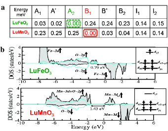
Magnetic structure. In addition to the principle magnetic configurations we also considered the four known intermediate magnetic structures (see Fig.S7). The results of our total energy calculations for LuFeO3, LFO, and LuMnO3, LMO, are presented in Fig. 3a (for clarity we limit our discussion to these two compounds). In agreement with non-linear optical measurements Fiebig et al. (2000), we find that LMO stabilizes in the wAFM B1 state. In contrast, LFO stabilizes in the wFM A2 state giving rise to a net canted spin moment Mz=subscript𝑀𝑧absentM_{z}= 0.02μBsubscript𝜇𝐵\mu_{B}/Fe along the z𝑧z axis. Note, however, that the A1 state, where the net magnetic moment is equal to zero in each layer by symmetry, is also close in energy.

Electronic structure. In the PE phase the crystal field at the TM site has a D3h trigonal point symmetry, which splits atomic 3d𝑑d levels into three sets of states as shown in the insets of Fig.3b. The density of states (DOS) plots calculated for LFO and LMO in the FE phase are shown in Fig. 3b. LFO is a charge-transfer insulator with the conduction band formed by minority Fe 3d𝑑d states and the valence band composed of O 2p𝑝p states, below which are the filled majority Fe 3d𝑑d bands. In the case of LMO majority 3d𝑑d bands are partially filled with d4superscript𝑑4d^{4} electronic configure, while minority 3d𝑑d levels are completely empty. The importance of these differences will be made clear when discussing the magnetic interactions.

Refer to caption
Figure 3: The noncollinear magnetic and electronic structure from first principles. First-principles calculations of a, Noncollinear magnetic energies and b, density of states (collinear). Note that the difference in orbital occupancy is the fundamental reason why ferrites, top, and manganites, bottom, have different magnetic ground states and subsequently the key to the predicted bulk coupling of polarization and magnetism in ferrites. Insets: crystal field splitting and occupancy of the TM majority 3d3𝑑3d channel.

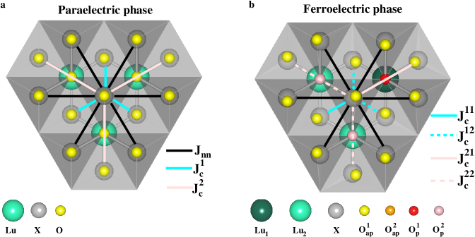
Symmetric exchange. Although it is the DM interactions and SIA that drives spin canting, it is the symmetric exchange that determines the magnetic configuration type. There are two important symmetric exchange interactions. The first is a strong, AFM superexchange interaction between in-plane nn spins, Jnnsubscript𝐽𝑛𝑛J_{nn}. Its magnitude is much larger for LFO compared with LMO, suggesting a substantially larger magnetic ordering temperature for ferrites (within mean field theory the calculated Currie-Weiss temperature for LFO in the FE phase is ΘCW=1525subscriptΘ𝐶𝑊1525\Theta_{CW}=1525 K, while in LMO ΘCW=274subscriptΘ𝐶𝑊274\Theta_{CW}=274com ).

The second is a weak, super-superexchange interaction, Jcsubscript𝐽𝑐J_{c}, which couples consecutive spin planes via a TM-O-Lu-O-TM exchange pathway (see Fig.S8a). In the PE structure, a spin in one layer is connected to three spins in a consecutive layer. Each of these degenerate spin-spin interactions has two equivalent exchange pathways. We find that the interlayer exchange is AFM for LFO but FM for LMO. Although the strength of this interaction is relatively weak, this sign difference turns out to be key.

In the PE structure symmetry implies that the relative orientation of the spins in consecutive spin planes is arbitrary. The trimer distortion, however, splits the three degenerate interactions into: a single Jc11superscriptsubscript𝐽𝑐11J_{c}^{11} interaction, mediated by two equivalent TM-O-Lu1-O-TM exchange pathways, and two Jc12superscriptsubscript𝐽𝑐12J_{c}^{12} interactions, where each interaction is mediated by a TM-O-Lu1-O-TM and a TM-O-Lu2-O-TM exchange pathway (see Fig.S8b). This remarkably introduces an extra contribution to the energy

EinterSE=2ΔJccos(Ψ1Ψ2)superscriptsubscript𝐸interSE2Δsubscript𝐽𝑐subscriptΨ1subscriptΨ2E_{\rm inter}^{\rm SE}=2\Delta J_{c}\cos(\Psi_{1}-\Psi_{2}) (8)

where ΔJc=Jc11Jc12Δsubscript𝐽𝑐superscriptsubscript𝐽𝑐11superscriptsubscript𝐽𝑐12\Delta J_{c}=J_{c}^{11}-J_{c}^{12}, the sign of which is key in determining the spin configuration type: A-type (Ψ2subscriptΨ2\Psi_{2}=Ψ1subscriptΨ1\Psi_{1}+π𝜋\pi) for ΔJc>0Δsubscript𝐽𝑐0\Delta J_{c}>0 or B-type (Ψ2subscriptΨ2\Psi_{2}=Ψ1subscriptΨ1\Psi_{1}) for ΔJc<0Δsubscript𝐽𝑐0\Delta J_{c}<0.

A simple structural analysis shows that the super-super exchange mediated through the Lu2 ion is always weaker than that mediated through the Lu1 ion, and indeed our calculations show that the magnitude of Jc11superscriptsubscript𝐽𝑐11J_{c}^{11} is always larger than Jc12subscriptsuperscript𝐽12𝑐J^{12}_{c} (see Supplemental). We therefore see that the choice between A-type and B-type in the FE structure is in fact determined by the sign of Jcsubscript𝐽𝑐J_{c} in the PE structure. This is important. In ferrites, the AFM nature of the interlayer exchange is uniquely determined by the orbital occupancy, it is always AFM and therefore ferrites will always prefer A𝐴A-type magnetic configurations and the wFM ground state. (Although the interlayer exchange in LMO is FM, which explains why it prefers B𝐵B-type magnetic configurations, it is not universally so; a discussion is given in the Supplement).

V Summary

In this paper we have discussed an intriguing consequence of improper ferroelectricity in the hexagonal manganite-like systems. We have shown for the first time that a non-polar trimer structural distortion not only induces an electrical polarization but also induces bulk weak-ferromagnetism and a bulk linear magnetoelectric vortex structure. It is a universal feature of A2-type hexa systems in which the trimer distortion mediates an intrinsic bulk trilinear-coupling of the polarization, magnetization, and antiferromagnetic order.

Note that it was recently inferred from neutron diffraction Wang et al. (2013) that LFO orders above room temperature (high for a frustrated magnet) in an AFM state with M=0M0\textbf{M}=0, and at a lower temperature undergoes a reorientation transition to the A phase inducing a M0M0\textbf{M}\neq 0. As shown in Fig. 3a, the A1 (M=0M0\textbf{M}=0 by symmetry) and A (finite M allowed) states, lie energetically very close to ground state in LFO, which support such a picture.

There is, however, an intriguing alternative scenario involving a crossover from a state in which several magnetic order types are degenerate to the A2 spin configuration ground state, driven by the trimer distortion. Note that the symmetry of the PE structure not only implies that the A and B spin configurations are degenerate, but in fact that all of the principle spin configurations are degenerate as there can be no in plane anisotropy. The trimer distortion lifts the degeneracy between the A and B spin configurations as

ΔJcQK32proportional-toΔsubscript𝐽𝑐superscriptsubscript𝑄subscript𝐾32\Delta J_{c}\propto Q_{K_{3}}^{2} (9)

while the in plane anisotropy due to the effective DM-like interaction (the trimer distortion induced in plane anisotropy of the SIA tensor is negligible) always favors phases with canted spins and is lifted as

𝐝effQK3proportional-tosuperscript𝐝effsubscript𝑄subscript𝐾3\mathbf{d}^{\rm eff}\propto Q_{K_{3}} (10)

as we show in the Supplemental. In this picture, as temperature is lowered and the trimer distortion increases in magnitude, there is a smooth crossover to the A2 state.

VI Method

The first principles calculations were performed using the DFT+U method Anisimov et al. (1997) with the PBE form of exchange correlation functional Perdew et al. (1996). We considered Lu 4f4𝑓4f states in the core and for TM 3d3𝑑3d states we chose U=4.5𝑈4.5U=4.5 eV and JH=0.95subscript𝐽𝐻0.95J_{H}=0.95 eV. Structural relaxations, frozen phonon and electric polarization calculations were performed without the spin-orbit coupling (SOC) using the projected augmented plane-wave basis based method as implemented in the VASP Kresse, G. and Hafner, J. (1993); Kresse, G. and Furthmüller, J. (1996). We used a 4×\times4×\times2 k-point mesh and a kinetic energy cut-off of 500 eV. The Hellman-Feynman forces were converged to 0.001 eV/Å. The electronic and magnetic properties were studied in the presence of SOC. We additionally cross-validated the electronic and magnetic properties using the Full-potential Linear Augmented Plane Wave (FLAPW) method as implemented in WIEN2K code Blaha et al. .

VII Supplementary materials

Refer to caption
Figure 4: Magnetic and trimer order parameters. a ”Clover-leaf” structural domain pattern, where antiphase structural domains are clamped to ferroelectric domain walls. b The spin angles Ψ1subscriptΨ1\Psi_{1} (ΨIabsentsubscriptΨI\equiv\Psi_{\rm I}) and Ψ2subscriptΨ2\Psi_{2} (ΨIIabsentsubscriptΨII\equiv\Psi_{\rm II}), describing the in-plane spin directions for two reference TM spins S1 and S2 respectively. c Phase angles Φ1subscriptΦ1\Phi_{1} (ΦIabsentsubscriptΦI\equiv\Phi_{\rm I}) and Φ2subscriptΦ2\Phi_{2} (ΦIIabsentsubscriptΦII\equiv\Phi_{\rm II}) that describe the local trimer distortion for layer I and II respectively, where Φ1=ΦsubscriptΦ1Φ\Phi_{1}=\Phi and Φ2=πΦ1subscriptΦ2𝜋subscriptΦ1\Phi_{2}=\pi-\Phi_{1}.

VII.1 Landau Theory

In this section we use a phenomenological Landau theory to show the existence of a trilinear coupling between the antiferromagnetic order, the trimer distortion and the magnetization.

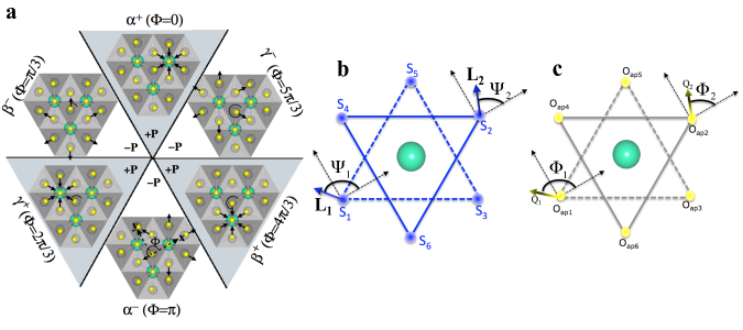
The unit cell contains two triangular layers of transition metal (TM) ions. Within the layer α𝛼\alpha (α=𝛼absent\alpha=I, II) a local magnetic structure is a combination of 120 antiferromagnetic order in the xy𝑥𝑦xy plane and a magnetization along the z𝑧z axis, Mαzsuperscriptsubscript𝑀𝛼𝑧M_{\alpha}^{z}. The former can be represented by a complex order parameter

Lα=LxyeiΨαsubscript𝐿𝛼subscript𝐿𝑥𝑦superscript𝑒𝑖subscriptΨ𝛼L_{\alpha}=L_{xy}e^{i\Psi_{\alpha}} (11)

where the angles ΨIsubscriptΨI\Psi_{\rm I} and ΨIIsubscriptΨII\Psi_{\rm II} describe in-plane spin directions of two reference TM ions, as we consider S1subscript𝑆1S_{1} and S2subscript𝑆2S_{2} respectively, from adjacent layers connected by the 2~csubscript~2𝑐\tilde{2}_{c} axis that remains in the FE phase, see Fig. 4b. Therefore ΨIΨ1subscriptΨIsubscriptΨ1\Psi_{\rm I}\equiv\Psi_{1} and ΨIIΨ2subscriptΨIIsubscriptΨ2\Psi_{\rm II}\equiv\Psi_{2}. Note that because of symmetry we only need to consider one of the three spins in each layer.

The layer magnetizations can be alternatively represented by the z𝑧z components of the net magnetization (Mz(MIz+MIIz)/2subscript𝑀𝑧superscriptsubscript𝑀I𝑧superscriptsubscript𝑀II𝑧2M_{z}\equiv(M_{\rm I}^{z}+M_{\rm II}^{z})/2) and staggered magnetization (Lz(MIzMIIz)/2subscript𝐿𝑧superscriptsubscript𝑀I𝑧superscriptsubscript𝑀II𝑧2L_{z}\equiv(M_{\rm I}^{z}-M_{\rm II}^{z})/2).

The trimer distortion corresponds to the condensation of the zone-boundary K3subscript𝐾3K_{3} mode. While the small representation of K3subscript𝐾3K_{3} is one-dimensional, the star contains two wavevectors (𝐤𝐤\mathbf{k} and 𝐤𝐤-\mathbf{k}) and therefore the trimer distortion can be described by a complex order parameter

QI=QK3eiΦ1subscript𝑄Isubscript𝑄subscript𝐾3superscript𝑒𝑖subscriptΦ1Q_{\rm I}=Q_{K_{3}}e^{i\Phi_{1}} (12)

It turns out that Φ1ΦsubscriptΦ1Φ\Phi_{1}\equiv\Phi transforms as the phase angle that describes the in-plane displacement of some reference apical oxygen in the FE phase which we choose to lie directly above the reference TM ion used for defining Ψ1subscriptΨ1\Psi_{1}, , see Fig. 4b and c. While the order parameter QIsubscript𝑄IQ_{\rm I} fully describes the trimer distortion, it is convenient to introduce additional trimer order parameter

QII=QK3eiΦ2subscript𝑄IIsubscript𝑄subscript𝐾3superscript𝑒𝑖subscriptΦ2Q_{\rm II}=Q_{K_{3}}e^{i\Phi_{2}} (13)

with Φ2=πΦ1subscriptΦ2𝜋subscriptΦ1\Phi_{2}=\pi-\Phi_{1}. As shown in Fig. 4c, Φ2subscriptΦ2\Phi_{2} describes the in-plane displacement of the apical oxygen lying directly above the reference TM ion used for defining Ψ2subscriptΨ2\Psi_{2}. The introduction of the second trimer order parameter allows us to represent the structural distortion in an analogous way as the magnetic ordering which will lead to a particularly transparent form of coupling between structure and magnetism.

The character table below shows the transformation properties of the Lαsubscript𝐿𝛼L_{\alpha} and Qαsubscript𝑄𝛼Q_{\alpha} order parameters as well as their complex conjugates with respect to symmetry operations of the P63/mmc1’ reference structure (included are only the symmetry elements that are broken by the magnetic and/or the trimer orderings). In addition, the transformation properties of the following combinations of these order parameters are shown

Xη=QILI+ηQIILIIsubscript𝑋𝜂subscript𝑄Isubscriptsuperscript𝐿I𝜂subscript𝑄IIsubscriptsuperscript𝐿IIX_{\eta}=Q_{\rm I}L^{*}_{\rm I}+\eta Q_{\rm II}L^{*}_{\rm II} (14)

where η=±𝜂plus-or-minus\eta=\pm. Note that Xηsubscript𝑋𝜂X_{\eta} are the only bilinear combinations of antiferromagnetic and trimer order parameters that are invariant under translation. The transformation properties of Mzsubscript𝑀𝑧M_{z}, Lzsubscript𝐿𝑧L_{z}, and the z𝑧z components of the electric polarization (Pzsubscript𝑃𝑧P_{z}) are also shown.

Table 1: The character table showing the transformation properties of Lαsubscript𝐿𝛼L_{\alpha} and Qαsubscript𝑄𝛼Q_{\alpha} order parameters as well as their complex conjugates with respect to symmetry operations of the P63/mmc1’ reference structure. In addition the transformation properties of Xηsubscript𝑋𝜂X_{\eta}, Pzsubscript𝑃𝑧P_{z}, Mzsubscript𝑀𝑧M_{z}, and Lzsubscript𝐿𝑧L_{z} are shown. We defined η=±𝜂plus-or-minus\eta=\pm and ϕ=ei2π/3italic-ϕsuperscript𝑒𝑖2𝜋3\phi=e^{-i2\pi/3}

.

Sxsubscript𝑆𝑥S_{x} 2~csubscript~2𝑐\tilde{2}_{c} mxysubscript𝑚𝑥𝑦m_{xy} I𝐼I R𝑅R
Pzsubscript𝑃𝑧P_{z} +Pzsubscript𝑃𝑧+P_{z} +Pzsubscript𝑃𝑧+P_{z} +Pzsubscript𝑃𝑧+P_{z} Pzsubscript𝑃𝑧-P_{z} +Pzsubscript𝑃𝑧+P_{z}
QIsubscript𝑄IQ_{\rm I} ϕQIitalic-ϕsubscript𝑄I\phi Q_{\rm I} QIIsubscript𝑄II-Q_{\rm II} +QIsubscriptsuperscript𝑄I+Q^{*}_{\rm I} +QIIsubscript𝑄II+Q_{\rm II} +QIsubscript𝑄I+Q_{\rm I}
Q1subscriptsuperscript𝑄1Q^{*}_{1} ϕQIsuperscriptitalic-ϕsubscriptsuperscript𝑄I\phi^{*}Q^{*}_{\rm I} QIIsubscriptsuperscript𝑄II-Q^{*}_{\rm II} +QIsubscript𝑄I+Q_{\rm I} +QIIsubscriptsuperscript𝑄II+Q^{*}_{\rm II} +QIsubscriptsuperscript𝑄I+Q^{*}_{\rm I}
QIIsubscript𝑄IIQ_{\rm II} ϕQIIsuperscriptitalic-ϕsubscript𝑄II\phi^{*}Q_{\rm II} QIsubscript𝑄I-Q_{\rm I} +QIIsubscriptsuperscript𝑄II+Q^{*}_{\rm II} +QIsubscript𝑄I+Q_{\rm I} +QIIsubscript𝑄II+Q_{\rm II}
QIIsubscriptsuperscript𝑄IIQ^{*}_{\rm II} ϕQIIitalic-ϕsubscriptsuperscript𝑄II\phi Q^{*}_{\rm II} QIsubscriptsuperscript𝑄I-Q^{*}_{\rm I} +QIIsubscript𝑄II+Q_{\rm II} +QIsubscriptsuperscript𝑄I+Q^{*}_{\rm I} +QIIsubscriptsuperscript𝑄II+Q^{*}_{\rm II}
LIsubscript𝐿IL_{\rm I} ϕLIitalic-ϕsubscript𝐿I\phi L_{\rm I} LIIsubscript𝐿II-L_{\rm II} LIsubscriptsuperscript𝐿I-L^{*}_{\rm I} +LIIsubscript𝐿II+L_{\rm II} LIsubscript𝐿I-L_{\rm I}
LIsubscriptsuperscript𝐿IL^{*}_{\rm I} ϕLIsuperscriptitalic-ϕsubscriptsuperscript𝐿I\phi^{*}L^{*}_{\rm I} LIIsubscriptsuperscript𝐿II-L^{*}_{\rm II} LIsubscript𝐿I-L_{\rm I} +LIIsubscriptsuperscript𝐿II+L^{*}_{\rm II} LIsubscriptsuperscript𝐿I-L^{*}_{\rm I}
LIIsubscript𝐿IIL_{\rm II} ϕLIIsuperscriptitalic-ϕsubscript𝐿II\phi^{*}L_{\rm II} LIsubscript𝐿I-L_{\rm I} LIIsubscriptsuperscript𝐿II-L^{*}_{\rm II} +LIsubscript𝐿I+L_{\rm I} LIIsubscript𝐿II-L_{\rm II}
LIIsubscriptsuperscript𝐿IIL^{*}_{\rm II} ϕLIIitalic-ϕsubscriptsuperscript𝐿II\phi L^{*}_{\rm II} LIsubscriptsuperscript𝐿I-L^{*}_{\rm I} LIIsubscript𝐿II-L_{\rm II} +LIsubscriptsuperscript𝐿I+L^{*}_{\rm I} LIIsubscriptsuperscript𝐿II-L^{*}_{\rm II}
Xηsubscript𝑋𝜂X_{\eta} +Xηsubscript𝑋𝜂+X_{\eta} ηXη𝜂subscript𝑋𝜂\eta X_{\eta} Xηsubscriptsuperscript𝑋𝜂-X^{*}_{\eta} ηXη𝜂subscript𝑋𝜂\eta X_{\eta} Xηsubscript𝑋𝜂-X_{\eta}
Mzsubscript𝑀𝑧M_{z} +Mzsubscript𝑀𝑧+M_{z} +Mzsubscript𝑀𝑧+M_{z} Mzsubscript𝑀𝑧-M_{z} +Mzsubscript𝑀𝑧+M_{z} Mzsubscript𝑀𝑧-M_{z}
Lzsubscript𝐿𝑧L_{z} +Lzsubscript𝐿𝑧+L_{z} Lzsubscript𝐿𝑧-L_{z} Lzsubscript𝐿𝑧-L_{z} Lzsubscript𝐿𝑧-L_{z} Lzsubscript𝐿𝑧-L_{z}

From the above table it is clear that the following two free energy invariants are allowed:

FtriMz[X+]Mzsimilar-tosubscriptsuperscript𝐹subscript𝑀𝑧trisubscript𝑋subscript𝑀𝑧F^{M_{z}}_{\text{tri}}\sim\Re[X_{+}]M_{z} (15)
FtriLz[X]Lzsimilar-tosubscriptsuperscript𝐹subscript𝐿𝑧trisubscript𝑋subscript𝐿𝑧F^{L_{z}}_{\text{tri}}\sim\Re[X_{-}]L_{z} (16)

where \Re denotes a real part. These invariants can be alternatively written as

FtriMzsubscriptsuperscript𝐹subscript𝑀𝑧tri\displaystyle F^{M_{z}}_{\text{tri}} proportional-to\displaystyle\propto (𝐐I𝐋I+𝐐II𝐋II)Mzsubscript𝐐Isubscript𝐋Isubscript𝐐IIsubscript𝐋IIsubscript𝑀𝑧\displaystyle(\mathbf{Q}_{\rm I}\cdot\mathbf{L}_{\rm I}+\mathbf{Q}_{\rm II}\cdot\mathbf{L}_{\rm II})M_{z} (17)
FtriLzsubscriptsuperscript𝐹subscript𝐿𝑧tri\displaystyle F^{L_{z}}_{\text{tri}} proportional-to\displaystyle\propto (𝐐I𝐋I𝐐II𝐋II)Lzsubscript𝐐Isubscript𝐋Isubscript𝐐IIsubscript𝐋IIsubscript𝐿𝑧\displaystyle(\mathbf{Q}_{\rm I}\cdot\mathbf{L}_{\rm I}-\mathbf{Q}_{\rm II}\cdot\mathbf{L}_{\rm II})L_{z} (18)

where we defined two-dimensional real vectors 𝐋α=Lxy(cosΨα,sinΨα)subscript𝐋𝛼subscript𝐿𝑥𝑦subscriptΨ𝛼subscriptΨ𝛼\mathbf{L}_{\alpha}=L_{xy}(\cos{\Psi_{\alpha}},\sin{\Psi_{\alpha}}) and 𝐐α=QK3(cosΦα,sinΦα)subscript𝐐𝛼subscript𝑄subscript𝐾3subscriptΦ𝛼subscriptΦ𝛼\mathbf{Q}_{\alpha}=Q_{K_{3}}(\cos{\Phi_{\alpha}},\sin{\Phi_{\alpha}}). As a consequence of this trilinear coupling, presence of the trimer distortion and the 120 antiferromagnetic order leads to weak (anti)ferromagnetism with (staggered) magnetization given by

Mzsubscript𝑀𝑧\displaystyle M_{z} proportional-to\displaystyle\propto (𝐐I𝐋I+𝐐II𝐋II)subscript𝐐Isubscript𝐋Isubscript𝐐IIsubscript𝐋II\displaystyle(\mathbf{Q}_{\rm I}\cdot\mathbf{L}_{\rm I}+\mathbf{Q}_{\rm II}\cdot\mathbf{L}_{\rm II}) (19)
Lzsubscript𝐿𝑧\displaystyle L_{z} proportional-to\displaystyle\propto (𝐐I𝐋I𝐐II𝐋II)subscript𝐐Isubscript𝐋Isubscript𝐐IIsubscript𝐋II\displaystyle(\mathbf{Q}_{\rm I}\cdot\mathbf{L}_{\rm I}-\mathbf{Q}_{\rm II}\cdot\mathbf{L}_{\rm II}) (20)

Note that due to equivalence of TM ion layers we have |MIz|=|MIIz|superscriptsubscript𝑀I𝑧superscriptsubscript𝑀II𝑧|M_{\rm I}^{z}|=|M_{\rm II}^{z}| which in turn implies that the proportionality coefficients in Eqs. (19) and (20) are equal. Therefore, by adding and subtracting Eqs. (19) and (20) we obtain

Mαz𝐐α𝐋αproportional-tosuperscriptsubscript𝑀𝛼𝑧subscript𝐐𝛼subscript𝐋𝛼M_{\alpha}^{z}\propto\mathbf{Q}_{\alpha}\cdot\mathbf{L}_{\alpha} (21)

where the proportionality coefficient doesn’t depend on α𝛼\alpha. The above equation clearly shows that for a given TM ion layer canting appears when a projection of an xy𝑥𝑦xy-spin along the direction of the local trimer distortion is nonzero which is for any spin configuration except A1 and B2 structures. Further, if the projection have the same sign for adjacent layers (A spin configurations) there is a net magnetization while if for neighboring layers the projections have opposite signs (B spin configurations) we have weak anti ferromagnetism.

In order to make a connection of the phenomenological theory with our microscopic model let’s define the vector 𝐝αeffsubscriptsuperscript𝐝eff𝛼\mathbf{d}^{\rm eff}_{\alpha} by 𝐐α=𝐳^×𝐝αeffsubscript𝐐𝛼^𝐳subscriptsuperscript𝐝eff𝛼\mathbf{Q}_{\alpha}=\hat{\mathbf{z}}\times\mathbf{d}^{\rm eff}_{\alpha}. Then invariants (17) and (18) can be written as

FtriMzsubscriptsuperscript𝐹subscript𝑀𝑧tri\displaystyle F^{M_{z}}_{\text{tri}} proportional-to\displaystyle\propto (𝐝Ieff(𝐋I×𝐳^)+𝐝IIeff(𝐋II×𝐳^))Mzsubscriptsuperscript𝐝effIsubscript𝐋I^𝐳subscriptsuperscript𝐝effIIsubscript𝐋II^𝐳subscript𝑀𝑧\displaystyle(\mathbf{d}^{\rm eff}_{\rm I}\cdot(\mathbf{L}_{\rm I}\times\hat{\mathbf{z}})+\mathbf{d}^{\rm eff}_{\rm II}\cdot(\mathbf{L}_{\rm II}\times\hat{\mathbf{z}}))M_{z} (22)
FtriLzsubscriptsuperscript𝐹subscript𝐿𝑧tri\displaystyle F^{L_{z}}_{\text{tri}} proportional-to\displaystyle\propto (𝐝Ieff(𝐋I×𝐳^)𝐝IIeff(𝐋II×𝐳^))Lzsubscriptsuperscript𝐝effIsubscript𝐋I^𝐳subscriptsuperscript𝐝effIIsubscript𝐋II^𝐳subscript𝐿𝑧\displaystyle(\mathbf{d}^{\rm eff}_{\rm I}\cdot(\mathbf{L}_{\rm I}\times\hat{\mathbf{z}})-\mathbf{d}^{\rm eff}_{\rm II}\cdot(\mathbf{L}_{\rm II}\times\hat{\mathbf{z}}))L_{z} (23)

while the layer magnetization is given by

Mαz𝐝αeff(𝐋α×𝐳^)proportional-tosuperscriptsubscript𝑀𝛼𝑧subscriptsuperscript𝐝eff𝛼subscript𝐋𝛼^𝐳M_{\alpha}^{z}\propto\mathbf{d}^{\rm eff}_{\alpha}\cdot(\mathbf{L}_{\alpha}\times\hat{\mathbf{z}}) (24)

Where 𝐝Ieff𝐝1effsubscriptsuperscript𝐝effIsubscriptsuperscript𝐝eff1\mathbf{d}^{\rm eff}_{\rm I}\equiv\mathbf{d}^{\rm eff}_{\rm 1} and 𝐝IIeff𝐝2effsubscriptsuperscript𝐝effIIsubscriptsuperscript𝐝eff2\mathbf{d}^{\rm eff}_{\rm II}\equiv\mathbf{d}^{\rm eff}_{\rm 2}. We can thus interpret 𝐝αeffsubscriptsuperscript𝐝eff𝛼\mathbf{d}^{\rm eff}_{\alpha} as an effective Dzyaloshinskii-Moriya (DM) vector for layer α𝛼\alpha. We will show in the next section that 𝐝αeffsubscriptsuperscript𝐝eff𝛼\mathbf{d}^{\rm eff}_{\alpha} originates from the transverse component of the DM interaction and off-diagonal elements of the single-ion anisotropy (SIA) tensor which are both induced by the trimerization distortion.

VII.2 Spin-Lattice coupling from the Dzyaloshinskii-Moriya interaction and Single-Ion Anisotropy

The Dzyaloshinskii-Moriya interaction of a single layer of bipyramids: We considered only in-plane nearest-neighbor (nn) DM interactions which are mediated by TM-Oeqeq{}_{\text{eq}}-TM paths (here Oeqeq{}_{\text{eq}} denotes an equatorial oxygen atom). In the paraelectric phase all nn DM vectors are equivalent and only their z𝑧z components are nonzero. Note that the σzsubscript𝜎𝑧\sigma_{z} mirror plane requires DM vectors for adjacent TM-TM bonds to be opposite, see Fig. 5a. Physically this is a result of different chiralities of TM-Oeqeq{}_{\text{eq}}-TM hopping paths for these DM vectors. The z𝑧z components of the DM vectors confine the spins within the xy𝑥𝑦xy plane and don’t contribute to canting. They are thus ignored in the following discussion.

In the ferroelectric phase we have two nonequivalent equatorial oxygens: Oeq1subscriptsuperscriptabsent1eq{}^{1}_{\text{eq}} and Oeq2subscriptsuperscriptabsent2eq{}^{2}_{\text{eq}}. Consequently, the nn DM vectors split into two nonequivalent types: one mediated by a TM-Oeq1subscriptsuperscriptabsent1eq{}^{1}_{\text{eq}}-TM path and the other mediated by a TM-Oeq2subscriptsuperscriptabsent2eq{}^{2}_{\text{eq}}-TM path. In addition, both types of DM vectors acquire a nonzero transverse (xy𝑥𝑦xy) component which is perpendicular to the corresponding TM-TM bond. Note that for DM vectors mediated by TM-Oeq2subscriptsuperscriptabsent2eq{}^{2}_{\text{eq}}-TM path the component parallel to the TM-TM bond is, in general, allowed by symmetry due to different orientations of apical oxygen displacements for the two TM ions. However, since apical oxygens have minor effect on TM-TM hopping, the parallel component is small which was confirmed by our first principles calculations. In the following we thus neglected the parallel component to obtain clearer picture of DM interactions. We point out, however, that the inclusion of the parallel component doesn’t affect our main conclusions. Transverse components of DM vectors between TM site 1 (see Fig. 5a) and its nearest neighbors for different trimer domains are shown in Table  2.

Table 2: Transverse components of DM vectors between TM site 1 (see Fig. 5a) and its nearest neighbors for different trimer domains.
ΦΦ\Phi 𝐃13xysuperscriptsubscript𝐃13𝑥𝑦\mathbf{D}_{13}^{xy} 𝐃13xysuperscriptsubscript𝐃superscript13𝑥𝑦\mathbf{D}_{13^{\prime}}^{xy} 𝐃13′′xysuperscriptsubscript𝐃superscript13′′𝑥𝑦\mathbf{D}_{13^{\prime\prime}}^{xy}
00 Dxy(12,32)subscript𝐷𝑥𝑦1232D_{xy}(-\frac{1}{2},-\frac{\sqrt{3}}{2}) Dxy(1,0)subscriptsuperscript𝐷𝑥𝑦10D^{\prime}_{xy}(-1,0) Dxy(12,32)subscriptsuperscript𝐷𝑥𝑦1232D^{\prime}_{xy}(\frac{1}{2},-\frac{\sqrt{3}}{2})
π/3𝜋3\pi/3 Dxy(12,32)subscriptsuperscript𝐷𝑥𝑦1232D^{\prime}_{xy}(-\frac{1}{2},-\frac{\sqrt{3}}{2}) Dxy(1,0)subscriptsuperscript𝐷𝑥𝑦10D^{\prime}_{xy}(1,0) Dxy(12,32)subscript𝐷𝑥𝑦1232D_{xy}(\frac{1}{2},-\frac{\sqrt{3}}{2})
2π/32𝜋32\pi/3 Dxy(12,32)subscriptsuperscript𝐷𝑥𝑦1232D^{\prime}_{xy}(\frac{1}{2},\frac{\sqrt{3}}{2}) Dxy(1,0)subscript𝐷𝑥𝑦10D_{xy}(1,0) Dxy(12,32)subscriptsuperscript𝐷𝑥𝑦1232D^{\prime}_{xy}(\frac{1}{2},-\frac{\sqrt{3}}{2})
π𝜋\pi Dxy(12,32)subscript𝐷𝑥𝑦1232D_{xy}(\frac{1}{2},\frac{\sqrt{3}}{2}) Dxy(1,0)subscriptsuperscript𝐷𝑥𝑦10D^{\prime}_{xy}(1,0) Dxy(12,32)subscriptsuperscript𝐷𝑥𝑦1232D^{\prime}_{xy}(-\frac{1}{2},\frac{\sqrt{3}}{2})
4π/34𝜋34\pi/3 Dxy(12,32)subscriptsuperscript𝐷𝑥𝑦1232D^{\prime}_{xy}(\frac{1}{2},\frac{\sqrt{3}}{2}) Dxy(1,0)subscriptsuperscript𝐷𝑥𝑦10D^{\prime}_{xy}(-1,0) Dxy(12,32)subscript𝐷𝑥𝑦1232D_{xy}(-\frac{1}{2},\frac{\sqrt{3}}{2})
5π/35𝜋35\pi/3 Dxy(12,32)subscriptsuperscript𝐷𝑥𝑦1232D^{\prime}_{xy}(-\frac{1}{2},-\frac{\sqrt{3}}{2}) Dxy(1,0)subscript𝐷𝑥𝑦10D_{xy}(-1,0) Dxy(12,32)subscriptsuperscript𝐷𝑥𝑦1232D^{\prime}_{xy}(-\frac{1}{2},\frac{\sqrt{3}}{2})
ΦΦ\Phi 𝐃15xysuperscriptsubscript𝐃15𝑥𝑦\mathbf{D}_{15}^{xy} 𝐃15xysuperscriptsubscript𝐃superscript15𝑥𝑦\mathbf{D}_{15^{\prime}}^{xy} 𝐃15′′xysuperscriptsubscript𝐃superscript15′′𝑥𝑦\mathbf{D}_{15^{\prime\prime}}^{xy}
00 Dxy(12,32)subscript𝐷𝑥𝑦1232D_{xy}(\frac{1}{2},-\frac{\sqrt{3}}{2}) Dxy(12,32)subscriptsuperscript𝐷𝑥𝑦1232D^{\prime}_{xy}(-\frac{1}{2},-\frac{\sqrt{3}}{2}) Dxy(1,0)subscriptsuperscript𝐷𝑥𝑦10D^{\prime}_{xy}(1,0)
π/3𝜋3\pi/3 Dxy(12,32)subscriptsuperscript𝐷𝑥𝑦1232D^{\prime}_{xy}(\frac{1}{2},-\frac{\sqrt{3}}{2}) Dxy(12,32)subscriptsuperscript𝐷𝑥𝑦1232D^{\prime}_{xy}(\frac{1}{2},\frac{\sqrt{3}}{2}) Dxy(1,0)subscript𝐷𝑥𝑦10D_{xy}(1,0)
2π/32𝜋32\pi/3 Dxy(12,32)subscriptsuperscript𝐷𝑥𝑦1232D^{\prime}_{xy}(-\frac{1}{2},\frac{\sqrt{3}}{2}) Dxy(12,32)subscript𝐷𝑥𝑦1232D_{xy}(\frac{1}{2},\frac{\sqrt{3}}{2}) Dxy(1,0)subscriptsuperscript𝐷𝑥𝑦10D^{\prime}_{xy}(1,0)
π𝜋\pi Dxy(12,32)subscript𝐷𝑥𝑦1232D_{xy}(-\frac{1}{2},\frac{\sqrt{3}}{2}) Dxy(12,32)subscriptsuperscript𝐷𝑥𝑦1232D^{\prime}_{xy}(\frac{1}{2},\frac{\sqrt{3}}{2}) Dxy(1,0)subscriptsuperscript𝐷𝑥𝑦10D^{\prime}_{xy}(-1,0)
4π/34𝜋34\pi/3 Dxy(12,32)subscriptsuperscript𝐷𝑥𝑦1232D^{\prime}_{xy}(-\frac{1}{2},\frac{\sqrt{3}}{2}) Dxy(12,32)subscriptsuperscript𝐷𝑥𝑦1232D^{\prime}_{xy}(-\frac{1}{2},-\frac{\sqrt{3}}{2}) Dxy(1,0)subscript𝐷𝑥𝑦10D_{xy}(-1,0)
5π/35𝜋35\pi/3 Dxy(12,32)subscriptsuperscript𝐷𝑥𝑦1232D^{\prime}_{xy}(\frac{1}{2},-\frac{\sqrt{3}}{2}) Dxy(12,32)subscript𝐷𝑥𝑦1232D_{xy}(-\frac{1}{2},-\frac{\sqrt{3}}{2}) Dxy(1,0)subscriptsuperscript𝐷𝑥𝑦10D^{\prime}_{xy}(-1,0)
Refer to caption
Figure 5: Dzyaloshinskii-Moriya interactions and Single-Ion Anisotropy. a The in-plane nn DM vectors for a single triangular layer of TM ions, b SIA tensors for the paraelectric phase and for two opposite directions of the trimer distortion in the ferroelectric phase. All six DM vectors acting on TM site 1 and SIA tensor for this site are shown. DM vectors and SIA tensors for other bonds and sites can be generated by applying the appropriate symmetry operations of crystal space group. In the paraelectric phase only the z𝑧z component of the nn DM vectors are non-zero since triangular layers are mirror planes. The cross (dot) mark represents direction of a DM vector along positive (negative) z^^𝑧\hat{z} axis. In the ferroelectric structure, the trimer distortion lowers the symmetry, leading to two nonequivalent types of in-plane nn DM vectors: one mediated by TM-O1psuperscriptsubscriptabsent𝑝1{}_{p}^{1}-TM path and the other mediated by TM-O2psuperscriptsubscriptabsent𝑝2{}_{p}^{2}-TM path.

Here we derive the relationship between the local structural distortions and the induced 𝐃ijxysubscriptsuperscript𝐃𝑥𝑦𝑖𝑗\mathbf{D}^{xy}_{ij}. Let’s consider the layer α=𝛼absent\alpha= I. The DM interaction energy (per spin) is given by (see notation in Fig. 5a)

EIDMsuperscriptsubscript𝐸IDM\displaystyle E_{\rm I}^{\text{DM}} =\displaystyle= 23(𝐃13xy+𝐃13xy+𝐃13′′xy)(𝐒1×𝐒3)+23(𝐃35xy+𝐃35′′xy+𝐃35xy)(𝐒3×𝐒5)+23(𝐃51xy+𝐃51xy+𝐃5′′1xy)(𝐒5×𝐒1)23superscriptsubscript𝐃13𝑥𝑦superscriptsubscript𝐃superscript13𝑥𝑦superscriptsubscript𝐃superscript13′′𝑥𝑦subscript𝐒1subscript𝐒323superscriptsubscript𝐃35𝑥𝑦superscriptsubscript𝐃superscript35′′𝑥𝑦superscriptsubscript𝐃superscript35𝑥𝑦subscript𝐒3subscript𝐒523superscriptsubscript𝐃51𝑥𝑦superscriptsubscript𝐃superscript51𝑥𝑦superscriptsubscript𝐃superscript5′′1𝑥𝑦subscript𝐒5subscript𝐒1\displaystyle\frac{2}{3}(\mathbf{D}_{13}^{xy}+\mathbf{D}_{13^{\prime}}^{xy}+\mathbf{D}_{13^{\prime\prime}}^{xy})\cdot(\mathbf{S}_{1}\times\mathbf{S}_{3})+\frac{2}{3}(\mathbf{D}_{35}^{xy}+\mathbf{D}_{35^{\prime\prime}}^{xy}+\mathbf{D}_{3^{\prime}5}^{xy})\cdot(\mathbf{S}_{3}\times\mathbf{S}_{5})+\frac{2}{3}(\mathbf{D}_{51}^{xy}+\mathbf{D}_{5^{\prime}1}^{xy}+\mathbf{D}_{5^{\prime\prime}1}^{xy})\cdot(\mathbf{S}_{5}\times\mathbf{S}_{1}) (25)
=\displaystyle= 23𝐃¯13(𝐒1×𝐒3)+23𝐃¯35(𝐒3×𝐒5)+23𝐃¯51(𝐒5×𝐒1)23subscript¯𝐃13subscript𝐒1subscript𝐒323subscript¯𝐃35subscript𝐒3subscript𝐒523subscript¯𝐃51subscript𝐒5subscript𝐒1\displaystyle\frac{2}{3}\mathbf{\bar{D}}_{13}\cdot(\mathbf{S}_{1}\times\mathbf{S}_{3})+\frac{2}{3}\mathbf{\bar{D}}_{35}\cdot(\mathbf{S}_{3}\times\mathbf{S}_{5})+\frac{2}{3}\mathbf{\bar{D}}_{51}\cdot(\mathbf{S}_{5}\times\mathbf{S}_{1})

where we defined the bar DM vectors

𝐃¯13subscript¯𝐃13\displaystyle\mathbf{\bar{D}}_{13} \displaystyle\equiv 𝐃13xy+𝐃13xy+𝐃13′′xy=D¯xy(cos(Φ2π/3),sin(Φ2π/3))superscriptsubscript𝐃13𝑥𝑦superscriptsubscript𝐃superscript13𝑥𝑦superscriptsubscript𝐃superscript13′′𝑥𝑦subscript¯𝐷𝑥𝑦Φ2𝜋3Φ2𝜋3\displaystyle\mathbf{D}_{13}^{xy}+\mathbf{D}_{13^{\prime}}^{xy}+\mathbf{D}_{13^{\prime\prime}}^{xy}=\bar{D}_{xy}\left(\cos(\Phi-2\pi/3),\sin(\Phi-2\pi/3)\right) (26)
𝐃¯35subscript¯𝐃35\displaystyle\mathbf{\bar{D}}_{35} \displaystyle\equiv 𝐃35xy+𝐃35′′xy+𝐃35xy=D¯xy(cos(Φ),sin(Φ))superscriptsubscript𝐃35𝑥𝑦superscriptsubscript𝐃superscript35′′𝑥𝑦superscriptsubscript𝐃superscript35𝑥𝑦subscript¯𝐷𝑥𝑦ΦΦ\displaystyle\mathbf{D}_{35}^{xy}+\mathbf{D}_{35^{\prime\prime}}^{xy}+\mathbf{D}_{3^{\prime}5}^{xy}=\bar{D}_{xy}\left(\cos(\Phi),\sin(\Phi)\right) (27)
𝐃¯51subscript¯𝐃51\displaystyle\mathbf{\bar{D}}_{51} \displaystyle\equiv 𝐃51xy+𝐃51xy+𝐃5′′1xy)=D¯xy(cos(Φ+2π/3),sin(Φ+2π/3))\displaystyle\mathbf{D}_{51}^{xy}+\mathbf{D}_{5^{\prime}1}^{xy}+\mathbf{D}_{5^{\prime\prime}1}^{xy})=\bar{D}_{xy}\left(\cos(\Phi+2\pi/3),\sin(\Phi+2\pi/3)\right) (28)

with D¯xy=Dxy+Dxysubscript¯𝐷𝑥𝑦subscript𝐷𝑥𝑦subscriptsuperscript𝐷𝑥𝑦\bar{D}_{xy}=D_{xy}+D^{\prime}_{xy}. The above expressions can be easily obtained from Table 2 or Fig. 5a. Note that the bar DM vectors have magnitude D¯xysubscript¯𝐷𝑥𝑦\bar{D}_{xy} and form a 120 angle with each other.

Therefore, a much simpler picture emerges; the relationship between the local structural distortions and the induced 𝐃ijxysubscriptsuperscript𝐃𝑥𝑦𝑖𝑗\mathbf{D}^{xy}_{ij} can be derived by considering a single triangle of spins (𝐒1subscript𝐒1\mathbf{S}_{1}, 𝐒3subscript𝐒3\mathbf{S}_{3} and 𝐒5subscript𝐒5\mathbf{S}_{5}) interacting by the bar DM vectors, see Fig. 6 for the case of the α+superscript𝛼\alpha^{+} and αsuperscript𝛼\alpha^{-} domains.

Since all spins cant in the same direction we can write 𝐒i=𝐋i+𝐌Isubscript𝐒𝑖subscript𝐋𝑖subscript𝐌I\mathbf{S}_{i}=\mathbf{L}_{i}+\mathbf{M}_{\rm I} where 𝐋isubscript𝐋𝑖\mathbf{L}_{i} are defined in Fig. 1d of the main manuscript and 𝐌Isubscript𝐌I\mathbf{M}_{\rm I} is the parallel to the z𝑧z axis layer magnetization. We then obtain

EIDM=23(𝐃¯13+𝐃¯15)(𝐋1×𝐌I)+23(𝐃¯35+𝐃¯31)(𝐋3×𝐌I)+23(𝐃¯51+𝐃¯53)(𝐋5×𝐌I)=13i=1,3,5𝐝i[𝐋i×𝐌I]superscriptsubscript𝐸IDM23subscript¯𝐃13subscript¯𝐃15subscript𝐋1subscript𝐌I23subscript¯𝐃35subscript¯𝐃31subscript𝐋3subscript𝐌I23subscript¯𝐃51subscript¯𝐃53subscript𝐋5subscript𝐌I13subscript𝑖135subscript𝐝𝑖delimited-[]subscript𝐋𝑖subscript𝐌IE_{\rm I}^{\text{DM}}=\frac{2}{3}(\mathbf{\bar{D}}_{13}+\mathbf{\bar{D}}_{15})\cdot(\mathbf{L}_{1}\times\mathbf{M}_{\rm I})+\frac{2}{3}(\mathbf{\bar{D}}_{35}+\mathbf{\bar{D}}_{31})\cdot(\mathbf{L}_{3}\times\mathbf{M}_{\rm I})+\frac{2}{3}(\mathbf{\bar{D}}_{51}+\mathbf{\bar{D}}_{53})\cdot(\mathbf{L}_{5}\times\mathbf{M}_{\rm I})=\frac{1}{3}\sum_{i=1,3,5}\mathbf{d}_{i}\cdot[\mathbf{L}_{i}\times\mathbf{M}_{\rm I}] (29)

where the 𝐝isubscript𝐝𝑖\mathbf{d}_{i}’s, e.g., 𝐝12(𝐃¯13+𝐃¯15)subscript𝐝12subscript¯𝐃13subscript¯𝐃15\mathbf{d}_{1}\equiv 2(\mathbf{\bar{D}}_{13}+\mathbf{\bar{D}}_{15}), are the effective, transverse DM-interactions. Using A(B×C)=B(C×A)𝐴𝐵𝐶𝐵𝐶𝐴A\cdot(B\times C)=B\cdot(C\times A) and 𝐌I=MIz𝐳^subscript𝐌Isubscriptsuperscript𝑀𝑧I^𝐳\mathbf{M}_{\rm I}=M^{z}_{\rm I}\mathbf{\hat{z}} the DM energy can be rewritten as

EIDM=13MIzi=1,3,5𝐋i[𝐳^×𝐝i]=233D¯xyMIzi=1,3,5𝐋i𝐐^isuperscriptsubscript𝐸IDM13superscriptsubscript𝑀I𝑧subscript𝑖135subscript𝐋𝑖delimited-[]^𝐳subscript𝐝𝑖233subscript¯𝐷𝑥𝑦superscriptsubscript𝑀I𝑧subscript𝑖135subscript𝐋𝑖subscript^𝐐𝑖E_{\rm I}^{\text{DM}}=\frac{1}{3}M_{\rm I}^{z}\sum_{i=1,3,5}\mathbf{L}_{i}\cdot[\mathbf{\hat{z}}\times\mathbf{d}_{i}]=\frac{2\sqrt{3}}{3}\bar{D}_{xy}M_{\rm I}^{z}\sum_{i=1,3,5}\mathbf{L}_{i}\cdot\mathbf{\hat{Q}}_{i} (30)

where we used 23D¯xy𝐐^i=𝐳^×𝐝i23subscript¯𝐷𝑥𝑦subscript^𝐐𝑖^𝐳subscript𝐝𝑖2\sqrt{3}\bar{D}_{xy}\mathbf{\hat{Q}}_{i}=\mathbf{\hat{z}}\times\mathbf{d}_{i} with 𝐐^isubscript^𝐐𝑖\mathbf{\hat{Q}}_{i}’s being unit vectors defined in Fig. 1d of the main manuscript. The relation between 𝐝isubscript𝐝𝑖\mathbf{d}_{i} and 𝐐𝐢^^subscript𝐐𝐢\mathbf{\hat{Q_{i}}} can be straightforwardly obtained from Eqs. 30 but more physical insight into this relation can be gained by noting that 𝐃ijxy𝐫^ij×𝐮Oeqproportional-tosuperscriptsubscript𝐃𝑖𝑗𝑥𝑦subscript^𝐫𝑖𝑗subscript𝐮subscriptOeq\mathbf{D}_{ij}^{xy}\propto\mathbf{\hat{r}}_{ij}\times\mathbf{u}_{\text{O}_{\text{eq}}} where 𝐫^ijsubscript^𝐫𝑖𝑗\mathbf{\hat{r}}_{ij} is the unit vector pointing from site i𝑖i towards j𝑗j and 𝐮Oeqsubscript𝐮subscriptOeq\mathbf{u}_{\text{O}_{\text{eq}}} is the displacement of the equatorial oxygen away from the plane (e.g., due to the tilting of the bipyramid) which is zero in the PE phase and parallel to the z𝑧z axis in the FE phase. For the α±superscript𝛼plus-or-minus\alpha^{\pm} trimer domains we find

𝐝1±𝐳^×(𝐫^13+𝐫^15)proportional-tosubscript𝐝1plus-or-minus^𝐳subscript^𝐫13subscript^𝐫15\mathbf{d}_{1}\propto\pm\mathbf{\hat{z}}\times(\mathbf{\hat{r}}_{13}+\mathbf{\hat{r}}_{15}) (31)

As seen from Fig. 6b, 𝐫^13+𝐫^15=𝐐^1subscript^𝐫13subscript^𝐫15subscript^𝐐1\mathbf{\hat{r}}_{13}+\mathbf{\hat{r}}_{15}=\mathbf{\hat{Q}}_{1} giving

𝐐^1±𝐳^×𝐝1proportional-tosubscript^𝐐1plus-or-minus^𝐳subscript𝐝1\mathbf{\hat{Q}}_{1}\propto\pm\mathbf{\hat{z}}\times\mathbf{d}_{1} (32)

Other 𝐝isubscript𝐝𝑖\mathbf{d}_{i} can be found by cyclic permutations: 13131\rightarrow 3, 35353\rightarrow 5, and 51515\rightarrow 1. The same results can be obtained for other trimer domains.

Note that

𝐋1𝐐^1=𝐋3𝐐^3=𝐋5𝐐^5𝐋I𝐐^I=Lxycos(ΦΨ1)subscript𝐋1subscript^𝐐1subscript𝐋3subscript^𝐐3subscript𝐋5subscript^𝐐5subscript𝐋Isubscript^𝐐Isubscript𝐿𝑥𝑦ΦsubscriptΨ1\mathbf{L}_{1}\cdot\mathbf{\hat{Q}}_{1}=\mathbf{L}_{3}\cdot\mathbf{\hat{Q}}_{3}=\mathbf{L}_{5}\cdot\mathbf{\hat{Q}}_{5}\equiv\mathbf{L}_{\rm I}\cdot\mathbf{\hat{Q}}_{\rm I}=L_{xy}\cos(\Phi-\Psi_{1}) (33)

We thus obtain

EIDM=23D¯xyMIz𝐋I𝐐^I=MIz𝐋1𝐳^×𝐝1superscriptsubscript𝐸IDM23subscript¯𝐷𝑥𝑦superscriptsubscript𝑀I𝑧subscript𝐋Isubscript^𝐐Isuperscriptsubscript𝑀I𝑧subscript𝐋1^𝐳subscript𝐝1E_{\rm I}^{\text{DM}}=2\sqrt{3}\bar{D}_{xy}M_{\rm I}^{z}\mathbf{L}_{\rm I}\cdot\mathbf{\hat{Q}}_{\rm I}=M_{\rm I}^{z}\mathbf{L}_{\rm 1}\cdot\mathbf{\hat{z}}\times\mathbf{d}_{\rm 1} (34)

which leads to

MIz𝐋1𝐳^×𝐝1=23D¯xy𝐋I𝐐^Iproportional-tosuperscriptsubscript𝑀I𝑧subscript𝐋1^𝐳subscript𝐝123subscript¯𝐷𝑥𝑦subscript𝐋Isubscript^𝐐IM_{\rm I}^{z}\propto\mathbf{L}_{1}\cdot\mathbf{\hat{z}}\times\mathbf{d}_{1}=2\sqrt{3}\bar{D}_{xy}\mathbf{L}_{\rm I}\cdot\mathbf{\hat{Q}}_{\rm I} (35)

in agreement with Eqs.21 obtained from the Landau theory. It is now clear that the microscopic origin of the layer magnetization is the the trimer induced transverse components of the DM interactions which cant spins away from the xy𝑥𝑦xy plane. As we will see in the next section, however, there is also another contribution to the canting that originates from the single-ion anisotropy (SIA).

Refer to caption
Figure 6: Microscopic: Basic ingredients to describe connection between microscopic spin-lattice model and a simple phenomenological model. a and b, local trimer distortion around S1subscriptS1\textbf{S}_{1} from two different projections. c, the transverse components of DM vectors are shown for a single triangle in a single layer. Cross and dot signs denote displacement of the equatorial oxygen along -z^^𝑧\hat{z} and +z^^𝑧\hat{z} respectively. d, demonstrates the relation Mz(L.Q)z^\textbf{M}_{z}\propto(\textbf{L}.\textbf{Q})\hat{z}.

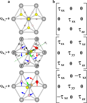
The Single-ion anisotropy of a single layer of bipyramids: In the paraelectric phase the crystal field has the same orientation for all TM ions so the single-ion anisotropy (SIA) tensor, τ^isubscript^𝜏𝑖\mathbf{\hat{\tau}}_{i}, does not depend on magnetic site index i𝑖i. A global coordinate system (see Fig. 5) can be thus chosen in which τ^^𝜏\mathbf{\hat{\tau}} is diagonal with elements τxxsuperscript𝜏𝑥𝑥\tau^{xx}, τyysuperscript𝜏𝑦𝑦\tau^{yy}, τzzsuperscript𝜏𝑧𝑧\tau^{zz}. A uniaxial site symmetry and the zero-trace condition lead to τxx=τyy=τzz/2superscript𝜏𝑥𝑥superscript𝜏𝑦𝑦superscript𝜏𝑧𝑧2\tau^{xx}=\tau^{yy}=-\tau^{zz}/2.

On the other hand, in the ferroelectric phase the crystal field may have different orientations for different TM ions and therefore τ^isubscript^𝜏𝑖\mathbf{\hat{\tau}}_{i} does depend on i𝑖i. Even though all TM ions remain equivalent and thus SIA tensors for different magnetic sites are related by symmetry, in any global coordinate system SIA tensor for some magnetic ions have off diagonal components. In addition, the uniaxial site symmetry is lost in the ferroelectric phase leading to the in-plane anisotropy (τxxτyysuperscript𝜏𝑥𝑥superscript𝜏𝑦𝑦\tau^{xx}\neq\tau^{yy}). In the coordinate system as in Fig. 5a the SIA tensor for site 1 in the Φ=0Φ0\Phi=0 trimer domain is given by

τ^=[τxx0τxz0τyy0τxz0τzz]^𝜏matrixsubscript𝜏𝑥𝑥0subscript𝜏𝑥𝑧0subscript𝜏𝑦𝑦0subscript𝜏𝑥𝑧0subscript𝜏𝑧𝑧\mathbf{\hat{\tau}}=\begin{bmatrix}\tau_{xx}&0&\tau_{xz}\\ 0&\tau_{yy}&0\\ \tau_{xz}&0&\tau_{zz}\\ \end{bmatrix} (36)

For a general trimer domain the SIA tensor for site 1 is given by RΦτ^RΦ1subscript𝑅Φ^𝜏subscriptsuperscript𝑅1ΦR_{\Phi}\mathbf{\hat{\tau}}R^{-1}_{\Phi} where RΦsubscript𝑅ΦR_{\Phi} is a rotation matrix

RΦ=[cosΦsinΦ0sinΦcosΦ0001]subscript𝑅ΦmatrixΦΦ0ΦΦ0001R_{\Phi}=\begin{bmatrix}\cos\Phi&-\sin\Phi&0\\ \sin\Phi&\cos\Phi&0\\ 0&0&1\\ \end{bmatrix} (37)

The effect of trimer distortion on the components of the SIA tensor can be understood if we assume that the crystal field for a given TM ion is determined solely by its oxygen bypyramid. In this case the components of τ^^𝜏\mathbf{\hat{\tau}} in Eq. (36) can be expressed in terms of the tilting angle θ𝜃\theta and the value of τzzsubscript𝜏𝑧𝑧\tau_{zz} in the paraelectric phase (hereafter denoted by τzz0subscriptsuperscript𝜏0𝑧𝑧\tau^{0}_{zz}). For site 1 we have:

τxx=τzz0/2subscript𝜏𝑥𝑥subscriptsuperscript𝜏0𝑧𝑧2\displaystyle\tau_{xx}=-\tau^{0}_{zz}/2 (38)
τyy=cos2(θ)τzz0/2+sin2(θ)τzz0subscript𝜏𝑦𝑦superscript2𝜃subscriptsuperscript𝜏0𝑧𝑧2superscript2𝜃subscriptsuperscript𝜏0𝑧𝑧\displaystyle\tau_{yy}=-\cos^{2}(\theta)\tau^{0}_{zz}/2+\sin^{2}(\theta)\tau^{0}_{zz} (39)
τzz=cos2(θ)τzz0sin2(θ)τzz0/2subscript𝜏𝑧𝑧superscript2𝜃subscriptsuperscript𝜏0𝑧𝑧superscript2𝜃subscriptsuperscript𝜏0𝑧𝑧2\displaystyle\tau_{zz}=\cos^{2}(\theta)\tau^{0}_{zz}-\sin^{2}(\theta)\tau^{0}_{zz}/2 (40)
τxz=3sin(2θ)τzz0/4subscript𝜏𝑥𝑧32𝜃subscriptsuperscript𝜏0𝑧𝑧4\displaystyle\tau_{xz}=-3\sin(2\theta)\tau^{0}_{zz}/4 (41)

First principles calculations show that the in-plane anisotropy is very small (see Table. 5). Indeed, as seen from Eqs. (41) this difference is proportional to sin2θsuperscript2𝜃\sin^{2}\theta which is a very small quantity. On the other hand, the off-diagonal component, τxzsubscript𝜏𝑥𝑧\tau_{xz} is proportional to sin2θ2𝜃\sin 2\theta and is correspondingly substantially larger and plays important role in the canting.

Let’s consider the SIA contribution to the canting energy (per spin) for the layer α=𝛼absent\alpha= I

EISIA=13i=1,3,5𝐒iτ^1𝐒i=23τxzMIzi=1,3,5𝐋i𝐐^i=2τxzMIz𝐋I𝐐^Isuperscriptsubscript𝐸I𝑆𝐼𝐴13subscript𝑖135subscript𝐒𝑖subscript^𝜏1subscript𝐒𝑖23subscript𝜏𝑥𝑧superscriptsubscript𝑀I𝑧subscript𝑖135subscript𝐋𝑖subscript^𝐐𝑖2subscript𝜏𝑥𝑧superscriptsubscript𝑀I𝑧subscript𝐋Isubscript^𝐐IE_{\rm I}^{SIA}=\frac{1}{3}\sum_{i=1,3,5}\mathbf{S}_{i}\cdot\mathbf{\hat{\tau}}_{1}\cdot\mathbf{S}_{i}=\frac{2}{3}\tau_{xz}M_{\rm I}^{z}\sum_{i=1,3,5}\mathbf{L}_{i}\cdot\mathbf{\hat{Q}}_{i}=2\tau_{xz}M_{\rm I}^{z}\mathbf{L}_{\rm I}\cdot\mathbf{\hat{Q}}_{\rm I} (42)

where we kept only the terms proportional to MIzsuperscriptsubscript𝑀I𝑧M_{\rm I}^{z}. The above equation has a similar form as Eq. 30. Indeed, we can define a DM-like vector 𝐝iSIAsuperscriptsubscript𝐝𝑖𝑆𝐼𝐴\mathbf{d}_{i}^{SIA} as 2τxz𝐐^i=𝐳^×𝐝iSIA2subscript𝜏𝑥𝑧subscript^𝐐𝑖^𝐳superscriptsubscript𝐝𝑖𝑆𝐼𝐴2\tau_{xz}\mathbf{\hat{Q}}_{i}=\mathbf{\hat{z}}\times\mathbf{d}_{i}^{SIA}. We then get

EISIA=13i=1,3,5𝐝iSIA[𝐋i×𝐌Iz]superscriptsubscript𝐸ISIA13subscript𝑖135superscriptsubscript𝐝𝑖𝑆𝐼𝐴delimited-[]subscript𝐋𝑖superscriptsubscript𝐌I𝑧E_{\rm I}^{\rm SIA}=\frac{1}{3}\sum_{i=1,3,5}\mathbf{d}_{i}^{SIA}\cdot[\mathbf{L}_{i}\times\mathbf{M}_{\rm I}^{z}] (43)

The total energy and magnetization of a single layer of bipyramids: Combining Eqs. (30) and (43) we obtain

EIcanting=EIDM+EISIA=13i=1,3,5𝐝ieff[𝐋i×𝐌I]superscriptsubscript𝐸Icantingsuperscriptsubscript𝐸IDMsuperscriptsubscript𝐸ISIA13subscript𝑖135subscriptsuperscript𝐝eff𝑖delimited-[]subscript𝐋𝑖subscript𝐌IE_{\rm I}^{\rm canting}=E_{\rm I}^{\rm DM}+E_{\rm I}^{\rm SIA}=\frac{1}{3}\sum_{i=1,3,5}\mathbf{d}^{\rm eff}_{i}\cdot[\mathbf{L}_{i}\times\mathbf{M}_{\rm I}] (44)

where 𝐝ieff=𝐝i+𝐝iSIAsubscriptsuperscript𝐝eff𝑖subscript𝐝𝑖superscriptsubscript𝐝𝑖𝑆𝐼𝐴\mathbf{d}^{\rm eff}_{i}=\mathbf{d}_{i}+\mathbf{d}_{i}^{SIA} is the effective transverse DM vector with the magnitude |𝐝eff|=2|3D¯xy+τxy|superscript𝐝eff23subscript¯𝐷𝑥𝑦subscript𝜏𝑥𝑦|\mathbf{d}^{\rm eff}|=2|\sqrt{3}\bar{D}_{xy}+\tau_{xy}|.

Again using A(B×C)=B(C×A)𝐴𝐵𝐶𝐵𝐶𝐴A\cdot(B\times C)=B\cdot(C\times A) and MI=MIz𝐳^subscriptMIsuperscriptsubscript𝑀I𝑧^𝐳\textbf{M}_{\rm I}=M_{\rm I}^{z}\mathbf{\hat{z}}, Ecantingsubscript𝐸cantingE_{\rm canting} can be rewritten as

EIcantingsuperscriptsubscript𝐸Icanting\displaystyle E_{\rm I}^{\rm canting} =\displaystyle= MIzi=1,3,5𝐋i[𝐳^×𝐝ieff]superscriptsubscript𝑀I𝑧subscript𝑖135subscript𝐋𝑖delimited-[]^𝐳subscriptsuperscript𝐝eff𝑖\displaystyle M_{\rm I}^{z}\sum_{i=1,3,5}\mathbf{L}_{i}\cdot[\mathbf{\hat{z}}\times\mathbf{d}^{\rm eff}_{i}] (45)
=\displaystyle= |𝐝eff|MIz𝐋I𝐐^Isuperscript𝐝effsuperscriptsubscript𝑀I𝑧subscript𝐋Isubscript^𝐐I\displaystyle|\mathbf{d}^{\rm eff}|M_{\rm I}^{z}\mathbf{L}_{\rm I}\cdot\mathbf{\hat{Q}}_{\rm I}

so that the layer magnetization due to canting is given by

MIz(3D¯xy+τxz)6Jnn𝐋I𝐐Isuperscriptsubscript𝑀I𝑧3subscript¯𝐷𝑥𝑦subscript𝜏𝑥𝑧6subscript𝐽𝑛𝑛subscript𝐋Isubscript𝐐IM_{\rm I}^{z}\approx\frac{(\sqrt{3}\bar{D}_{xy}+\tau_{xz})}{6J_{nn}}\,\,\mathbf{L}_{\rm I}\cdot\mathbf{Q}_{\rm I} (46)

where Jnnsubscript𝐽𝑛𝑛J_{nn} is the nn exchange interaction.

We thus recovered the result from Landau Theory.

The real structure: the stacking of two layers: Let us consider now a real hexa structure which is composed of two layers α=𝛼absent\alpha= I and α=𝛼absent\alpha= II, each with a, in principle different, layer magnetization, MIzsubscriptsuperscript𝑀𝑧IM^{z}_{\rm I} and MIIzsubscriptsuperscript𝑀𝑧IIM^{z}_{{\rm II}} respectively. The canting energy is

Ecanting=(EIcanting+EIIcanting)/2=|𝐝eff|[MIz(LIQI)+MIIz(LIIQII)]/2subscript𝐸cantingsuperscriptsubscript𝐸Icantingsuperscriptsubscript𝐸IIcanting2superscript𝐝effdelimited-[]subscriptsuperscript𝑀𝑧IsubscriptLIsubscriptQIsubscriptsuperscript𝑀𝑧IIsubscriptLIIsubscriptQII2E_{\rm canting}=(E_{\rm I}^{\rm canting}+E_{\rm II}^{\rm canting})/2=|\mathbf{d}^{\rm eff}|\left[M^{z}_{\rm I}(\textbf{L}_{\rm I}\cdot\textbf{Q}_{\rm I})+M^{z}_{\rm II}(\textbf{L}_{\rm II}\cdot\textbf{Q}_{\rm II})\right]/2 (47)

This result shows clearly that the B1 state displays weak-antiferromagentism, wAFM, i.e., there is a canting of the spins out of each spin plane, but since the projection changes sign in adjacent layers, i.e., LIQIsubscriptLIsubscriptQI\textbf{L}_{\rm I}\cdot\textbf{Q}_{\rm I} = -LIIQIIsubscriptLIIsubscriptQII\textbf{L}_{\rm II}\cdot\textbf{Q}_{\rm II}, no net magnetization exists, Mz=MIz+MIIz=0subscript𝑀𝑧subscriptsuperscript𝑀𝑧Isubscriptsuperscript𝑀𝑧II0{M}_{z}=M^{z}_{\rm I}+M^{z}_{\rm II}=0. In the A2 phase, however, the projection has the same sign in adjacent layers, LIQIsubscriptLIsubscriptQI\textbf{L}_{\rm I}\cdot\textbf{Q}_{\rm I} = +LIIQIIsubscriptLIIsubscriptQII\textbf{L}_{\rm II}\cdot\textbf{Q}_{\rm II}, and therefore MIz=MIIzsubscriptsuperscript𝑀𝑧Isubscriptsuperscript𝑀𝑧IIM^{z}_{\rm I}=M^{z}_{\rm II} leading to a net magnetization along the z𝑧z axis. This result explains our first-principles calculations displayed in Fig.1 of the main manuscript and provides a microscopic justification for the results of our simple Landau theory.

The above results can be rewritten in terms of the trimer phase and the spin angles

EcantingA2subscriptsuperscript𝐸subscript𝐴2canting\displaystyle E^{A_{2}}_{\rm canting} proportional-to\displaystyle\propto MzQK3Lxy[cos(Ψ1Φ)cos(Ψ2+Φ)]subscript𝑀𝑧subscript𝑄subscript𝐾3subscript𝐿𝑥𝑦delimited-[]cossubscriptΨ1ΦcossubscriptΨ2Φ\displaystyle{M}_{z}{Q}_{K_{3}}L_{xy}\left[{\rm cos}(\Psi_{1}-\Phi)-{\rm cos}(\Psi_{2}+\Phi)\right] (48)
EcantingB1subscriptsuperscript𝐸subscript𝐵1canting\displaystyle E^{B_{1}}_{\rm canting} proportional-to\displaystyle\propto LzQK3Lxy[cos(Ψ1Φ)+cos(Ψ2+Φ)]subscript𝐿𝑧subscript𝑄subscript𝐾3subscript𝐿𝑥𝑦delimited-[]cossubscriptΨ1ΦcossubscriptΨ2Φ\displaystyle{L}_{z}{Q}_{K_{3}}L_{xy}\left[{\rm cos}(\Psi_{1}-\Phi)+{\rm cos}(\Psi_{2}+\Phi)\right] (49)

describing weak-ferromagnetism for the A2subscript𝐴2A_{2} phase and weak-antiferromagnetism for the B1subscript𝐵1B_{1} phase respectively. Notice that if P switched via rotating ΦΦ\Phi by |π/3|𝜋3|\pi/3|, e.g., α+βsuperscript𝛼superscript𝛽\alpha^{+}\rightarrow\beta^{-}, L must rotate by either |π/3|𝜋3|\pi/3| (LQα+=1LQβ=1LsubscriptQsuperscript𝛼1LsubscriptQsuperscript𝛽1\textbf{L}\cdot\textbf{Q}_{\alpha^{+}}=-1\rightarrow\textbf{L}\cdot\textbf{Q}_{\beta^{-}}=-1) or |2π/3|2𝜋3|2\pi/3|, (LQα+=1LQβ=+1LsubscriptQsuperscript𝛼1LsubscriptQsuperscript𝛽1\textbf{L}\cdot\textbf{Q}_{\alpha^{+}}=-1\rightarrow\textbf{L}\cdot\textbf{Q}_{\beta^{-}}=+1).

VII.3 Magnetoelectric effect

The ferroelectric phase in the A2 magnetic structure has P63c’m’ space group. The corresponding point group is 6m’m’ which allows for magnetoelectric (ME) effect with magnetoelectric susceptibility tensor,

α^=[α000α000α]^𝛼matrixsubscript𝛼perpendicular-to000subscript𝛼perpendicular-to000subscript𝛼parallel-to\mathbf{\hat{\alpha}}=\begin{bmatrix}\alpha_{\perp}&0&0\\ 0&\alpha_{\perp}&0\\ 0&0&\alpha_{\parallel}\\ \end{bmatrix} (50)

In order to understand the origin of this ME coupling we consider Landau expansion with respect to the P63/mmc1 reference structure. The part of the free energy that depends on Mzsubscript𝑀𝑧M_{z} can be written as

F(Mz)=12aMMz212ctrQK3Mz(𝐐^I𝐋I+𝐐^II𝐋II)𝐹subscript𝑀𝑧12subscript𝑎𝑀superscriptsubscript𝑀𝑧212subscript𝑐𝑡𝑟subscript𝑄subscript𝐾3subscript𝑀𝑧subscript^𝐐Isubscript𝐋Isubscript^𝐐IIsubscript𝐋IIF(M_{z})=\frac{1}{2}a_{M}M_{z}^{2}-\frac{1}{2}c_{tr}Q_{K_{3}}M_{z}(\mathbf{\hat{Q}}_{\rm I}\cdot\mathbf{L}_{\rm I}+\mathbf{\hat{Q}}_{\rm II}\cdot\mathbf{L}_{\rm II}) (51)

where we defined 𝐐^α=𝐐α/QK3subscript^𝐐𝛼subscript𝐐𝛼subscript𝑄subscript𝐾3\mathbf{\hat{Q}}_{\alpha}=\mathbf{Q}_{\alpha}/Q_{K_{3}}. Minimizing with respect to Mzsubscript𝑀𝑧M_{z} we find an equilibrium magnetization

Mz=12ctraMQK3(𝐐^I𝐋I+𝐐^II𝐋II)subscript𝑀𝑧12subscript𝑐𝑡𝑟subscript𝑎𝑀subscript𝑄subscript𝐾3subscript^𝐐Isubscript𝐋Isubscript^𝐐IIsubscript𝐋IIM_{z}=\frac{1}{2}\frac{c_{tr}}{a_{M}}Q_{K_{3}}(\mathbf{\hat{Q}}_{\rm I}\cdot\mathbf{L}_{\rm I}+\mathbf{\hat{Q}}_{\rm II}\cdot\mathbf{L}_{\rm II}) (52)

Assuming the in-plane spin components are rigid (this assumptions is rigorous in the A2 phase) the zz𝑧𝑧zz component of the ME susceptibility is

α=MzEz|Ez=0=12ctraM(𝐐^I𝐋I+𝐐^II𝐋II)QK3Ez|Ez=0subscript𝛼parallel-toevaluated-atsubscript𝑀𝑧subscript𝐸𝑧subscript𝐸𝑧0evaluated-at12subscript𝑐𝑡𝑟subscript𝑎𝑀subscript^𝐐Isubscript𝐋Isubscript^𝐐IIsubscript𝐋IIsubscript𝑄subscript𝐾3subscript𝐸𝑧subscript𝐸𝑧0\alpha_{\parallel}=\left.\frac{\partial M_{z}}{\partial E_{z}}\right|_{E_{z}=0}=\frac{1}{2}\frac{c_{tr}}{a_{M}}(\mathbf{\hat{Q}}_{\rm I}\cdot\mathbf{L}_{\rm I}+\mathbf{\hat{Q}}_{\rm II}\cdot\mathbf{L}_{\rm II})\left.\frac{\partial Q_{K_{3}}}{\partial E_{z}}\right|_{E_{z}=0} (53)

In order to find QK3Ez|Ez=0evaluated-atsubscript𝑄subscript𝐾3subscript𝐸𝑧subscript𝐸𝑧0\left.\frac{\partial Q_{K_{3}}}{\partial E_{z}}\right|_{E_{z}=0} we consider the free energy as a function of Pzsubscript𝑃𝑧P_{z} and QK3subscript𝑄subscript𝐾3Q_{K_{3}}

F(Pz,QK3)=12aPPz2+12aQQK32+14bQQK34dPzQK33cos3Φ+12dPz2QK32EzPz𝐹subscript𝑃𝑧subscript𝑄subscript𝐾312subscript𝑎𝑃superscriptsubscript𝑃𝑧212subscript𝑎𝑄superscriptsubscript𝑄subscript𝐾3214subscript𝑏𝑄superscriptsubscript𝑄subscript𝐾34𝑑subscript𝑃𝑧superscriptsubscript𝑄subscript𝐾333Φ12superscript𝑑superscriptsubscript𝑃𝑧2superscriptsubscript𝑄subscript𝐾32subscript𝐸𝑧subscript𝑃𝑧F(P_{z},Q_{K_{3}})=\frac{1}{2}a_{P}P_{z}^{2}+\frac{1}{2}a_{Q}Q_{K_{3}}^{2}+\frac{1}{4}b_{Q}Q_{K_{3}}^{4}-dP_{z}Q_{K_{3}}^{3}\cos{3\Phi}+\frac{1}{2}d^{\prime}P_{z}^{2}Q_{K_{3}}^{2}-E_{z}P_{z} (54)

In above Mzsubscript𝑀𝑧M_{z} was integrated out resulting in renormalization of the aQsubscript𝑎𝑄a_{Q} coefficient. Minimizing with respect to Pzsubscript𝑃𝑧P_{z} we obtain

Pz=dQK33cos3Φ+EzaP+dQK32subscript𝑃𝑧𝑑superscriptsubscript𝑄subscript𝐾333Φsubscript𝐸𝑧subscript𝑎𝑃superscript𝑑superscriptsubscript𝑄subscript𝐾32P_{z}=\frac{dQ_{K_{3}}^{3}\cos{3\Phi}+E_{z}}{a_{P}+d^{\prime}Q_{K_{3}}^{2}} (55)

We assume that we are well below the trimerization transition and QK3subscript𝑄subscript𝐾3Q_{K_{3}} is large and satisfies daPQK32>>1much-greater-thansuperscript𝑑subscript𝑎𝑃superscriptsubscript𝑄subscript𝐾321\frac{d^{\prime}}{a_{P}}Q_{K_{3}}^{2}>>1. Then the above equation simplifies to

PzddQK3cos3Φ+1dQK32Ezsubscript𝑃𝑧𝑑superscript𝑑subscript𝑄subscript𝐾33Φ1superscript𝑑superscriptsubscript𝑄subscript𝐾32subscript𝐸𝑧P_{z}\approx\frac{d}{d^{\prime}}Q_{K_{3}}\cos{3\Phi}+\frac{1}{d^{\prime}Q_{K_{3}}^{2}}E_{z} (56)

Minimization of Eq. (54) with respect to QK3subscript𝑄subscript𝐾3Q_{K_{3}} leads to

aQQK3+bQQK333dPzQK32cos3Φ+dPz2QK3=0subscript𝑎𝑄subscript𝑄subscript𝐾3subscript𝑏𝑄superscriptsubscript𝑄subscript𝐾333𝑑subscript𝑃𝑧superscriptsubscript𝑄subscript𝐾323Φsuperscript𝑑superscriptsubscript𝑃𝑧2subscript𝑄subscript𝐾30a_{Q}Q_{K_{3}}+b_{Q}Q_{K_{3}}^{3}-3dP_{z}Q_{K_{3}}^{2}\cos{3\Phi}+d^{\prime}P_{z}^{2}Q_{K_{3}}=0 (57)

Substituting (56) into (57) we obtain

aQQK3+b~QQK33ddEzcos3Φ+O(Ez2)=0subscript𝑎𝑄subscript𝑄subscript𝐾3subscript~𝑏𝑄superscriptsubscript𝑄subscript𝐾33𝑑superscript𝑑subscript𝐸𝑧3Φ𝑂superscriptsubscript𝐸𝑧20a_{Q}Q_{K_{3}}+\tilde{b}_{Q}Q_{K_{3}}^{3}-\frac{d}{d^{\prime}}E_{z}\cos{3\Phi}+O(E_{z}^{2})=0 (58)

where b~Q=bQ2d2/dsubscript~𝑏𝑄subscript𝑏𝑄2superscript𝑑2superscript𝑑\tilde{b}_{Q}=b_{Q}-2d^{2}/d^{\prime} and we took into account that within any trimer domain cos3Φ=±13Φplus-or-minus1\cos{3\Phi}=\pm 1. Taking derivative with respect to Ezsubscript𝐸𝑧E_{z} at Ez=0subscript𝐸𝑧0E_{z}=0 we obtain

aQQK3Ez|Ez=0+3b~QQK32(Ez=0)QK3Ez|Ez=0ddcos3Φ=0evaluated-atsubscript𝑎𝑄subscript𝑄subscript𝐾3subscript𝐸𝑧subscript𝐸𝑧0evaluated-at3subscript~𝑏𝑄superscriptsubscript𝑄subscript𝐾32subscript𝐸𝑧0subscript𝑄subscript𝐾3subscript𝐸𝑧subscript𝐸𝑧0𝑑superscript𝑑3Φ0a_{Q}\left.\frac{\partial Q_{K_{3}}}{\partial E_{z}}\right|_{E_{z}=0}+3\tilde{b}_{Q}Q_{K_{3}}^{2}(E_{z}=0)\left.\frac{\partial Q_{K_{3}}}{\partial E_{z}}\right|_{E_{z}=0}-\frac{d}{d^{\prime}}\cos{3\Phi}=0 (59)

From (58) we obtain QK32(Ez=0)=aQ/b~Qsuperscriptsubscript𝑄subscript𝐾32subscript𝐸𝑧0subscript𝑎𝑄subscript~𝑏𝑄Q_{K_{3}}^{2}(E_{z}=0)=-a_{Q}/\tilde{b}_{Q} leading to

QK3Ez|Ez=0=12aQddcos3Φevaluated-atsubscript𝑄subscript𝐾3subscript𝐸𝑧subscript𝐸𝑧012subscript𝑎𝑄𝑑superscript𝑑3Φ\left.\frac{\partial Q_{K_{3}}}{\partial E_{z}}\right|_{E_{z}=0}=-\frac{1}{2a_{Q}}\frac{d}{d^{\prime}}\cos{3\Phi} (60)

Therefore, the magnetoelectric susceptibility becomes

α=14ctrdaMaQd(𝐐^I𝐋I+𝐐^II𝐋II)cos3Φsubscript𝛼parallel-to14subscript𝑐𝑡𝑟𝑑subscript𝑎𝑀subscript𝑎𝑄superscript𝑑subscript^𝐐Isubscript𝐋Isubscript^𝐐IIsubscript𝐋II3Φ\alpha_{\parallel}=-\frac{1}{4}\frac{c_{tr}d}{a_{M}a_{Q}d^{\prime}}(\mathbf{\hat{Q}}_{\rm I}\cdot\mathbf{L}_{\rm I}+\mathbf{\hat{Q}}_{\rm II}\cdot\mathbf{L}_{\rm II})\cos{3\Phi} (61)

Note that from ( 52) and ( 56) it follows that,

αMzQK3PzQK3QMzQPzproportional-to𝛼subscript𝑀𝑧subscript𝑄subscript𝐾3subscript𝑃𝑧subscript𝑄subscript𝐾3subscript𝑄subscript𝑀𝑧subscript𝑄subscript𝑃𝑧\alpha\propto\dfrac{\partial M_{z}}{\partial Q_{K_{3}}}*\dfrac{\partial P_{z}}{\partial Q_{K_{3}}}\equiv\partial_{Q}M_{z}*\partial_{Q}P_{z} (62)

Few comments are in order. First, αsubscript𝛼parallel-to\alpha_{\parallel} is nonzero only when (𝐐^I𝐋I+𝐐^II𝐋II)subscript^𝐐Isubscript𝐋Isubscript^𝐐IIsubscript𝐋II(\mathbf{\hat{Q}}_{\rm I}\cdot\mathbf{L}_{\rm I}+\mathbf{\hat{Q}}_{\rm II}\cdot\mathbf{L}_{\rm II}) is nonzero which is exactly the condition for existence of weak ferromagnetism that requires that the magnetic configuration has a nonzero A2 component. Second, if (𝐐^I𝐋I+𝐐^II𝐋II)subscript^𝐐Isubscript𝐋Isubscript^𝐐IIsubscript𝐋II(\mathbf{\hat{Q}}_{\rm I}\cdot\mathbf{L}_{\rm I}+\mathbf{\hat{Q}}_{\rm II}\cdot\mathbf{L}_{\rm II}) is fixed (i.e., the projections 𝐐^α𝐋α)\mathbf{\hat{Q}}_{\alpha}\cdot\mathbf{L}_{\alpha}) are equal in all domains), then the sign of αsubscript𝛼parallel-to\alpha_{\parallel} switches as we go from prime (Φ=π,±π/3Φ𝜋plus-or-minus𝜋3\Phi=\pi,\pm\pi/3) to nonprime (Φ=0,±2π/3,Φ0plus-or-minus2𝜋3\Phi=0,\pm 2\pi/3,) trimer domains. In other words, the domains with parallel Mzsubscript𝑀𝑧M_{z} and Pzsubscript𝑃𝑧P_{z} have an opposite sign of αsubscript𝛼parallel-to\alpha_{\parallel} than domains with Mzsubscript𝑀𝑧M_{z} and Pzsubscript𝑃𝑧P_{z} antiparallel.

Refer to caption
Figure 7: Bulk cross-coupling of polarization and magnetization in A2 phase. Thought experiment to elucidate the cross-coupling of ferroelectricity and magnetism mediated by the trimer distortion for the predicted A2 magnetic ground state. a, Definition of local trimer angles Φ1subscriptΦ1\Phi_{1} and Φ2subscriptΦ2\Phi_{2}, b, Initial equilibrium α+superscript𝛼\alpha^{+} domain \equiv {-P,+Q, -Lxy, -Mz}. Immediately after switching c, to the αsuperscript𝛼\alpha^{-} domain, Lxysubscript𝐿𝑥𝑦L_{xy} still in ground state, therefore -Mz \rightarrow +Mz; αsuperscript𝛼\alpha^{-} domain \equiv {+P,-Q, -Lxy, +Mz}, d, βsuperscript𝛽\beta^{-} domain, Lxysubscript𝐿𝑥𝑦L_{xy} is not in a ground state and must rotate either, e, 60, therefore -Mz \rightarrow -Mz; βsuperscript𝛽\beta^{-} domain \equiv {+P,-Q, +Lxy, -Mz}, or f, 120, therefore -Mz \rightarrow +Mz; βsuperscript𝛽\beta^{-} domain \equiv {+P,-Q, -Lxy, +Mz}.

VII.4 Implications of the trilinear coupling

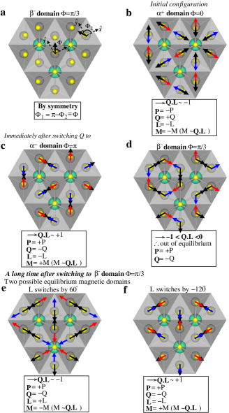
The trilinear coupling of Eq. 47 is quite remarkable. It implies that in the A2 phase the trimer distortion not only induces a polarization but also mediates a non-trivial bulk P-M coupling. To make this clear, we consider a thought experiment in which an electric field, 𝐄𝐄\mathbf{E} applied along the z𝑧z axis can switch P to any one of the three trimer domains with PP-\textbf{P} (more in the Discussion). Let the system be initially in the α+superscript𝛼\alpha^{+} domain with polarization +PP+\textbf{P} and 𝐐α𝐋α=1subscript𝐐𝛼subscript𝐋𝛼1{\mathbf{Q}}_{\alpha}\cdot{\mathbf{L}}_{\alpha}=-1, Fig. 7b. Then there are two possible scenarios:

{α+αsuperscript𝛼superscript𝛼\alpha^{+}\rightarrow\alpha^{-}}. In a proper FE like PbTiO3 the structure of the +PP+\textbf{P} domain is related to the PP-\textbf{P} domain by a reversal in the direction of the polar distortions w.r.t the PE structure, e.g, the Ti4+ ion moving from up to down. The analogous situation in the hexa systems corresponds to a structural change from a 2-up/1-down buckling and tilting ‘out’ of the R-planes and bypyramids, respectively, to a 1-up/2-down and tilting ‘in’, while remaining in the same distinct domain, e.g., α+superscript𝛼\alpha^{+}. This corresponds to switching P via rotating ΦΦ\Phi by π𝜋\pi (Fig. 7c). In this αsuperscript𝛼\alpha^{-} domain, because of Eq. 47, either 𝐋αsubscript𝐋𝛼\mathbf{L}_{\alpha} has to rotate 180 (𝐐α𝐋α=1subscript𝐐𝛼subscript𝐋𝛼1{\mathbf{Q}}_{\alpha}\cdot{\mathbf{L}}_{\alpha}=-1) or the small canting angle has to change sign (𝐐α𝐋α=+1subscript𝐐𝛼subscript𝐋𝛼1{\mathbf{Q}}_{\alpha}\cdot{\mathbf{L}}_{\alpha}=+1). It is not unreasonable to expect the latter to be more favorable, leading to a reversal of M.

{α+βsuperscript𝛼superscript𝛽\alpha^{+}\rightarrow\beta^{-}}. The improper nature of ferroelectricity, however, offers an even more interesting possibility is that there exists three distinct and accessible domains (α𝛼\alpha, β𝛽\beta, and γ𝛾\gamma). As an example let P switch via rotating ΦΦ\Phi by π/3𝜋3\pi/3 and consider the configuration immediately after, Fig. 7d. In this βsuperscript𝛽\beta^{-} domain 1<𝐐α𝐋α<01subscript𝐐𝛼subscript𝐋𝛼0-1<{\mathbf{Q}}_{\alpha}\cdot{\mathbf{L}}_{\alpha}<0, implying the system is not in equilibrium, and therefore 𝐋αsubscript𝐋𝛼\mathbf{L}_{\alpha} must rotate by either |π/3|𝜋3|\pi/3|, Fig. 7e, or |2π/3|2𝜋3|2\pi/3|, Fig. 7f. In the former case 𝐐α𝐋α=1subscript𝐐𝛼subscript𝐋𝛼1{\mathbf{Q}}_{\alpha}\cdot{\mathbf{L}}_{\alpha}=-1 as in the initial α+superscript𝛼\alpha^{+} configuration, therefore M is not reversed, while in the latter 𝐐α𝐋α=+1subscript𝐐𝛼subscript𝐋𝛼1{\mathbf{Q}}_{\alpha}\cdot{\mathbf{L}}_{\alpha}=+1 and M switches 180.

VII.5 Discussion: Possible realizations of predictions

Realization 1: The hexagonal Manganites: Fig. 8 shows Piezoelectric force microscopy (PFM) and Magnetoelectric force microscopy (MeFM) images. The MeFM images, were aligned to PFM image by the topographic landmarks and are in the same color scale, 9.18 mHz.

Refer to caption
Figure 8: Magnetoelectric force microscopy (MeFM) images. a Piezoelectric force microscopy (PFM) image taken under ambient condition. b and c, show MeFM images taken under the application of 6 and 0.2 T external magnetic field, respectively.

Realization 2: The A2 ground state in hexa RFeO3:

VII.5.1 Origin of ferroelectricity in hexaferrites

Experimental studies of hexagonal ferrites RFeO3 indicates that at room temperature these materials have a polar P63cm structure Bossak et al. (2004); Magome et al. (2010) while at high temperature they crystallize in the paraelectric P63/mmc phase Jeong et al. (2012a).According to the group theory analysis there are three possible phase transition sequences connecting the high-temperature phase with the low-temperature P63cm phase Fennie and Rabe (2005): (1) a direct transition between the two phases by freezing-in a K3 zone boundary phonon mode, (2) a transition to the intermediate P63mc ferroelectric phase by softening of the Γ2subscriptsuperscriptΓ2\Gamma^{-}_{2} zone-center polar mode followed by the transition to the low-temperature phase, and (3) a transition to the intermediate non-polar P63/mcm phase by freezing-in a zone boundary K1 mode followed by transition to the low temperature phase.

Table 3: Calculated frequencies of relevant phonon modes for the high-temperature phase of RTMO3 (TM=Fe, Mn). In addition, electric polarization (P𝑃P) for the fully relaxed low-temperature structures are listed.
System ω𝜔\omega (cm-1) Pssubscript𝑃𝑠P_{s}
Γ21superscriptsubscriptΓ21\Gamma_{2}^{-1} K1 K3 (μ𝜇\muC/cm2)
HoFeO3 73 276 114i 9.0
ErFeO3 75 271 113i 9.2
TmFeO3 78 268 112i 9.5
YbFeO3 102 298 97i 9.6
LuFeO3 84 263 108i 9.8
HoMnO3 65 249 125i 6.9
ErMnO3 61 245 128i 7.0
TmMnO3 56 240 130i 7.2
YbFeO3 92 266 127i 7.4
LuFeO3 54 232 132i 7.4

Calculated phonon frequencies in the high-temperature phase for the above mentioned phonon modes are presented in Table. 3 both for manganites and ferrites with different R ions. As seen, for all compounds the K3 phonon mode is unstable while both Γ2subscriptsuperscriptΓ2\Gamma^{-}_{2} and K1 modes are stable. These results indicate that for ferrites systems, similarly as for manganites, the high-temperature P63/mmc phase transforms directly into the low-temperature P63cm structure by softening of the K3 zone boundary mode. The non-linear coupling between K3 and the polar Γ2subscriptsuperscriptΓ2\Gamma^{-}_{2} mode induces polarization into the system. The polarization is thus a secondary order parameter and the ferroelectricity is improper. Indeed, for a high-temperature structure with frozen-in K3 mode the calculated polarization is very small (less than 0.1 μ𝜇\muC/cm2) and originates only from an electronic contribution. Only when full ionic relaxations are done the polarization of the order of 10 μ𝜇\muC/cm2 develops (see Table. 3).

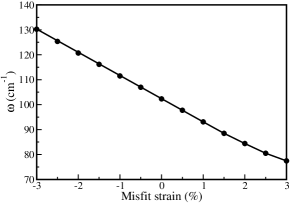
The above analysis indicates that the origin of ferroelectricity in RFeO3 is the same as in manganites. Therefore, an intermediate P63mc phase which was proposed to explain the two-step polarization decay observed for YbFeO3 Jeong et al. (2012b) is rather unlikely. Indeed, the presence of such intermediate phase would typically lead to soft Γ2subscriptsuperscriptΓ2\Gamma^{-}_{2} mode which is not the case according to our calculations. In fact, we found that if we freeze-in the Γ2subscriptsuperscriptΓ2\Gamma^{-}_{2} mode and perform full structural relaxations, the amplitude of the mode goes to zero. We also found that the Γ2subscriptsuperscriptΓ2\Gamma^{-}_{2} mode remains stable for a wide range of epitaxial strain, see Fig. 9.

Refer to caption
Figure 9: Effect of epitaxial strain. Calculated phonon frequency of Γ2subscriptsuperscriptΓ2\Gamma^{-}_{2} mode as a function of epitaxial strain.

VII.5.2 Non-collinear magnetic spin configurations

We have considered 8 non-collinear magnetic configurations, as depicted in Fig. 10, to determine the magnetic ground state of the hexagonal manganite and ferrite systems.

Refer to caption
Figure 10: Non-collinear magnetic structures. 120 spin ordering with spin directions directed by blue arrows. Light and dark gray balls represent magnetic TM ions situated at layer I and II, respectively. The angles Ψ1subscriptΨ1\Psi_{1} and Ψ2subscriptΨ2\Psi_{2} define non-collinear spin configurations. The values of angles [Ψ1,Ψ2]subscriptΨ1subscriptΨ2[\Psi_{1},\Psi_{2}] in Φ=0Φ0\Phi=0 structural domain are given. Principle magnetic structures, those are compatible with the crystal symmetry, are denoted as A1, A2, B1 and B2. Among four principle magnetic structures A2 allows weak ferromagnetism (wFM). The intermediate states that connect A2 with A1 and B2, denoted as A and I2, respectively, also allow wFM.

VII.5.3 Symmetric exchange interaction Determine the magnetic configuration

Refer to caption
Figure 11: Symmetric exchange paths a Symmetric exchange paths in paraelectric phase of Jnnsubscript𝐽𝑛𝑛J_{nn}, Jc1superscriptsubscript𝐽𝑐1J_{c}^{1} and Jc2superscriptsubscript𝐽𝑐2J_{c}^{2} are denoted by solid black, cyan and pink lines, respectively. b The trimer distortion splits six fold degenerate nn exchange interaction Jnnsubscript𝐽𝑛𝑛J_{nn} into two fold degenerate Jnn1superscriptsubscript𝐽𝑛𝑛1J_{nn}^{1} (mediated via TM-O1psuperscriptsubscriptabsent𝑝1{}_{p}^{1}-TM exchange path) and four fold degenerate Jnn2superscriptsubscript𝐽𝑛𝑛2J_{nn}^{2} (mediated via TM-O2psuperscriptsubscriptabsent𝑝2{}_{p}^{2}-TM exchange path). As the nn exchange interactions are of superexchange in nature and the in-plane distortions in terms of bond lengths and bond angles are not significant, we considered Jnn1superscriptsubscript𝐽𝑛𝑛1J_{nn}^{1}=Jnn2superscriptsubscript𝐽𝑛𝑛2J_{nn}^{2}=Jnnsubscript𝐽𝑛𝑛J_{nn}. Similarly trimer distortion splits six fold degenerate inter-layer exchange interactions Jc1superscriptsubscript𝐽𝑐1J_{c}^{1} (Jc2superscriptsubscript𝐽𝑐2J_{c}^{2}) into two fold degenerate Jc11superscriptsubscript𝐽𝑐11J_{c}^{11} (Jc21superscriptsubscript𝐽𝑐21J_{c}^{21}) and four fold degenerate Jc12superscriptsubscript𝐽𝑐12J_{c}^{12} (Jc22superscriptsubscript𝐽𝑐22J_{c}^{22}), respectively. While Jc11superscriptsubscript𝐽𝑐11J_{c}^{11} is mediated by two equivalent X-O-Lu1-O-X exchange pathways, Jc12superscriptsubscript𝐽𝑐12J_{c}^{12} interaction is mediated by one X-O-Lu1-O-X and one X-O-Lu2-O-X exchange pathways. Jc21superscriptsubscript𝐽𝑐21J_{c}^{21} and Jc22superscriptsubscript𝐽𝑐22J_{c}^{22} are mediated via X-O-Lu1-O-X and X-O-Lu2-O-X exchange pathways, respectively.
Table 4: Exchange parameters and the corresponding Curie-Weiss temperatures (ΘCWsubscriptΘ𝐶𝑊\Theta_{CW}) for LFO and LMO. In the last row (LMO-II) the exchange parameters obtained for LMO using the lattice parameters of LFO are given.
System Jnnsubscript𝐽𝑛𝑛J_{nn} Jnnnsubscript𝐽𝑛𝑛𝑛J_{nnn} Jc11superscriptsubscript𝐽𝑐11J_{c}^{11} Jc12superscriptsubscript𝐽𝑐12J_{c}^{12} Jc21superscriptsubscript𝐽𝑐21J_{c}^{21} Jc22superscriptsubscript𝐽𝑐22J_{c}^{22} ΘCWsubscriptΘ𝐶𝑊\Theta_{CW}
meV meV meV meV meV meV K
LFO 6.307 0.457 0.942 0.557 0.088 0.044 1525
LMO 2.573 -0.254 -0.369 -0.322 -0.152 0.050 274
LMO-II 3.152 -0.452 -0.730 -0.687 -0.417 0.113

We considered in-plane nearest neighbor (nn), Jnnsubscript𝐽𝑛𝑛J_{nn}, and next-nearest neighbor (nnn), Jnnnsubscript𝐽𝑛𝑛𝑛J_{nnn}, exchange interactions as well as two different inter-layer interactions (Jc1superscriptsubscript𝐽𝑐1J_{c}^{1} and Jc2superscriptsubscript𝐽𝑐2J_{c}^{2}), see Fig. 11. While in the ferroelectric phase Jnnsubscript𝐽𝑛𝑛J_{nn} splits into two nonequivalent exchange interactions, the difference between them is very small and therefore this effect was neglected. The same applies to Jnnnsubscript𝐽𝑛𝑛𝑛J_{nnn}. Similarly, Jc1superscriptsubscript𝐽𝑐1J_{c}^{1} (Jc2superscriptsubscript𝐽𝑐2J_{c}^{2}) splits into Jc11superscriptsubscript𝐽𝑐11J_{c}^{11} and Jc12superscriptsubscript𝐽𝑐12J_{c}^{12} (Jc21superscriptsubscript𝐽𝑐21J_{c}^{21} and Jc22superscriptsubscript𝐽𝑐22J_{c}^{22}) interactions. In this case, however, this splitting is essential for determination of the magnetic ground state and therefore it was included. The exchange interactions were calculated by fitting ab initio energies of several collinear magnetic configurations. The results are presented in Table 4.

As seen, Jnnnsubscript𝐽𝑛𝑛𝑛J_{nnn} is order of magnitude smaller than Jnnsubscript𝐽𝑛𝑛J_{nn} and has a negligible influence on magnetic ordering. Therefore, it was neglected in the main manuscript. On the other hand, Jc2superscriptsubscript𝐽𝑐2J_{c}^{2} is not always significantly smaller than Jc1superscriptsubscript𝐽𝑐1J_{c}^{1}. Nevertheless, its qualitative effect is quite analogous to Jc1superscriptsubscript𝐽𝑐1J_{c}^{1} and therefore for clarity it was not included in the main text. Here, however, this interaction is included on equal footing with Jc1superscriptsubscript𝐽𝑐1J_{c}^{1}.

The dominant exchange parameter is Jnnsubscript𝐽𝑛𝑛J_{nn}. It is the AFM superexchange interaction mediated by equatorial oxygens, Oeq. For LFO this exchange originates primarily from the hopping from O 2p𝑝p states into minority Fe 3d𝑑d states. Since the TM-Oeq-TM angle is 120 the FM superexchange involving two perpendicular p𝑝p orbitals is expected to be much smaller than the AFM superexchange involving a single orbital. This mechanism is also present for LMO but here the hopping from occupied into empty 3d𝑑d orbitals is equally important. In the latter case the dominant in-plane hoppings are between esuperscript𝑒e^{\prime} and e′′superscript𝑒′′e^{\prime\prime} orbitals which favor antiparallel spins. As a result Jnnsubscript𝐽𝑛𝑛J_{nn} for LMO is also AFM. The magnitude of Jnnsubscript𝐽𝑛𝑛J_{nn} is smaller for LMO. This is partially caused by a larger band gap for this compound as compared to LFO. However, probably more important contribution comes from the hopping from occupied 3d𝑑d orbitals into empty majority d3z2subscript𝑑3superscript𝑧2d_{3z^{2}} states that mediates a FM coupling and partially compensates the AFM contribution. Therefore, ferrites are expected to have in general larger Jnnsubscript𝐽𝑛𝑛J_{nn} than manganites which indicates that magnetic ordering temperature in ferrites should be much higher; possibly close to the room temperature.

As seen from Table. 4, for LFO the inter-layer exchange parameters are AFM. This can be understood by noting that both exchange parameters originates primarily from virtual hopping of two pzsubscript𝑝𝑧p_{z} electrons of Oap ion into 3d𝑑d minority states of Fe and 5d𝑑d orbitals of R. These hoppings are the most effective for both apical oxygens in the exchange path only when spins on Fe ions are antiparallel. Otherwise, pzsubscript𝑝𝑧p_{z} electrons from different Oap ions cannot hop on the same orbital of the R ion. The above mechanism of AFM interlayer coupling is also present for LMO. In this case however, similarly as for in-plane exchange interactions, there is another type of low-energy excitations that can contribute to the interlayer exchange coupling. They involve hopping from occupied 3d𝑑d Mn states into empty 3d𝑑d states of Mn ion in the adjacent plane (note that this hopping is still mediated by Oap and R ions on the exchange path). Clearly, the most important hopping in this case is between filled majority esuperscript𝑒e^{\prime} and empty majority d3z2subscript𝑑3superscript𝑧2d_{3z^{2}} which prefers parallel spins. This leads to FM coupling which competes with AFM exchange interaction from the above paragraph. As a result either sign of interlayer exchange couplings is expected for LMO.

Importantly, we find that |Jck1|>|Jck2|superscriptsubscript𝐽𝑐𝑘1superscriptsubscript𝐽𝑐𝑘2|J_{c}^{k1}|>|J_{c}^{k2}| (k=1,2𝑘12k=1,2) both for LMO and LFO. In fact this is a generic feature for these systems. Indeed, consider three different nn inter-layer interactions: J12subscript𝐽12J_{12}, J14subscript𝐽14J_{14}, and J16subscript𝐽16J_{16} (see Fig. 11 for notation). In the paraelectric phase they are all equal to Jc1superscriptsubscript𝐽𝑐1J_{c}^{1} and their change under the trimer distortion can be written in the following way (up to second order in QK3subscript𝑄subscript𝐾3Q_{K_{3}}):

J1jJc1+(J1jQI)0QI+(J1jQI)0Q1+(2J1jQI2)0QI2+(2J1j(QI)2)0(QI)2+(2J1jQIQI)0QIQIsubscript𝐽1𝑗superscriptsubscript𝐽𝑐1subscriptsubscript𝐽1𝑗subscript𝑄I0subscript𝑄Isubscriptsubscript𝐽1𝑗subscriptsuperscript𝑄𝐼0subscriptsuperscript𝑄1subscriptsuperscript2subscript𝐽1𝑗superscriptsubscript𝑄I20superscriptsubscript𝑄I2subscriptsuperscript2subscript𝐽1𝑗superscriptsuperscriptsubscript𝑄I20superscriptsuperscriptsubscript𝑄I2subscriptsuperscript2subscript𝐽1𝑗subscript𝑄Isuperscriptsubscript𝑄I0subscript𝑄Isuperscriptsubscript𝑄IJ_{1j}\approx J_{c}^{1}+\left(\frac{\partial J_{1j}}{\partial Q_{\rm I}}\right)_{0}Q_{\rm I}+\left(\frac{\partial J_{1j}}{\partial Q^{*}_{I}}\right)_{0}Q^{*}_{1}+\left(\frac{\partial^{2}J_{1j}}{\partial Q_{\rm I}^{2}}\right)_{0}Q_{\rm I}^{2}+\left(\frac{\partial^{2}J_{1j}}{\partial(Q_{\rm I}^{*})^{2}}\right)_{0}(Q_{\rm I}^{*})^{2}+\left(\frac{\partial^{2}J_{1j}}{\partial Q_{\rm I}\partial Q_{\rm I}^{*}}\right)_{0}Q_{\rm I}Q_{\rm I}^{*} (63)

where j=2,4,6𝑗246j=2,4,6, subscript 00 indicates that the derivatives must be evaluated in the paraelectric phase, and order parameters QIsubscript𝑄IQ_{\rm I}, QIsuperscriptsubscript𝑄IQ_{\rm I}^{*} were introduced in the previous section. Note that the derivatives must be invariant under the symmetry operations of the paraelectric phase. In particular, this condition requires first order derivatives to be zero and the mixed second order derivatives to be independent on index j𝑗j. Further it imposes relations between remaining second order derivatives such that we can write

J12Jc1+cQK32+2Xcos(2Φ)QK32subscript𝐽12superscriptsubscript𝐽𝑐1𝑐superscriptsubscript𝑄subscript𝐾322𝑋2Φsuperscriptsubscript𝑄subscript𝐾32\displaystyle J_{12}\approx J_{c}^{1}+cQ_{K_{3}}^{2}+2X\cos(2\Phi)Q_{K_{3}}^{2} (64)
J14Jc1+cQK32+2Xcos(2Φ+2π/3)QK32subscript𝐽14superscriptsubscript𝐽𝑐1𝑐superscriptsubscript𝑄subscript𝐾322𝑋2Φ2𝜋3superscriptsubscript𝑄subscript𝐾32\displaystyle J_{14}\approx J_{c}^{1}+cQ_{K_{3}}^{2}+2X\cos(2\Phi+2\pi/3)Q_{K_{3}}^{2} (65)
J16Jc1+cQK32+2Xcos(2Φ2π/3)QK32subscript𝐽16superscriptsubscript𝐽𝑐1𝑐superscriptsubscript𝑄subscript𝐾322𝑋2Φ2𝜋3superscriptsubscript𝑄subscript𝐾32\displaystyle J_{16}\approx J_{c}^{1}+cQ_{K_{3}}^{2}+2X\cos(2\Phi-2\pi/3)Q_{K_{3}}^{2} (66)

where c𝑐c is a constant and X=(2J12QI2)0𝑋subscriptsuperscript2subscript𝐽12superscriptsubscript𝑄I20X=\left(\frac{\partial^{2}J_{12}}{\partial Q_{\rm I}^{2}}\right)_{0}. In the α𝛼\alpha (Φ=0Φ0\Phi=0) phase we have

J12=Jc11Jc1+cQK32+2XQK32subscript𝐽12superscriptsubscript𝐽𝑐11superscriptsubscript𝐽𝑐1𝑐superscriptsubscript𝑄subscript𝐾322𝑋superscriptsubscript𝑄subscript𝐾32\displaystyle J_{12}=J_{c}^{11}\approx J_{c}^{1}+cQ_{K_{3}}^{2}+2XQ_{K_{3}}^{2} (67)
J14=J16=Jc12Jc1+cQK32XQK32subscript𝐽14subscript𝐽16superscriptsubscript𝐽𝑐12superscriptsubscript𝐽𝑐1𝑐superscriptsubscript𝑄subscript𝐾32𝑋superscriptsubscript𝑄subscript𝐾32\displaystyle J_{14}=J_{16}=J_{c}^{12}\approx J_{c}^{1}+cQ_{K_{3}}^{2}-XQ_{K_{3}}^{2} (68)

It is reasonable to assume that X𝑋X has the same sign as Jc1superscriptsubscript𝐽𝑐1J_{c}^{1} which leads to |Jc11|>|Jc12|superscriptsubscript𝐽𝑐11superscriptsubscript𝐽𝑐12|J_{c}^{11}|>|J_{c}^{12}|. Using similar consideration we can also prove that |Jc21|>|Jc22|superscriptsubscript𝐽𝑐21superscriptsubscript𝐽𝑐22|J_{c}^{21}|>|J_{c}^{22}|.

VII.5.4 DM

Table 5: Magnitudes of z𝑧z and xy𝑥𝑦xy components of nn DM interactions as well as components of SIA tensor for LFO and LMO compounds. Dz0subscriptsuperscript𝐷0𝑧D^{0}_{z} is the magnitude of the z𝑧z component of DM vector in the paraelectric phase while Dzsubscript𝐷𝑧D_{z} (Dxysubscript𝐷𝑥𝑦D_{xy}) and Dzsubscriptsuperscript𝐷𝑧D^{\prime}_{z} (Dxysubscriptsuperscript𝐷𝑥𝑦D^{\prime}_{xy}) are magnitudes of the z𝑧z (xy𝑥𝑦xy) components of DM vectors in the ferroelectric phase mediated by TM-Op1subscriptsuperscriptabsent1𝑝{}^{1}_{p}-TM and TM-Op2subscriptsuperscriptabsent2𝑝{}^{2}_{p}-TM paths, respectively. Notation for components of the SIA tensor is given in the text. Unite are meV.
System Dxysubscript𝐷𝑥𝑦D_{xy} Dxysubscriptsuperscript𝐷𝑥𝑦D^{\prime}_{xy} Dzsubscript𝐷𝑧D_{z} Dzsubscriptsuperscript𝐷𝑧D^{\prime}_{z} Dz0superscriptsubscript𝐷𝑧0D_{z}^{0} τxxsubscript𝜏𝑥𝑥\tau_{xx} τyysubscript𝜏𝑦𝑦\tau_{yy} τzzsubscript𝜏𝑧𝑧\tau_{zz} τxzsubscript𝜏𝑥𝑧\tau_{xz} τzz0subscriptsuperscript𝜏0𝑧𝑧\tau^{0}_{zz}
LFO 0.095 0.097 0.061 0.047 0.072 0.081 0.083 -0.164 0.018 0.181
LMO -0.047 -0.050 0.027 0.033 0.042 -0.077 -0.079 0.156 -0.013 -0.160

We calculated all six DM interactions acting on TM 1 ion (see Fig. 5 for notation). We considered a 3×3×1331\surd 3\times\surd 3\times 1 supercell with 18 RXO3 (X=Mn,Fe) formula units and followed the procedure described in Ref.Eric12 . This procedure is described as: (1) select one particular interaction by replacing selected X+3 ions with Al3+{}^{+}3 ions, (2) do total energy calculation by constraining the direction of the spin moments. The z𝑧z component of the DM interaction between ith and jth TM ions is then given by,

Dijz=1S2(E[S^xi,S^yj]E[S^xi,S^yj])superscriptsubscript𝐷𝑖𝑗𝑧1superscript𝑆2𝐸superscriptsubscript^𝑆𝑥𝑖superscriptsubscript^𝑆𝑦𝑗𝐸superscriptsubscript^𝑆𝑥𝑖superscriptsubscript^𝑆𝑦𝑗D_{ij}^{z}=\dfrac{1}{S^{2}}(E[\hat{S}_{x}^{i},\hat{S}_{y}^{j}]-E[\hat{S}_{-x}^{i},\hat{S}_{y}^{j}]) (69)

Similarly one can calculate the other components.

In Table 5 we show the calculated magnitudes of z𝑧z and xy𝑥𝑦xy components of both types of DM vectors for LFO and LMO compounds. The directions of the z𝑧z components in the paraelectric phase are shown in Fig. 5. They are the same for both compounds and they are not altered in the ferroelectric phase. The directions of the transverse components for LFO are shown in Fig. 5. For LMO the transverse components are opposite.

VII.5.5 SIA

We evaluated the components of SIA tensor by replacing all TM ions by Al+3 ions except TM 1 and calculating total energy by constraining spin directions along [100], [010], [001] and [101]. The off-diagonal component τxzsubscript𝜏𝑥𝑧\tau_{xz} is given by,

τxz=12S2(2E[S^x,0,S^z]E[S^x,0,0]E[0,0,S^z])subscript𝜏𝑥𝑧12superscript𝑆22𝐸subscript^𝑆𝑥0subscript^𝑆𝑧𝐸subscript^𝑆𝑥00𝐸00subscript^𝑆𝑧\tau_{xz}=\dfrac{1}{2S^{2}}(2E[\hat{S}_{x},0,\hat{S}_{z}]-E[\hat{S}_{x},0,0]-E[0,0,\hat{S}_{z}]) (70)

The diagonal components were determined by solving the following equations,

τxx+E0=1S2E[S^x,0,0]subscript𝜏𝑥𝑥subscript𝐸01superscript𝑆2𝐸subscript^𝑆𝑥00\displaystyle\tau_{xx}+E_{0}=\dfrac{1}{S^{2}}E[\hat{S}_{x},0,0] (71)
τyy+E0=1S2E[0,S^y,0]subscript𝜏𝑦𝑦subscript𝐸01superscript𝑆2𝐸0subscript^𝑆𝑦0\displaystyle\tau_{yy}+E_{0}=\dfrac{1}{S^{2}}E[0,\hat{S}_{y},0] (72)
τzz+E0=1S2E[0,0,S^z]subscript𝜏𝑧𝑧subscript𝐸01superscript𝑆2𝐸00subscript^𝑆𝑧\displaystyle\tau_{zz}+E_{0}=\dfrac{1}{S^{2}}E[0,0,\hat{S}_{z}] (73)
τxx+τyy+τzz=0subscript𝜏𝑥𝑥subscript𝜏𝑦𝑦subscript𝜏𝑧𝑧0\displaystyle\tau_{xx}+\tau_{yy}+\tau_{zz}=0 (74)

where E0subscript𝐸0E_{0} is the total energy without any spin-spin interactions.

Calculated components of SIA tensor in Eq. (36) are shown in Table 5. The most important component is τzzsuperscript𝜏𝑧𝑧\tau^{zz} which is positive for LMO and negative for LFO. Different signs of τzzsuperscript𝜏𝑧𝑧\tau^{zz} for these materials stems from different number of 3d𝑑d electrons for these materials. Indeed, in the second order perturbation theory the energy decrease due to SOC can be written as ΔE=nmλ2|m|𝐬^𝐥^|nϵmϵn\Delta E=-\sum_{n\neq m}\lambda^{2}\frac{|\langle m|\mathbf{\hat{s}}\cdot\mathbf{\hat{l}}|n\rangle}{\epsilon_{m}-\epsilon_{n}}. Here |nket𝑛|n\rangle and |mket𝑚|m\rangle are, respectively, occupied and empty single-electron eigenstates of 3d𝑑d character with ϵnsubscriptitalic-ϵ𝑛\epsilon_{n} and ϵmsubscriptitalic-ϵ𝑚\epsilon_{m} being the corresponding eigenenergies, λ𝜆\lambda is the SOC constant, and 𝐬^^𝐬\mathbf{\hat{s}} (𝐥^^𝐥\mathbf{\hat{l}}) is single-electron spin (orbital) angular momentum operator. We choose 𝐥^^𝐥\mathbf{\hat{l}} quantization axis along z𝑧z. For LFO with half-filled 3d𝑑d shell we have only spin-flip excitations which are induced by a transverse component of 𝐬^^𝐬\mathbf{\hat{s}}. In addition, the most important excitations (corresponding to the smallest energy denominators) involve also the change of the magnetic orbital quantum number, Δml=±1Δsubscript𝑚𝑙plus-or-minus1\Delta m_{l}=\pm 1 which requires a transverse component of 𝐥^^𝐥\mathbf{\hat{l}}. Therefore, the largest energy gain is achieved when 𝐬^^𝐬\mathbf{\hat{s}} and 𝐥^^𝐥\mathbf{\hat{l}} are parallel (so that their transverse components couple with each other) preferring spins along z𝑧z axis and leading to τzz<0superscript𝜏𝑧𝑧0\tau^{zz}<0. On the other hand, for LMO the most important excitation is the transition from majority esuperscript𝑒e^{\prime} to majority d3z2subscript𝑑3superscript𝑧2d_{3z^{2}}. Here spin is conserved but the magnetic orbital quantum number changes which is possible only when 𝐬^^𝐬\mathbf{\hat{s}} and 𝐥^^𝐥\mathbf{\hat{l}} are perpendicular to each other, i.e., when spins lie in the xy𝑥𝑦xy plane leading to τzz>0superscript𝜏𝑧𝑧0\tau^{zz}>0.

References

  • Bousquet et al. (2008) E. Bousquet, M. Dawber, N. Stucki, C. Lichtensteiger, P. Hermet, S. Gariglio, J.-M. Triscone, and Ph. Ghosez, Nature 452, 732 (2008).
  • Tokunaga et al. (2009) Y. Tokunaga, N. Furukawa, H. Sakai, Y. Taguchi, T.-h. Arima, and Y. Tokura, Nat Mater 8, 558 (2009).
  • Lee et al. (2010) J. H. Lee, L. Fang, E. Vlahos, X. Ke, Y. W. Jung, L. F. Kourkoutis, J.-W. Kim, P. J. Ryan, T. Heeg, M. Roeckerath, et al., Nature 466, 954 (2010).
  • Tokunaga et al. (2012) Y. Tokunaga, Y. Taguchi, T.-h. Arima, and Y. Tokura, Nat Phys 8, 838 (2012).
  • Mermin (1979) N. D. Mermin, Rev. Mod. Phys. 51, 591 (1979).
  • Balke et al. (2012) N. Balke, B. Winchester, W. Ren, Y. H. Chu, A. N. Morozovska, E. A. Eliseev, M. Huijben, R. K. Vasudevan, P. Maksymovych, J. Britson, et al., Nat Phys 8, 81 (2012).
  • Meier et al. (2012) D. Meier, J. Seidel, A. Cano, K. Delaney, Y. Kumagai, M. Mostovoy, N. A. Spaldin, R. Ramesh, and M. Fiebig, Nature Materials 11, 284 (2012).
  • Tagantsev and Sonin (1989) A. K. Tagantsev and E. B. Sonin, Ferroelectrics 98, 297 (1989).
  • Ramesh and Spaldin (2007) R. Ramesh and N. A. Spaldin, Nat Mater 6, 21 (2007).
  • Cheong and Mostovoy (2007) S.-W. Cheong and M. Mostovoy, Nat Mater 6, 13 (2007).
  • Choi et al. (2010) T. Choi, Y. Horibe, H. T. Yi, Y. J. Choi, W. Wu, and S. W. Cheong, Nat Mater 9, 253 (2010).
  • Chae et al. (2010) S. C. Chae, Y. Horibe, D. Y. Jeong, S. Rodan, N. Lee, and S. W. Cheong, Proceedings of the National Academy of Sciences 107, 21366 (2010).
  • Mostovoy (2010) M. Mostovoy, Nat Mater 9, 188 (2010).
  • Kumagai and Spaldin (2013) Y. Kumagai and N. A. Spaldin, Nat Commun 4 (2013).
  • Geng et al. (2012) Y. Geng, N. Lee, Y. J. Choi, S.-W. Cheong, and W. Wu, Nano Letters 12, 6055 (2012).
  • Artyukhin et al. (2012) S. Artyukhin, K. T. Delaney, N. A. Spaldin, and M. Mostovoy, ArXiv e-prints (2012), eprint 1204.4126.
  • Van Aken et al. (2004) B. B. Van Aken, T. T. M. Palstra, A. Filippetti, and N. A. Spaldin, Nat Mater 3, 164 (2004).
  • Fennie and Rabe (2005) C. J. Fennie and K. M. Rabe, Phys. Rev. B 72, 100103 (2005).
  • Bossak et al. (2004) A. A. Bossak, I. E. Graboy, O. Y. Gorbenko, A. R. Kaul, M. S. Kartavtseva, V. L. Svetchnikov, and H. W. Zandbergen, Chemistry of Materials 16, 1751 (2004).
  • Magome et al. (2010) E. Magome, C. Moriyoshi, Y. Kuroiwa, A. Masuno, and H. Inoue, Japanese Journal of Applied Physics 49, 09ME06 (2010).
  • Wang et al. (2013) W. Wang, J. Zhao, W. Wang, Z. Gai, N. Balke, M. Chi, H. N. Lee, W. Tian, L. Zhu, X. Cheng, et al., Phys. Rev. Lett. 110, 237601 (2013).
  • Fiebig et al. (2003) M. Fiebig, T. Lottermoser, and R. V. Pisarev, Journal of Applied Physics 93, 8194 (2003).
  • Dzyaloshinskii (1957) I. E. Dzyaloshinskii, Sov. Phys. JETP 5, 1259 (1957).
  • Moriya (1960) T. Moriya, Phys. Rev. 120, 91 (1960).
  • Solovyev et al. (2012) I. V. Solovyev, M. V. Valentyuk, and V. V. Mazurenko, Phys. Rev. B 86, 054407 (2012).
  • Jeong et al. (2012a) Y. K. Jeong, J.-H. Lee, S.-J. Ahn, and H. M. Jang, Chemistry of Materials 24, 2426 (2012a).
  • Jeong et al. (2012b) Y. K. Jeong, J.-H. Lee, S.-J. Ahn, S.-W. Song, H. M. Jang, H. Choi, and J. F. Scott, Journal of the American Chemical Society 134, 1450 (2012b).
  • Akbashev et al. (2011) A. R. Akbashev, A. S. Semisalova, N. S. Perov, and A. R. Kaul, Applied Physics Letters 99, 122502 (pages 3) (2011).
  • Fiebig et al. (2000) M. Fiebig, D. Fröhlich, K. Kohn, S. Leute, T. Lottermoser, V. V. Pavlov, and R. V. Pisarev, Phys. Rev. Lett. 84, 5620 (2000).
  • (30) For LMO ΘCWsubscriptΘ𝐶𝑊\Theta_{CW} is strongly underestimated as compared with experimental value of 510 K. This indicates that the value of U=4.5𝑈4.5U=4.5 eV is too large for LMO. Repeating the calculations for smaller values U𝑈U we reached a reasonable agreement with experiment for U=2𝑈2U=2 eV.
  • Anisimov et al. (1997) V. I. Anisimov, F. Aryasetiawan, and A. I. Lichtenstein, Journal of Physics: Condensed Matter 9, 767 (1997).
  • Perdew et al. (1996) J. P. Perdew, K. Burke, and M. Ernzerhof, Phys. Rev. Lett. 77, 3865 (1996).
  • Kresse, G. and Hafner, J. (1993) Kresse, G. and Hafner, J. , Phys. Rev. B 47, 558 (1993).
  • Kresse, G. and Furthmüller, J. (1996) Kresse, G. and Furthmüller, J. , Phys. Rev. B 54, 11169 (1996).
  • (35) P. Blaha, K. Schwartz, G. K. H. Madsen, D. Kvasnicka, and J. Luitz, wIEN2K, An Augmented Plane Wave + Local Orbitals Program for Calculating Crystal Properties, edited by K. Schwarz (Technische Universitatâ Wien, Vienna, 2001).
  • (36) C. Weingart, N. Spaldin, E. Bousquet, Phys. Rev. B 86, 094413 (2012).

Acknowledgments. We acknowledge discussions with D.G. Schlom, Julia Mundy, Charles Brooks, P. Schiffer, Maxim Mostovoy, and J.Moyer. This work started at the suggestion of D.G.S. and J.M. H.D. and C.J.F. were supported by the DOE-BES under Award Number DE-SCOO02334. A.L.W. was supported by the Cornell Center for Materials Research with funding from NSF MRSEC program, cooperative agreement DMR-1120296. Y.G. and W.W. were supported by the U.S. DOE-BES under Award Number DE-SC0008147.