Magnetization dynamics in Co2MnGe/Al2O3/Co tunnel junctions grown on different substrates
Abstract
We study static and dynamic magnetic properties of Co2MnGe (13 nm)/Al2O3 (3 nm)/Co (13 nm) tunnel magnetic junctions (TMJ), deposited on various single crystalline substrates (a-plane sapphire, MgO(100), Si(111)). The results are compared to the magnetic properties of Co and of Co2MnGe single films lying on sapphire substrates. X-rays diffraction always shows a (110) orientation of the Co2MnGe films. Structural observations obtained by high resolution transmission electron microscopy confirmed the high quality of the TMJ grown on sapphire. Our vibrating sample magnetometry measurements reveal in-plane anisotropy only in samples grown on a sapphire substrate. Depending on the substrate, the ferromagnetic resonance spectra of the TMJs, studied by the microstrip technique, show one or two pseudo-uniform modes. In the case of MgO and of Si substrates only one mode is observed: it is described by magnetic parameters (g-factor, effective magnetization, in-plane magnetic anisotropy) derived in the frame of a simple expression of the magnetic energy density; these parameters are practically identical to those obtained for the Co single film. With a sapphire substrate two modes are present: one of them does not appreciably differ from the observed mode in the Co single film while the other one is similar to the mode appearing in the Co2MnGe single film: their magnetic parameters can thus be determined independently, using a classical model for the energy density in the absence of interlayer exchange coupling.
I Introduction
Tunnel magnetic junctions (TMJ) are of great interest due to their use in magnetic memory (MRAM) [1], in low field magnetic sensors [2] and in microwave components for spintronics [3]. The tunnel magnetoresistance (TMR) is very sensitive to the spin polarization of the magnetic electrodes of TMJs and therefore, a highly spin-polarized current source is strongly desired. A promising method for this purpose is the use of half-metallic ferromagnets, which exhibit a half metallic behavior with a gap separating two energy bands of opposite spin directions, thus providing for a 100 spin polarization. Therefore, due to their half-metallicity and to their high Curie temperature, Co-based Heusler alloys are now used as electrodes in TMJs. Fully epitaxial MTJs consisting of a Co-based full Heusler thin film as a lower electrode, of a MgO tunnel barrier and of a CoFe upper electrode demonstrated TMRs of 42 at room temperature [4]. Moreover, TMRs of up to 220 at room temperature and of 390 at 5K have been measured in magnetic tunnel junctions (MTJs) using Co2FeSi0.5Al0.5 Heusler alloy electrodes [5]. However, up to now, the demonstrated TMR amplitudes using Heusler alloys as magnetic electrodes in MTJs remain lower than those using normal transition metals or their alloys. The quality of MTJs depends strongly on the interfacial roughness, interdiffusion and oxygen content, which in turn depend on the materials used in the stack and on the conditions of deposition and annealing. Therefore, the control of such parameters should enhance the half-metallicity of electrodes and thus increase TMR values. Ferromagnetic resonance (FMR) allows for the investigation of the dynamics of the magnetization of single layers and of multilayers and thus for the determination of coupling parameters and of magnetic anisotropy in relation to the interfacial characteristics. Therefore, FMR and vibrating sample magnetometry have been used for the investigation of static and dynamic magnetic properties Co2MnGe (13 nm)/Al2O3 (3nm)/Co (13 nm) TMJ deposited on a-plane sapphire, MgO and Si substrates.
II Samples
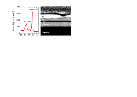
Co2MnGe (13 nm)/Al2O3 (3nm)/Co (13 nm) TMJs have been deposited by RF magnetron sputtering in an ultrahigh vacuum on the following substrates: a-plane sapphire, MgO (100) and Si(111). For comparison, single films of Co2MnGe and Co of the same thickness (13 nm) deposited on sapphire were also grown. All the samples, except the Co single layer, were preliminarily covered with a 4 nm thick vanadium-seed-layer and subsequently overlayered by a 4 nm thick gold layer protecting them against oxidation. A more detailed description of the sample preparation procedure can be found elsewhere [6]. The X-rays pattern (using a Cobalt line source at Å) shown on figure 1a indicates that the Co2MnGe single thin film is (110) oriented. Its deduced lattice constant ( Å) is slightly higher than in the bulk material ( Å) [7, 8]. Figure 1b shows the cross-sectional high resolution transmission electron micrograph of the TMJ grown on a-plane sapphire substrate. This substrate appears as a flat single crystal exempt of roughness. The vanadium layer is 4 nm thick and grows epitaxially on the substrate. The interface between the substrate and the V layer is well-defined and does not present diffusion (chemical analysis). The Co2MnGe film starts to grow epitaxially on V and then becomes polycristalline above few atomic layers. The 13 nm thick Co2MnGe layer remains homogenous over the whole thickness without presenting amorphous areas. Its polycrystalline nature has been confirmed by figures of poles [9]. The 3 nm thick Al2O3 film is completely amorphous with well defined interfaces and without roughness. The and is 13 nm thick Co layer is polycrystalline. The Co-Al2O3 interface is smooth while the Au-Al2O3 is very rough and wavy.
| Sample | (kOe) | (Oe) | (Oe) | (deg.) | (deg.) | |||||||
|---|---|---|---|---|---|---|---|---|---|---|---|---|
| Co2MnGe | 2.02 | 8.9 | 45 | 40 | 12 | 0 | ||||||
| Co | 2.17 | 15.5 | 300 | 0 | ||||||||
| M1 | M2 | M1 | M2 | M1 | M2 | M1 | M2 | M1 | M2 | M1 | M2 | |
| TMJ/saphir | 2.02 | 2.17 | 9.2 | 16 | 34 | 11 | 32 | -15 | 0 | 0 | ||
| TMJ/Si | 2.17 | 16 | 0 | 0 | ||||||||
| TMJ/MgO | 2.17 | 16 | 0 | 0 | ||||||||
III Results and discussion
All the reported experiments were performed at room temperature. The static magnetic measurements were carried out using a vibrating sample magnetometer (VSM) and the dynamic magnetic properties were investigated with a microstrip ferromagnetic resonance MS-FMR [10] device.
III.1 Static measurements
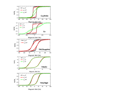
In order to study the magnetic anisotropy, the hysteresis loops were measured for all the studied samples with an in-plane magnetic field applied along various orientations (where is the in-plane angle between the magnetic applied field and one substrate edge), as shown on figure 2. The variations of the reduced remanent magnetization () were then investigated as function of . The magnetization loops show that single layers and TMJ on sapphire present clearly in-plane magnetic anisotropy and provide coercive fields () along the easy axis of 23 Oe, 48 Oe and 23 Oe in Co2MnGe, Co and TMJ, respectively. The hysteresis loops of TMJs on Si and MgO provide coercive fields of 33 Oe and 19 Oe, respectively, but do not depend on varies, suggesting the absence of anisotropy. The Co layer presents a high uniaxial anisotropy of about 300 Oe, as deduced from the hard axis magnetization loop (), most probably induced by the interface with the sapphire substrate [11]. The Co2MnGe single layer presents a complex anisotropy which cannot be simply described using a uniaxial anisotropy and complementary experiments should be done to clarify it. The hysteresis loop of TMJ grown on sapphire presents a narrow plateau for small applied fields suggesting an antiparallel alignment of the Co and Co2MnGe magnetizations and, consequently, only a very weak coupling of the two layers. Indeed, for a high applied magnetic field, the two magnetizations are parallel and aligned with it. When the sign of the applied field changes, due to the slight difference between the coercive fields of Co and of Co2MnGe, the magnetizations of the two layers do not simultaneously switch, thus leading to small plateau in the hysteresis loop. The observed differences between the TMJs and single layers reinforce the suggestion of an interfacial origin of the anisotropy.
III.2 Dynamic measurements
For each single layer, we assume a magnetic energy density which,
in addition to Zeeman, demagnetizing and exchange terms, is characterized
by the following anisotropy contribution:
(1)
For an in-plane applied magnetic field , the studied model provides
the following expression for the frequencies of the experimentally
observable magnetic modes:
(2)
In the above expression s-1.Oe-1 is the gyromagnetic factor and represents the in-plane (referring to one substrate edge) angle defining the direction of the magnetization ; and stand for the angles of an easy uniaxial planar axis and of an easy planar fourfold axis, respectively, with this substrate edge. , and are the in-plane uniaxial, the fourfold and the out-of-plane uniaxial anisotropy constant, respectively. In addition we state that and are positive. It is often convenient to introduce the effective magnetization , the uniaxial in-plane anisotropy field and the fourfold in-plane anisotropy field . In the case of an out-of-plane perpendicular applied magnetic field, the resonance frequency is given by:
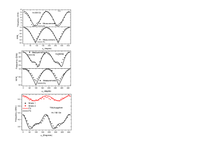
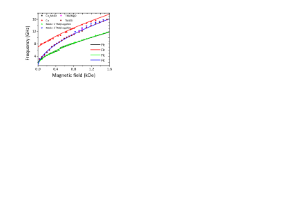
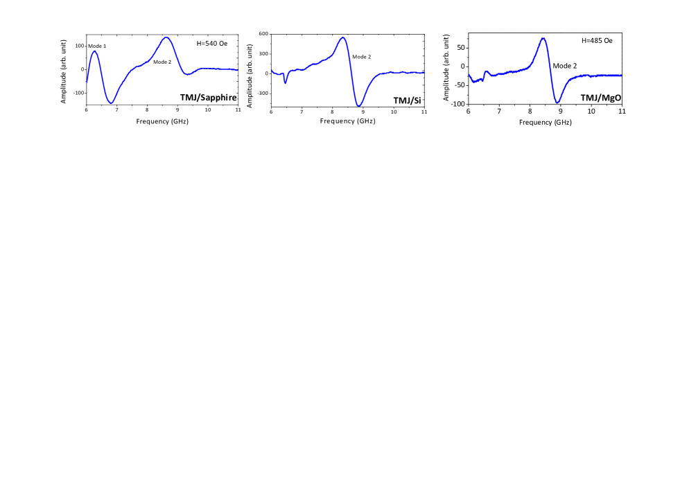
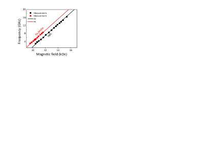
MS-FMR spectra have been recorded for in-plane and perpendicular applied fields, of variable amplitudes, for each sample. In the single films one resonance mode is observed, as expected: it is well described by the above model (figures 5 and 6 for Co, figures 4, 5 and 6 for Co2MnGe). The related fitted magnetic parameters are given in Table I for Co and for Co2MnGe. Notice that a uniaxial term well describes the in-plane anisotropy in the Co sample while both uniaxial and fourfold in-plane anisotropy are requested to give account for the data concerning Co2MnGe. In addition, the derived in-plane anisotropy characteristics are consistent with the above mentioned angular variation of the reduced remanent magnetization (). In the TMJs two resonance modes should be present: neglecting the interlayers coupling the first one (mode 1) is described by magnetic parameters near of the derived ones for the Co2MnGe single film and the second one (mode 2) is described by magnetic parameters near of the derived ones for the Co single film. This expected behavior is only observed in the TMJ grown on the sapphire substrate (figure 3). In the other TMJs the resonance study detects only a unique mode corresponding to mode 2. The absence of mode 1 reflects their less quality compared to TMJ on sapphire, which, due to its weak intensity, prevents its detection. In fact, the growth conditions Co2MnGe layer are surely optimal for TMJ on sapphire but most probably not for the other TMJs. In the three studied TMJs the fitted effective g factor and the effective demagnetizing field derived from the field dependence of the frequency of mode 2 are nearly identical to the obtained ones in the Co single film: 2.17 and 16 kOe, to compare to 2.17 and 15.2 kOe, respectively. Concerning mode1, observed in TMJ on sapphire, the fitted effective g factor and the effective demagnetizing field are again nearly identical to the obtained ones in the Co2MnGe single film: 2.02 and 9.2 kOe, to compare to 2.02 and 8.9 kOe, respectively. Finally, the in-plane anisotropy of mode is found to be uniaxial for mode 2, while in mode 1 uniaxial and fourfold terms provide comparable contributions.
IV Conclusion
Co2MnGe (13 nm) / Al2O3 (3nm) / Co (13 nm) TMJ deposited on a-plane sapphire, MgO and Si substrates have been prepared. For comparison, single films of Co2MnGe and Co of the same 13 nm thickness been also deposited on sapphire. Their structural, static and dynamic magnetic properties have been studied. Our X-rays diffraction measurements show that the Co2MnGe film is (110) oriented. The good quality of the TMJ on sapphire has been checked via high resolution transmission electron microscopy. The VSM measurements showed composited anisotropy in the case of TMJ on sapphire. However, no anisotropy has been revealed by the VSM hysteresis loops in the case of the other TMJs. A high uniaxial anisotropyis observed in the Co film, most probably induced the interface with sapphire substrate. MS-FMR measurements revealed two modes for TMJ on sapphire, attributed to the Co2MnGe and to the Co layer and one mode for the other TMJs, attributed and Co layer. The magnetic properties are strongly dependent on the interfaces quality and growth condition and can be used to check the TMJ quality. A good fit of all the experimental data, using appropriate values of the magnetic coefficients describing the free energy, is obtained.
References
- (1) R. W. Dave, G. Steiner, J. M. Slaughter, J. J. Sun, B. Craigo, S. Pietambaram, K. Smith, G. Grynkewich, M. DeHerrera, J. Åkerman, and S. Tehrani, IEEE Trans. Magn. 42, 1935 (2006).
- (2) P. P. Freitas, R. Ferreira, S. Cardoso and F. Cardoso, J. Phys.: Condens. Matt. 19, 165221 (2007).
- (3) A. A. Tulapurkar, Y. Suzuki, A. Fukushima, H. Kubota1, H. Maehara, K. Tsunekawa, D. D. Djayaprawira, N. Watanabe and S. Yuasa, Nature 438, 339 (2005) .
- (4) M Yamamoto, T Marukame, T Ishikawa, K Matsuda, T Uemura and M Arita, J. Phys. D: Appl. Phys. 39, 824 (2006).
- (5) K. Inomata, N. Ikeda, N. Tezuka, R. Goto, S. Sugimoto, M. Wojcik and E. Jedryka, Sci. Technol. Adv. Mater. 9, 014101 (2008).
- (6) E. A. Verduijn and K. Westerholt, J. Appl. Phys. 99, 084502 (2006).
- (7) F. Y. Yang, C. H. Shang, C. L. Chien, T. Ambrose, J. J. Krebs, G. A. Prinz, V. I. Nikitenko, V. S. Gornakov, A. J. Shapiro, and R. D. Shull, Phys. Rev. B 65, 174410 (2002).
- (8) P. G. Webster J. Phys.Chem. solids 32, 1221 (1971).
- (9) M. Belmeguenai, F. Zighem, T. Chauveau, D. Faurie, Y. Roussigné, S. M. Chérif, P. Moch, K. Westerholt, and P. Monod, J. Appl. Phys. 108, 063926 (2010).
- (10) M. Belmeguenai, F. Zighem, Y. Roussigné, S-M. Chérif, P. Moch, K. Westerholt, G. Woltersdorf, and G. Bayreuther Phys. Rev. B 79, 024419 (2009).
- (11) N. Metoki, Th. Zeidler, A. Stierle, K. Br/Shl and H. Zabel, J. Mag. Mag. Mat. 118, 57 (1992).
- (12) S. M. Rezende, C. Chesman, M. A. Lucena, A. Azevedo, F. M. de Aguiar, and S. S. P. Parkin, J. Appl. Phys. 84, 958 (1998).
- (13) A. Layadi, Phys. Rev. B 72, 024444 (2005).