Strongly aligned and oriented molecular samples at a kHz repetition rate
Abstract
Dedicated to Bretislav Friedrich on the occasion of his 60 birthday
We demonstrate strong adiabatic laser alignment and mixed-field orientation at kHz repetition rates. We observe degrees of alignment as large as at 1 kHz operation for iodobenzene. The experimental setup consist of a kHz laser system simultaneously producing pulses of 30 fs (1.3 mJ) and 450 ps (9 mJ). A cold 1 K state-selected molecular beam is produced at the same rate by appropriate operation of an Even-Lavie valve. Quantum state selection has been obtained using an electrostatic deflector. A camera and data acquisition system records and analyzes the images on a single-shot basis. The system is capable of producing, controlling (translation and rotation) and analyzing cold molecular beams at kHz repetition rates and is, therefore, ideally suited for the recording of ultrafast dynamics in so-called “molecular movies”.
I Introduction
Aligned and oriented molecules serve as ideal samples to study steric effects in chemical reactions Brooks (1976); Stapelfeldt and Seideman (2003) and to image the structure and dynamics of complex molecules directly in the molecular frame, if that is strongly confined, i. e., linked to the laboratory frame of the measurement. This would yield so-called “molecular movies” of the ongoing dynamics, conceivably without prior knowledge on the investigated system.
Bretislav Friedrich has been at the forefront of the development of methods to control complex molecules, including brute force orientation Friedrich and Herschbach (1991); Loesch and Remscheid (1990), laser alignment Friedrich and Herschbach (1995) and mixed-field orientation Friedrich and Herschbach (1999a, b). At that time, the degree of alignment and orientation was too weak to image molecular dynamics directly in the molecular frame. However, over the last two decades, the available degree of control has been constantly increased. The combination with rotational-state selection Holmegaard et al. (2009); Putzke et al. (2011) has improved the achievable control dramatically, with the strongest demonstrated degree of alignment so far of Holmegaard et al. (2009). In addition, recent results on the orientation of molecules in mixed fields show that the adiabaticity and the resulting degree of orientation strongly depend on the applied electric fields, i. e., the laser-pulse duration Nielsen et al. (2012).
Strong laser alignment and mixed-field orientation has been exploited in the recording of molecular frame photoelectron angular distributions of complex molecules Holmegaard et al. (2010). Controlled samples increase the contrast in all direct imaging experiments. They allow the simple averaging of many individual experiments, they simplify the data analysis, and no orientation relationship between patterns from randomly oriented molecules need to be derived numerically Spence and Doak (2004); Filsinger et al. (2011). Moreover, they are crucial to various advanced “photography” experiments: Tomographic reconstruction approaches for X-ray Pabst et al. (2010); Filsinger et al. (2011) or electron diffraction Reckenthaeler et al. (2009); Hensley et al. (2012) and photoelectron holography experiments of aligned molecules require typically Filsinger et al. (2011); Krasniqi et al. (2010).
Such a strong degree of alignment has, so far, only been achieved in adiabatic alignment experiments making use of very cold molecular beams and nanosecond laser pulses at a repetition rate of a few 10 Hz Kumarappan et al. (2006); Holmegaard et al. (2009). However, the low repetition rates renders time resolved studies of molecular dynamics, with their generally low count rates, tedious, at least, or even infeasible. Therefore, experimental setups which provide strong alignment at high repetition rates are highly desirable. This requires the production of cold molecular beams of complex molecules and strong laser fields with pulse durations that are comparable or longer than the rotational period of the molecules. The lack of nanosecond lasers with sufficient pulse energies at kHz repetition rates suggests the use of laser pulses generated by an amplified Ti:Sa laser system. However, the generation of such laser pulses with pulse durations on the order of 1 ns and the required peak intensities of W/cm3 is challenging. Moreover, a priori it has been unclear whether “heavy” molecules with a rotation time in the order of a few hundred picoseconds (like iodobenzene) can be strongly aligned by a sub-nanosecond, strongly linearly chirped broadband 800 nm laser pulse.
Recently, some relevant molecular beam setups with high repetition rates have been developed and some individual ingredients of the necessary control and detection details have been demonstrated Horio and Suzuki (2009); Ren et al. (2012); Irimia et al. (2009). A benchmark experiment demonstrating long-pulse alignment of molecules in a low-pressure continuous beam at 1 kHz repetition rate, probed with short ps x-ray pulses from a synchrotron source, has demonstrated weak alignment of Peterson et al. (2008). Impulsive alignment experiments have been performed, again exploiting continuous molecular beams, with lasers operating at kHz repetition rates Peronne et al. (2003); Rouzee et al. (2012). The achieved degree of alignment however is typically also only moderately strong (). This makes these approaches not very well suited for molecular-frame imaging studies of complex molecules. Moreover, in these experiments the alignment typically only persists for short periods of time ( ps), which severely limits the time-window for time-resolved experiments, esp. for large amplitude dynamics, such as conformer interconversion or folding motions.
Here, we present a new experimental setup that provides strongly aligned and oriented samples of state-selected molecules at a repetition rate of 1 kHz. This rate is a good compromise between current table-top laser systems, pulsed molecular beam sources, and high speed camera systems. In addition, it demonstrates a clear pathway for the sample preparation at upcoming light sources with high-repetition rates, such as x-ray free-electron lasers (XFELs), synchrotrons, and laser based high-harmonic generation (HHG) sources. In order to efficiently use these light sources, the capability of high repetition rate adiabatic alignment and orientation is highly desirable. Whereas the availability of synchronized pulses from high-power table-top laser systems is practically an intrinsic feature, XFEL facilities, such as the European XFEL in Hamburg, are actively pursuing the setup of high-repetition rate lasers that meet the requirements set by the current work.
II Experimental setup
The schematic of the experimental setup is shown in Figure 1.
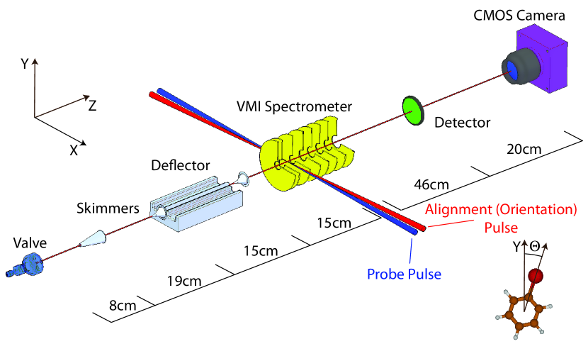
Details will be published in a longer account and only a brief description will be presented here. A pulsed molecular beam is provided by expanding 10 mbar of iodobenzene seeded in 120 bar of helium through an Even-Lavie valve Even et al. (2000) cooled to -20 ∘C. After passing two skimmers the molecular beam enters an electric deflector, where the molecules are dispersed according to their quantum state Filsinger et al. (2009a). The state selected molecular ensembles are aligned or oriented by laser or mixed dc-electric and laser fields Friedrich and Herschbach (1999a, b); Holmegaard et al. (2009); Ghafur et al. (2009), respectively, inside a velocity map imaging spectrometer (VMI) Eppink and Parker (1997). The angular confinement is probed through strong-field multiple ionization by a short laser pulse followed by Coulomb explosion of the molecule. The resulting I+ ions are velocity mapped onto a 40 mm diameter position sensitive detector (Photonis) consisting of a multi-channel-plate (MCP), a fast phosphor screen (P-46), and a high frame-rate camera. High speed oil-free pumping (4000 l/s for the source and 2000 l/s for deflection and detection chambers, respectively) and optimized operation conditions of the Even-Lavie pulsed valve allow for the generation of dense ( molecules/cm3 in the interaction volume) and cold (1 K) molecular beams, whose population distribution is further reduced to some ten rotational states by state-selection Filsinger et al. (2009a).
Alignment and ionization laser pulses are provided by an amplified femtosecond laser system (Coherent Legend Elite Duo HE USX NSI) at a repetition rate of 1 kHz. The total output power of the system is larger than 10 W with a bandwidth of nm centered at 800 nm. Directly behind the amplification stages the laser beam is split into two parts, an alignment (orientation) beam ( mJ/pulse) and a probe beam ( mJ/pulse). The duration of the alignment pulse can be compressed or stretched (negatively chirped) with an external compressor continuously from 40 fs up to 520 ps. The probe beam is compressed to 30 fs using the standard grating based compression setup. Since both beams are produced by the same amplifier system they are inherently synchronized. The two beams are incident on a 60 cm focal length lens parallel to each other with a transverse distance of 10 mm, resulting in field strength of up to W/cm2 and W/cm2 for alignment and probe pulse, respectively. The foci are overlapped in space and time in the molecular beam and in the center of the velocity map imaging spectrometer. Vertically scanning the lens allows probing different parts of the, typically, quantum state dispersed, molecular beam, i. e., to probe ensembles with varying rotational excitation and correspondingly varying effective dipole moments and effective polarizabilities. This motion is automatized and thus one can completely automatically measure the ion-distribution in the VMI as a function of vertical beam position. From this data, one can determine the molecular beam density, the degree of alignment, and the orientation all at once. A typical scan over the molecular beam at 1 kHz repetition rate takes about 1000 s (vide infra).
The imaging system CMOS camera (Optronis CL600x2) is operated at a camera-link-readout-limited resolution of pixel at sustained 1 kHz repetition rate. This corresponds to a spatial resolution of 80 µm on the phosphor screen. The typical spatial illumination on the camera corresponding to one ion is four pixels. The background corrected camera images are analyzed for every single shot with a centroiding algorithm on a standard PC computer, making use of eight available cores by sequentially distributing the images onto different cores. The coordinates of the ion hits are passed to the main data acquisition system. The single-shot analysis allows high signal rates exploiting the high saturation limit of the detection system.
III Results
III.1 1D Alignment
Figure 2 a) shows the degree of alignment 111The degree of alignment is defined as with being the two dimensional ion distribution on the detector. The angle is defined as the angle between the polarization of the alignment laser and the projection of the three dimensional ion velocity vector onto the two dimensional detector plane. The velocity is given by . as a function of the peak intensity of the alignment pulse; see the inset of Figure 1 for a definition of . The results are shown for a repetition rate of 1 kHz in solid black (deflector off) and dashed black (deflected beam) as well as for a repetition rate of 100 Hz in solid blue/grey (deflector off) and dashed blue/grey (deflected).
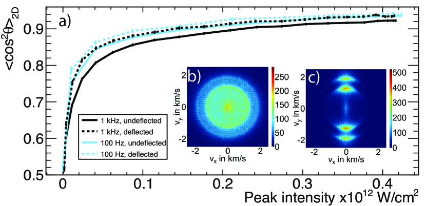
The observed power dependence of the degree of alignment for a cold beam is as expected Kumarappan et al. (2006). For randomly aligned molecules a degree of alignment is expected. The degree of alignment increases with increasing laser intensity, but is limited by . The 2D momentum image for I+ ions for the alignment-field-free case at 1 kHz repetition rate is shown in Figure 2 b). The distribution is circularly symmetric as expected for the case of an isotropic sample and the polarization of the probe laser pulse linear and perpendicular to the detector plane. The degree of alignment is given by . Figure 2 c) shows the corresponding ion distribution when the molecules are aligned at 1 kHz repetition rate along the alignment pulse polarization axis, i. e., linear, vertical and parallel to the detector plane. The number of ions is about three ions/pulse and the image has been recorded in less than 10 minutes. The peak laser intensity is W/cm2. The degree of alignment determined from the outer structure (between =1.7 km/s and =2.2 km/s) of the two dimensional ion distribution is . The radial structures in the ion images indicate that there are two fragmentation channels present in the Coulomb explosion of iodobenzene: the inner ring corresponds to recoiling from a singly charged phenyl, whereas the outer ring corresponds to recoiling from doubly charged phenyl Larsen et al. (1999). Using the outer ring for the determination of is favorable as it corresponds to the most sudden fragmentation channel and, therefore, to the best axial recoil conditions. The derived value underestimates the degree of alignment since the probe and alignment pulse have perpendicular polarization and, therefore, the least-aligned molecules are ionized with the highest efficiency Kumarappan et al. (2006).
A slightly higher degree of alignment is obtained when the valve is operated at 100 Hz repetition rate. The degree of alignment with the deflector off at 100 Hz repetition rate is comparable to the one obtained at 1 kHz repetition rate in the deflected beam. A slight increase of the degree of alignment to is observed in the deflected part of the beam at 100 Hz repetition rate. In order to investigate the reason for this behavior we have operated the valve at 100 Hz at a higher temperature and leaked helium gas into the chamber. Both, temperature and source chamber pressure, have been adjusted to match the conditions found at 1 kHz repetition rate. Under these conditions we observed a degree of alignment that matches the 1 kHz results. Therefore, the slightly smaller degree of alignment is attributed to a higher valve temperature and a higher background pressure in the source chamber when the valve is operated at 1 kHz. The lower peak intensity of the employed alignment pulse is the reasons for the smaller value of compared to previous reported best value obtained using a 20 Hz 10 ns injection seeded Nd:YAG laser Holmegaard et al. (2009). Obviously, these experimental limits could be solved by exploiting higher-power lasers and considerably larger vacuum pumps, which have not been available for this study.
The pulse length of the alignment pulse is 450 ps. The rotational period of iodobenzene (J-type revival) is 707.7 ps Poulsen et al. (2004); Dorosh et al. (2007). Thus, the laser pulse length is shorter than the rotational period of iodobenzene, placing this study in the intermediate regime between adiabatic and impulsive alignment – closer to the adiabatic case. The observed degree of alignment clearly indicates comparable control as in previously reported adiabatic alignment experiments Larsen et al. (1999); Holmegaard et al. (2009). The detailed influence of non-adiabatic effects for the studied system is not clear and a more detailed investigation of the alignment dynamics as a function of the laser pulse duration is in preparation.
III.2 1D Orientation
Figure 3 shows the ratio of ions in the upper half of the detector images divided by the total number of ions as a function of the angle .
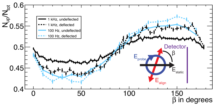
The color scheme is as in Figure 2a). The angle is defined as the angle between the polarization of the alignment laser and the static electric field of the VMI spectrometer, V/cm, as shown in the inset of Figure 3. The probe beam is circularly polarized. The observed dependence of the orientation as a function of the angle beta is as expected from previous low-repetition rate experiments Holmegaard et al. (2009); Filsinger et al. (2009a). The molecules are better oriented in the deflected part of the beam, where the population is confined to the energetically lowest, i. e., the most polar, rotational states. In addition we observe better orientation at 100 Hz than at 1 kHz repetition rates. The reason for this is the slightly increased rotational temperature of the 1 kHz molecular beam, as discussed above. In comparison with the orientation for the same molecule obtained using 10 ns alignment-laser pulses Holmegaard et al. (2009) we obtain a considerably smaller degree of orientation in the current experiment. This can be attributed to the nonadiabatic mixing of levels in the near-degenerate doubles created by the strong laser field, which has been shown to be more prominent for shorter laser pulses Nielsen et al. (2012). This is also in agreement with earlier theoretical studies that have shown that the degree of impulsive orientation, using short laser pulses, is limited by the magnitude of the applied DC electric field Rouzee et al. (2009).
III.3 Molecular-beam deflection dependence
In Figure 4 the vertical molecular beam profiles (Figure 4 c) and the dependence of the degrees of alignment (Figure 4 a) and orientation (Figure 4 b) on the position in the molecular beam, measured in a single lens scan as described above, are shown.
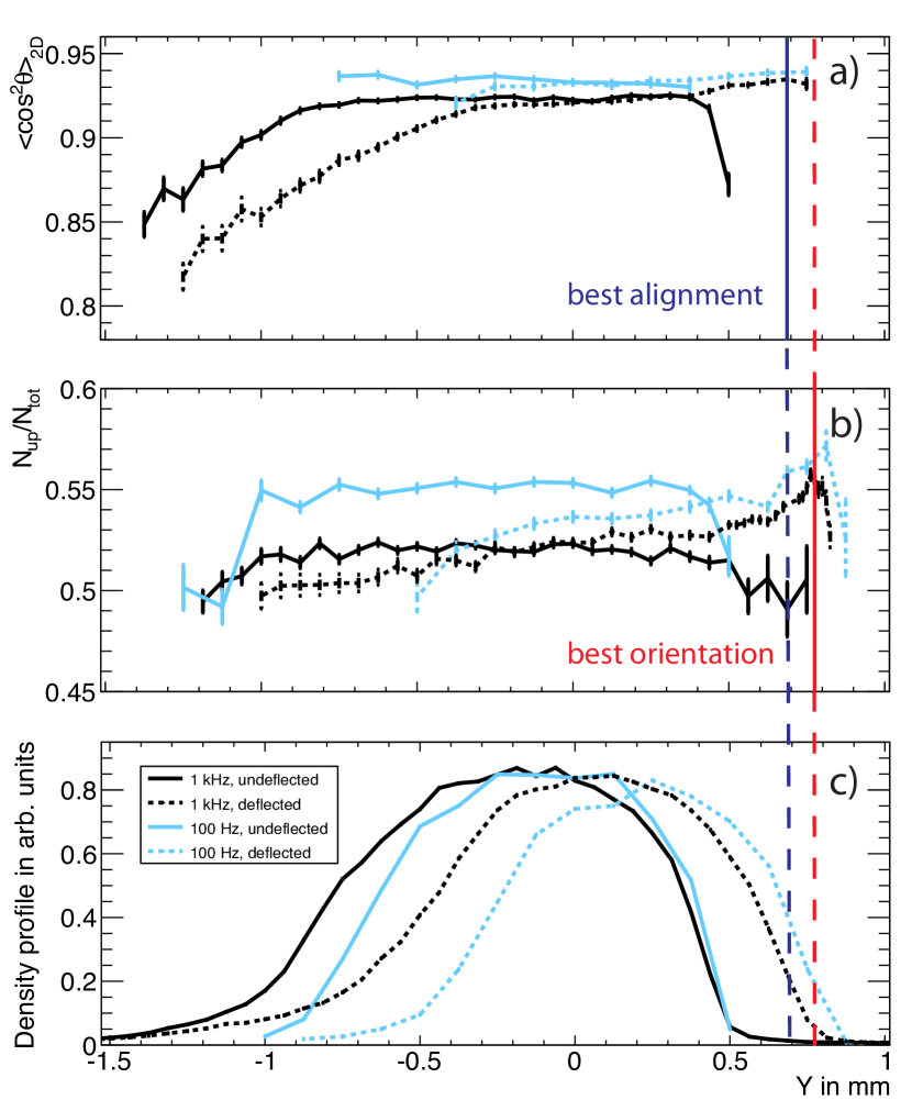
The color scheme of the plots is the same as in Figure 2a). The molecular beam profiles and the observed deflection, for an applied deflector voltage of 12 kV, are in good agreement with previous measurements Filsinger et al. (2009a). For the beam with the deflector off, the observed degrees of alignment and orientation are practically constant over the main part of molecular beam profile. Towards the sides, however, the achievable control decreases, which is especially pronounced for the alignment measurement. This demonstrates that the molecular beam is considerably warmer at the sides than in the center. This is attributed to collisions with the rest gas and to interference with mechanical apertures, i. e., skimmers. When applying an inhomogeneous electric field, the molecules are deflected upwards. Moreover, the molecular beam is dispersed according to the molecules’ effective dipole moments, or, correspondingly, according to their rotational states. The most polar, lowest-energy rotational states are deflected the most, and this is reflected in the increased degrees of alignment and orientation in the deflected part of the molecular beam. This accounts for the larger contributions of lower quantum states which show a large deflection. In addition, a decrease of the degree of alignment and orientation in regions where the high rotational states remain (right part of the molecular beam profile) is observed. Helium is not present anymore in the deflected part of the molecular beam since its trajectory is not influenced by the electric deflector. As the degree of alignment and orientation is dependent on the position in the dispersed molecular beam, the properties of the beam change as a function of the vertical laser probe position. This opens up the possibility for advanced multidimensional investigations, i. e., the observation of state-selective dynamics, in the future. It can also be used to increase the understanding of the deflection process of complex molecules, including the investigation of nonadiabatic couplings of rotational states by the “slowly” changing electric fields. Moreover, it enables the study of the nature of ensembles of molecules in a single molecular quantum states in mixed fields, as in a previous study on impulsive alignment and mixed-field orientation of a nearly pure ground state ensemble of OCS Nielsen et al. (2011, 2012).
IV Conclusions and Outlook
In conclusion, a high-repetition-rate experimental molecular physics setup has been developed. It allows the preparation of very strongly aligned and oriented samples of quantum-state-selected cold molecules at a 1 kHz repetition rate. The dependence of the degree of alignment and orientation on the position in the molecular beam has been analyzed. Both parameters are enhanced when probing the state-selected molecules in the deflected part of the beam. A maximum degree of alignment at 1 kHz of has been obtained for a 450 ps long pulse with a peak intensity of W/cm2. The obtained degree of orientation is . This value is lower than what was demonstrated in previous studies Holmegaard et al. (2009), and it is limited by the combination of the applied DC electric field in the VMI spectrometer and the pulse duration of the alignment pulse, in accordance with previous analyses Nielsen et al. (2012); Rouzee et al. (2009).
The pulse duration of our alignment pulse is continuously tunable over a wide range from fs to ps; this will allow the investigation of the influence of this duration on the (non)adiabaticity on the alignment and orientation Nielsen et al. (2012). Preliminary measurements show that the degree of alignment is increasing when the pulse duration is shortened, due to the stronger peak intensity available in our setup. At the same time, revivals structures start to appear, indicating clear nonadiabatic effects in the alignment dynamics. It is likely, that for each molecular sample a trade-off between adiabatic and non-adiabatic driving of the alignment can be found to ensure an optimal degree of alignment and orientation.
The demonstrated strong control over molecules at high repetition rates promises the feasibility of novel investigations of “weak” processes, such as chemical dynamics, using molecular-frame photoelectron angular distributions, photoelectron holography, or X-ray or electron diffraction imaging. For the applied, relatively short, alignment laser pulses, only moderate pulse energies, on the order of 10 mJ are necessary. It is envisioned, that such pulses will be available at hundreds of kHz or even MHz repetition rates in the near future. For instance, similar setups are envisioned for the European XFEL, where burst mode lasers with similar pulse energies are under consideration and electric state selectors can be implemented for arbitrary repetition rate molecular beams. This opens up the possibility of performing time resolved dynamics studies using molecular frame photoelectron angular distributions Hansen et al. (2011) or photoelectron holography Landers et al. (2001); Krasniqi et al. (2010). Moreover, the controlled samples serve as ideal targets in x-ray or electron diffraction experiments Filsinger et al. (2011); Reckenthaeler et al. (2009); Hensley et al. (2012), and they hold great promise toward attosecond and high-harmonic-generation experiments of complex molecules, where the molecular alignment and orientation can be exploited to modulate and enhance the output Velotta et al. (2001). Moreover, the state-selection process inherently separates structural isomers Filsinger et al. (2008, 2009b), which is a necessary ingredient to investigate ultrafast dynamics of structural isomers, such as charge migration in various conformers of glycine Kuleff and Cederbaum (2007).
Acknowledgements.
We thank the DESY-FS infrastructure groups for support, HASYLAB/Petra III for hosting our laboratory, the CFEL staff for administrative and technical support and Vinod Kumarappan for the camera software. This work has been supported by the excellence cluster “The Hamburg Centre for Ultrafast Imaging - Structure, Dynamics and Control of Matter at the Atomic Scale” of the Deutsche Forschungsgemeinschaft. N. L. M. M. acknowledges financial support by the Joachim Herz Stiftung.References
- Brooks (1976) P. Brooks, Science 193, 11 (1976).
- Stapelfeldt and Seideman (2003) H. Stapelfeldt and T. Seideman, Rev. Mod. Phys. 75, 543 (2003).
- Friedrich and Herschbach (1991) B. Friedrich and D. R. Herschbach, Nature 353, 412 (1991).
- Loesch and Remscheid (1990) H. J. Loesch and A. Remscheid, J. Chem. Phys. 93, 4779 (1990).
- Friedrich and Herschbach (1995) B. Friedrich and D. Herschbach, Phys. Rev. Lett. 74, 4623 (1995).
- Friedrich and Herschbach (1999a) B. Friedrich and D. Herschbach, J. Chem. Phys. 111, 6157 (1999a).
- Friedrich and Herschbach (1999b) B. Friedrich and D. Herschbach, J. Phys. Chem. A 103, 10280 (1999b).
- Holmegaard et al. (2009) L. Holmegaard, J. H. Nielsen, I. Nevo, H. Stapelfeldt, F. Filsinger, J. Küpper, and G. Meijer, Phys. Rev. Lett. 102, 023001 (2009).
- Putzke et al. (2011) S. Putzke, F. Filsinger, H. Haak, J. Küpper, and G. Meijer, Phys. Chem. Chem. Phys. 13, 18962 (2011).
- Nielsen et al. (2012) J. H. Nielsen, H. Stapelfeldt, J. Küpper, B. Friedrich, J. J. Omiste, and R. González-Férez, Phys. Rev. Lett. 108, 193001 (2012).
- Holmegaard et al. (2010) L. Holmegaard, J. L. Hansen, L. Kalhøj, S. L. Kragh, H. Stapelfeldt, F. Filsinger, J. Küpper, G. Meijer, D. Dimitrovski, M. Abu-samha, C. P. J. Martiny, and L. B. Madsen, Nat. Phys. 6, 428 (2010).
- Spence and Doak (2004) J. C. H. Spence and R. B. Doak, Phys. Rev. Lett. 92, 198102 (2004).
- Filsinger et al. (2011) F. Filsinger, G. Meijer, H. Stapelfeldt, H. Chapman, and J. Küpper, Phys. Chem. Chem. Phys. 13, 2076 (2011).
- Pabst et al. (2010) S. Pabst, P. J. Ho, and R. Santra, Phys. Rev. A 81, 043425 (2010).
- Reckenthaeler et al. (2009) P. Reckenthaeler, M. Centurion, W. Fuss, S. A. Trushin, F. Krausz, and E. E. Fill, Phys. Rev. Lett. 102, 213001 (2009).
- Hensley et al. (2012) C. J. Hensley, J. Yang, and M. Centurion, Phys. Rev. Lett. 109, 133202 (2012).
- Krasniqi et al. (2010) F. Krasniqi, B. Najjari, L. Strüder, D. Rolles, A. Voitkiv, and J. Ullrich, Phys. Rev. A 81, 033411 (2010).
- Kumarappan et al. (2006) V. Kumarappan, C. Z. Bisgaard, S. S. Viftrup, L. Holmegaard, and H. Stapelfeldt, J. Chem. Phys. 125, 194309 (2006).
- Horio and Suzuki (2009) T. Horio and T. Suzuki, Rev. Sci. Instrum. 80 (2009).
- Ren et al. (2012) X. Ren, V. Makhija, and V. Kumarappan, Phys. Rev. A 85 (2012), 10.1103/PhysRevA.85.033405.
- Irimia et al. (2009) D. Irimia, D. Dobrikov, R. Kortekaas, H. Voet, D. A. van den Ende, W. A. Groen, and M. H. M. Janssen, Rev. Sci. Instrum. 80 (2009).
- Peterson et al. (2008) E. R. Peterson, C. Buth, D. A. Arms, R. W. Dunford, E. P. Kanter, B. Krassig, E. C. Landahl, S. T. Pratt, R. Santra, S. H. Southworth, and L. Young, Astrophys. Lett. & Comm. 92, 094106 (2008).
- Peronne et al. (2003) E. Peronne, M. Poulsen, C. Bisgaard, H. Stapelfeldt, and T. Seideman, Phys. Rev. Lett. 91 (2003), 10.1103/PhysRevLett.91.043003.
- Rouzee et al. (2012) A. Rouzee, F. Kelkensberg, W. K. Siu, G. Gademann, R. R. Lucchese, and M. J. J. Vrakking, J. Phys. B 45 (2012).
- Even et al. (2000) U. Even, J. Jortner, D. Noy, N. Lavie, and N. Cossart-Magos, J. Chem. Phys. 112, 8068 (2000).
- Filsinger et al. (2009a) F. Filsinger, J. Küpper, G. Meijer, L. Holmegaard, J. H. Nielsen, I. Nevo, J. L. Hansen, and H. Stapelfeldt, J. Chem. Phys. 131, 064309 (2009a), arXiv:0903.5413 [physics] .
- Ghafur et al. (2009) O. Ghafur, A. Rouzee, A. Gijsbertsen, W. K. Siu, S. Stolte, and M. J. J. Vrakking, Nat. Phys. 5, 289 (2009).
- Eppink and Parker (1997) A. T. J. B. Eppink and D. H. Parker, Rev. Sci. Instrum. 68, 3477 (1997).
- Note (1) The degree of alignment is defined as with being the two dimensional ion distribution on the detector. The angle is defined as the angle between the polarization of the alignment laser and the projection of the three dimensional ion velocity vector onto the two dimensional detector plane. The velocity is given by .
- Larsen et al. (1999) J. J. Larsen, H. Sakai, C. P. Safvan, I. Wendt-Larsen, and H. Stapelfeldt, J. Chem. Phys. 111, 7774 (1999).
- Poulsen et al. (2004) M. D. Poulsen, E. Peronne, H. Stapelfeldt, C. Z. Bisgaard, S. Viftrup, E. Hamilton, and T. Seideman, J. Chem. Phys. 121, 783 (2004).
- Dorosh et al. (2007) O. Dorosh, E. Białkowska-Jaworska, Z. Kisiel, and L. Pszczółkowski, J. Mol. Spec. 246, 228 (2007).
- Rouzee et al. (2009) A. Rouzee, A. Gijsbertsen, O. Ghafur, O. M. Shir, T. Baeck, S. Stolte, and M. J. J. Vrakking, New J. Phys. 11 (2009).
- Nielsen et al. (2011) J. H. Nielsen, P. Simesen, C. Z. Bisgaard, H. Stapelfeldt, F. Filsinger, B. Friedrich, G. Meijer, and J. Küpper, Phys. Chem. Chem. Phys. 13, 18971 (2011).
- Hansen et al. (2011) J. Hansen, H. Stapelfeldt, D. Dimitrovski, M. Abu-Samha, C. Martiny, and L. Madsen, Phys. Rev. Lett. 106, 073001 (2011).
- Landers et al. (2001) A. Landers, T. Weber, I. Ali, A. Cassimi, M. Hattass, O. Jagutzki, A. Nauert, T. Osipov, A. Staudte, M. H. Prior, H. Schmidt-Böcking, C. L. Cocke, and R. Dörner, Phys. Rev. Lett. 87, 013002 (2001).
- Velotta et al. (2001) R. Velotta, N. Hay, M. Mason, M. Castillejo, and J. Marangos, Phys. Rev. Lett. 87, 183901 (2001).
- Filsinger et al. (2008) F. Filsinger, U. Erlekam, G. von Helden, J. Küpper, and G. Meijer, Phys. Rev. Lett. 100, 133003 (2008), arXiv:0802.2795 [physics] .
- Filsinger et al. (2009b) F. Filsinger, J. Küpper, G. Meijer, J. L. Hansen, J. Maurer, J. H. Nielsen, L. Holmegaard, and H. Stapelfeldt, Angew. Chem. Int. Ed. 48, 6900 (2009b).
- Kuleff and Cederbaum (2007) A. I. Kuleff and L. S. Cederbaum, Chem. Phys. 338, 320 (2007).