Nanogroove array on thin metallic film as planar lens with tunable focusing
Abstract
Numerical results for the distributions of light transmitted through metallic planar lenses composed of symmetric nanogroove arrays on the surfaces of a gold film are presented and explained. Both the near- and far-field distributions of the intensity of light transmitted are calculated by using a Green’s function formalism. Results for an optimal transverse focus based on a quadratic variation of groove width are obtained. Meanwhile, a significant dependence of the focal length on the wavelength of light incident from the air side through the gold film into a dielectric substrate is found for this detector configuration.
I Introduction
There is considerable interest at the present time in shaping the spatial dependence of the intensity of light transmitted through a metal film pierced by a one-dimensional array of slits with subwavelength widths, as an alternative to refractive lensing. Sun and Kim sun have studied numerically the transmission of light through a finite periodic array of subwavelength slits piercing a free-standing metal film with a convex dependence of its thickness. The incident beam is focused by this metallic lens. Shi et al. shi studied numerically the focusing of light transmitted through a metallic film of constant thickness pierced by an array of equally spaced nanoslits of varying widths. It was argued that the focusing action is based on propagation across the opaque metal film of surface plasmon polaritons supported by the slits (metal-dielectric-metal structures) of varying widths, thus ensuring an enhanced transmission and a phase change along the film surface that lead to the constructive interference. The focusing of light by such a structure deposited on a dielectric substrate was demonstrated experimentally by Verslegers et al. fan . The experimental results were in an excellent agreement with FDTD simulations fan . However, the focus distance was much shorter than predicted by the model proposed previously.
In this paper we demonstrate the focusing effect by calculating numerically the spatial distribution of the intensity of light transmitted through a metal film sandwiched between a cladding and a dielectric substrate whose surfaces are modeled by two finite aligned and reversed arrays of nanogrooves of finite depth. We have chosen to define transmissivity as the squared modulus of the ratio of the transmitted to the incident H-field amplitude for polarization. In this case there are no surface polaritons propagating through the film as there are no slits that completely pierce the metallic film. In the case of the extraordinary transmission of light through a metal film with a periodic nanoslit array, the surface polaritons supported by the slits play a minor role in the phenomenon, and what is more it is not necessary to have slits that completely pierce the metallic film to achieve the enhanced transmission maradudin1 . When a periodic nanogroove array is illuminated by polarized light, whose magnetic vector is parallel to the generators of the array, surface plasmon polaritons (SPPs) associated with the film-cladding and the film-substrate interfaces are excited maradudin1 ; wellems , and are diffracted by the structure into transmitted volume waves in the substrate. The periodicity of the array enhances the excitation of surface plasmon polaritons associated with the cladding-film interface and the conversion of surface plasmon polaritons associated with the substrate-film interface into volume waves in a range of SPP frequencies whose wavenumbers are in the vicinity of the boundary of the second Brillouin zone, i.e. when , where is the period of the array and is the surface plasmon polariton wavelength. As a result the transmission through gold and silver films as a function of wavelength maradudin1 shows sharp peaks and dips in a range of SPP frequencies whose wavenumbers are near the boundary of the second Brillouin zone at both interfaces of the film.
It is also not necessary to have slits that completely pierce the metallic film to achieve the focusing of light transmitted through it when the array is finite. The conversion of either surface polaritons supported by the slits or surface polaritons supported by the film itself into the volume wave in the substrate is a diffraction process, and since the system is two-dimensional it produces volume cylindrical waves propagating away from the surface into the substrate. A finite number of secondary sources of cylindrical waves separated by subwavelength distances can produce the field focusing effect. The additional phases of each of the secondary sources changes the focal depth and width, but affect only slightly the focus distance. The effect can be modeled as follows. The periodic array of slits or nanogrooves ensures the transmission through the otherwise nontransparent film, while the now transparent aperture produces the focusing, in exactly the same manner as a refractive nanolens in a diffractive regime. The focus distance is then determined primarily by the aperture size, i.e. by the size of the array, and the wavelength of light in the substrate. The intensity distribution in the far field is then determined by the Fresnel diffraction by the aperture.
In this paper we discuss focused patterns of nanogroove arrays and do not elaborate on differences between nanoslit and nanogroove arrays, since they are physically equivalent in producing the focusing effect except for some quantitative difference in the intensity of the transmitted field. A simulation study was undertaken to search for the best way to improve the quality of focus by changing the groove profile and groove width variation. Planar nanolenses will have numerous applications in polarimetric imaging devices, solar cells, light emitting diodes, and nanophotonics systems. Some preliminary results of this work was reported earlier. huang2
This paper is organized as follows. In Section II, we employ a previously developed model and formalism, maradudin1 ; wellems modified to include an arbitrary sequence of groove width variation. Based on this formalism, numerical results are presented for the comparison of the focused patterns of field intensity produced by different sequences of groove width variation and different groove shapes. The conclusions drawn from these results are briefly summarized in Section III.
II Model and Numerical Results
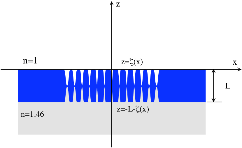
In this paper, we consider the model shown in Fig. 1 for a nanogroove array, in which the top [ at ] and bottom [ at ] surface profile functions maradudin1 employed for modeling a nanogroove array patterned in a thin gold film are chosen to be
| (1) |
where is the thickness of the unpatterned gold film, is the index for labeling grooves, is the total number of grooves in the array, is the groove depth, is the period of the groove array, and is an arithmetic sequence representing a specific pattern of groove-width variation. The surface profile functions in Eq. (1) are symmetric with respect to the middle groove centered at , and (or ) corresponds to a Gaussian (or a quartic) functional form for a groove, respectively. The arithmetic sequence in Eq. (1) is assumed to be
| (2) |
where represents the width of the central groove, and (or ) corresponds to a quadratic (or a linear) groove-width variation, separately. The spatial distributions of the electromagnetic fields on the air side (), inside the patterned gold film (), and on the side of the dielectric substrate () can be calculated by using a Green’s function formalism. maradudin1 ; wellems
In our numerical calculations, whose results are presented below, we assume that the metal film is illuminated by a normally incident polarized plane wave, whose magnetic-field component has a unit amplitude, or by a normally incident polarized plane wave, whose electric-field component has a unit amplitude. The parameters defining the film have the values m, m, m, , and nm for the width of the central groove. The frequency-dependent complex refractive index for the gold film is obtained by interpolation from the data in the paper by Johnson and Christy christy . The values of the other parameters, such as , , , , and the incident light wavelength , used in our numerical calculations will be given in the figure captions.
II.1 Focusing by a finite aperture
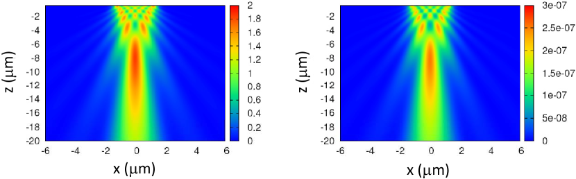
In Fig. 2 we present color level plots of the intensity of the field of light (left) of and (right) of polarization transmitted through the gold film from the air cladding into the dielectric substrate. The surface profile functions are arrays of periodic grooves of the same half widths ().
As can be seen from plot presented in Fig. 2 the interference pattern of the transmitted light of both polarizations exhibits a focal spot with the same focal distance but the intensity of the polarized field is seven orders of magnitude weaker. The additional interference maxima are of the same strength as the primary focal spot. Thus, in spite of the fact that the groove arrays considered in our calculations are finite (the aperture size is m), and the period is significantly smaller then the wavelength of light in air and in the substrate, the enhanced transmission in polarization is obvious. The intensity distribution of the primary focal spot is described by
| (3) |
where and are the Fresnel integrals, and is the array length. The focal length (the position of the maximum of the intensity) is , and is inversely proportional to the wavelength of light in the substrate . From the calculated (-polarization) and (-polarization) with groove width variation (not shown here), we find that while the constructive interference is completely destroyed by introducing the quadratic groove width variation in the case of polarized light, the quality of the primary focal spot is considerably improved and the subsidiary maxima of the interference pattern are suppressed in the case of polarized light. Note that the focal length decreases. From the calculated total (integrated over the transmission angles from to ) transmission coefficient as a function of the wavelength of the polarized incident light for different combinations of the cladding and substrate materials (not shown here), we clearly see the enhanced transmission in comparison with , although the array is limited to a few wavelengths. In addition, the introduction of a weak quartic change in the width of the grooves leads to a slight shift in the position and the broadening of the enhanced transmission peak, but does not destroy it.
II.2 Wavelength effect on the focal length
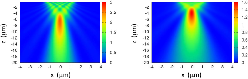
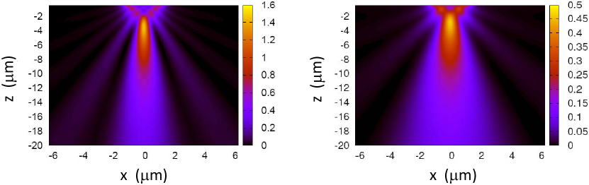
Figure 3 presents a comparison of the spatial distributions of when polarized light is incident normally from the upper air side (corresponding to a detector configuration) at m (left panel) and m (right panel). Here, a quartic functional form () is assumed for the symmetric nanogroove array on a gold film, which has a quadratic groove-width variation (). It is clear from Fig. 3 that the focal spot shifts upward from m to m when is increased from m to m. The positions of the maxima of the intensity are in agreement with the inverse dependence of the focal length on the wavelength. Meanwhile, the longitudinal ( direction) size of the focal spot shrinks, although its transverse ( direction) size remains constant. This provides a possibility for multi-color detection if several active detection layers with specific absorption wavelengths are embedded at different depths underneath the nanogroove array on top of a quantum-well photodetector. huang1 The magnification also decreases, which is obviously related to the fact that the overall transmission decreases as the wavelength increases.
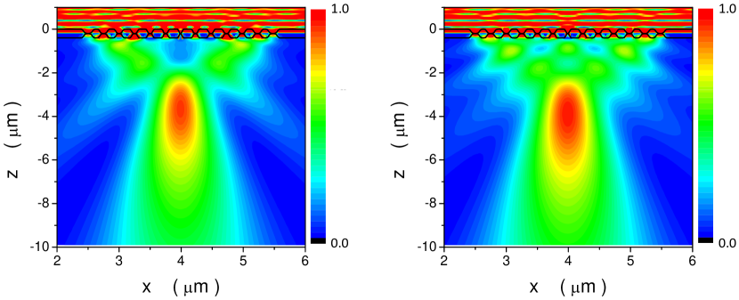
In Fig. 4 we present the color level plot of the spatial distribution of the field intensity in the case when the dielectric substrate is adjusted to produce the strongest transmission at the given wavelength. In this case, the wavenumbers of SPP polaritons associated with the film-substrate interface are the same, so that at both wavelengths the effective aperture for SPP is the same. This is the reason for the same focal distance. It is clearly seen that the magnification is greatly increased for both chosen wavelengths.
II.3 Difference in detector and emitter configurations
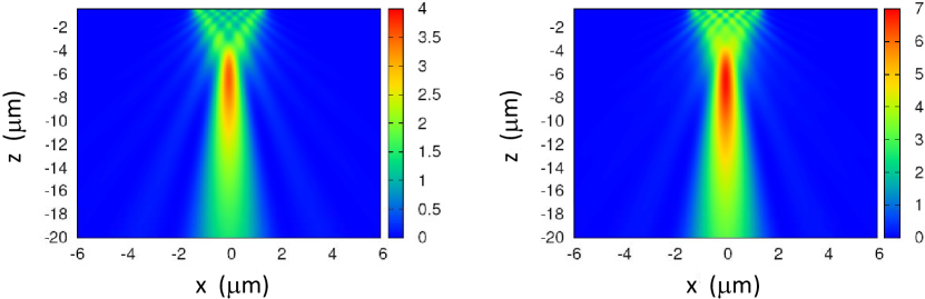
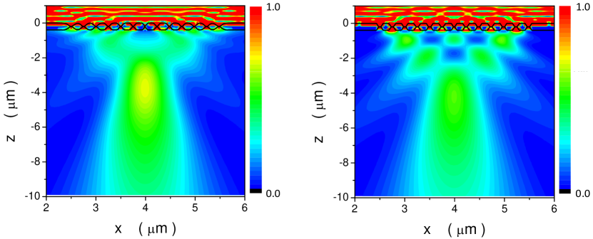
For device-configuration comparison, we show in Fig. 5 the results for when the roles of air and dielectric substrate are interchanged, so that polarized light is incident normally from the upper cladding side with and is transmitted into the air (corresponding to an emitter configuration) at m (left panel) and m (right panel), respectively. Here, a quartic functional form for a groove, as well as a quadratic groove-width variation, are also assumed for modeling the nanopatterned symmetric groove array. In this case, however, we find no shift of the focal spot in the direction with a change of . In this configuration the wavelength in the substrate (air) is considerably larger than in the case described in the preceding section. This leads to shorter focal length ( times). Since the decay length of the groove near field in the dielectric substrate side scales like , raether the inverse dependence of the focal length on the wavelength will be completely masked by the increase of with . At the same time, the transmitted field is reduced, as is seen by comparing Fig. 5 with Fig. 3. In addition, the transverse size of the focal spot is enlarged on the air side as is increased from m to m. From the results shown in Fig. 5, we expect that this emitter configuration can be employed for constructing a wavelength-insensitive planar lens with a very thin dielectric substrate that is transparent to light of wavelength m.
We also study the effect of a dielectric substrate on focusing action from the calculated for polarized light incident normally from the upper air side at m (not shown here), from which we find that the focusing power almost disappears when the dielectric substrate is replaced by air. Meanwhile, the non-focused bright spot is seen to move upward as is reduced from to . On the other hand, the focal spot shifts downward as is increased from to , in agreement with the diffractive regime of the lens, which is accompanied by an expansion of the longitudinal size of the focus spot.
II.4 Effects of groove shape and groove-width variation
To study the effect of groove shape, as well as the effect of groove-width variation, we com- bine four calculated spatial distributions for in Fig. 6 obtained with polarized light of wavelength m incident normally in an emitter configuration. A quartic functional form is assumed for the groove array (two upper panels) with a quadratic (left) and a linear (right) groove-width variation, to investigate the effect of groove-width variation. We also show the result for (lower-right panel) with a constant groove width. In addition, the calculated (lower-left panel) for the case with a Gaussian functional form () is included in Fig. 6 to demonstrate the groove-shape effect. By comparing the two upper panels of Fig. 6, we find that the quadratic variation of groove width leads to an enhanced focusing power with a smaller spot size in both directions. For a constant groove width, the focusing action is completely lost. As the corners of a groove are rounded by a Gaussian functional form, in comparison with a quartic one, the focusing power is partially suppressed, but the focal spot does not move at all.
III Conclusions and Remarks
In conclusion, when light is incident from the upper air side, we have demonstrated that the focal length of a planar metallic lens based on a variable nanogroove array deposited on a dielectric substrate can be controlled by varying the wavelength of the incident light. How- ever, this wavelength-tunability of the focal length for a metallic planar lens is completely absent when the light is incident from the substrate side. These numerical results can be applied to the design of a multi-color photodetector in which a number of active detection layers with specific absorption wavelengths are embedded at different depths underneath the top groove array. Moreover, the enhanced focusing power of a metallic planar lens with a quadratic groove-width variation is observed in comparison with that of a linear one. A range for the refractive index of a dielectric substrate is found as an imposed restriction for the tunable focal length of a metallic planar lens. The sharpness of a groove corner is shown to play an important role in the focusing power of a metallic planar lens through the comparison of a groove in a quartic functional form with that in a Gaussian one.
When a -polarized incident light illuminates a periodic nanogroove array, SPPs, which are associated with the film-cladding and film-substrate interfaces, can be excited. These excited SPP waves will be diffracted by the array into volume cylindrical waves after their transmission as long as the SPP wavenumbers fall into the vicinity of the boundary of the second Brillouin zone. Diffraction induces a coupling between SPP modes with different reciprocal lattice vectors and produces a gap at either the center or the boundary of the first Brillouin zone. These generated cylindrical waves, which are separated by subwavelength distances, lead to the field focusing effect. We note that the periodic array of nanogrooves is only responsible for the transmission through the otherwise nontransparent film. It is the transparent aperture that produces the focusing. As a result, the focus distance is decided by both the size of the array and the wavelength of light in the substrate, which allows for a tunable focusing.
When the total number, 2M + 1, of grooves in a metallic planar lens is increased, we expect to see a significant reduction in the transverse size of a focus spot, which facilitates an even smaller pixel size for a photodetector focal-plane-array to improve its detectivity, as well as a suppression of cross-talk between different pixels. levine
Acknowledgements.
We would like to thank the Air Force Office of Scientific Research (AFOSR) for its support.References
- (1) Z. Sun and H. K. Kim, Appl. Phys. Lett. 85, 642 (2004).
- (2) H. Shi, C. Wang, C. Du, X. Luo, X. Dong, and H. Gao, Opt. Exp. 13, 6815 (2005).
- (3) L. Verslegers, P. B. Catrysse, Z. Yu, J. S. White, E. S. Barnard, M. L. Brongersma, and S. Fan, Nano Lett. 9, 235 (2009).
- (4) B. Baumeier, T. A. Leskova and A. A. Maradudin, J. Opt. A: Pure Appl. Opt. 8, S191 (2006).
- (5) L. D. Wellems, D. H. Huang, T. A. Leskova, and A. A. Maradudin, J. Appl. Phys. 106, 053705 (2009).
- (6) L. D. Wellems, D. H. Huang, T. A. Leskova, and A. A. Maradudin, Proc. SPIE 7792, 77920S (2010).
- (7) P. B. Johnson and R. W. Christy, Phys. Rev. B6, 4370 (1972).
- (8) D. H. Huang and M. O. Manasreh, Phys. Rev. B54, 5620 (1996).
- (9) H. Raether, Surface Plasmons on Smooth and Rough Surfaces and on Gratings, (Springer-Verlag, Berlin, 1988).
- (10) B. F. Levine, J. Appl. Phys. 74, R1 (1993).