FLUXCAP: A flux-coupled ac/dc magnetizing device
Abstract
We report on an instrument for applying ac and dc magnetic fields by capturing the flux from a rotating permanent magnet and projecting it between two adjustable pole pieces. This can be an alternative to standard electromagnets for experiments with small samples or in probe stations in which an applied magnetic field is needed locally, with advantages that include a compact form-factor, very low power requirements and dissipation as well as fast field sweep rates. This flux capture instrument (FLUXCAP) can produce fields from to mT, with field resolution less than mT. It generates static magnetic fields as well as ramped fields, with ramping rates as high as T/s. We demonstrate the use of this apparatus for studying the magnetotransport properties of spin-valve nanopillars, a nanoscale device that exhibits giant magnetoresistance.
pacs:
07.55.-w,75.60.-d,75.47.DeThe effective synthesis and control of magnetic fields is of longstanding fundamental interest for probing magnetic-field dependent phenomena. The ability to effectively magnetize materials is also of tremendous technological importance for testing magnetic devices, such as sensors, magnetic memories and other small magnetic elements, as well as for characterizing a new generation of hybrid devices with semiconducting and magnetic properties Hueso and Dediu (2009); Yi et al. (2010); Wang et al. (2012). This demand for magnetizing devices has motivated the recent emergence of many different methods for generating and directing magnetic fields Chang et al. (2010); Arena et al. (2009); Gilbert et al. (2012); Heigl et al. (2002); Li et al. (2012); Nolle et al. (2012). From static systems involving permanent magnets to electromagnetic systems built upon current carrying coils and superconducting magnets, there are many options when designing a source of magnetic fields. Most designs consider: the maximum desired field, the field homogeneity in the sample area, the size and access to the field region for probes (e.g. optical or electrical), the field sweep-rate and the magnet’s linearity. In practice, the design factors are highly dependent on the researcher’s aim.
Standard electromagnets have several disadvantages. The current-carrying electromagnets are typically large, heavy units that can limit the optical access to a device between the poles, consume high power in order to drive sufficient current through the coils and require water cooling in order to mitigate the Ohmic heating.
In this paper, we introduce an ac/dc magnetizing device based on the coupling of magnetic flux into two parallel steel bars from a diametrically magnetized permanent magnet that is mounted to a rotating stage. We denote this instrument FLUXCAP for its flux capture characteristics. The FLUXCAP is an alternative to standard magnetizing devices for generating the fields between two soft pole pieces. It has been designed for testing small magnetic devices, whose lateral size is much smaller than the diameter of the pole pieces. This apparatus has several advantages over standard magnets: it is portable and can run entirely on battery power; the only Ohmic losses are in the motor, for which overheating can easily be prevented by heat-sinking; and the high speed by which the magnet can be rotated permits higher field ramping rates than many electromagnets which typically have a large inductance. Furthermore, the FLUXCAP permits optical access and is high vacuum compatible, permitting a wide range of test applications.
I Physical Description and Principles of Operation
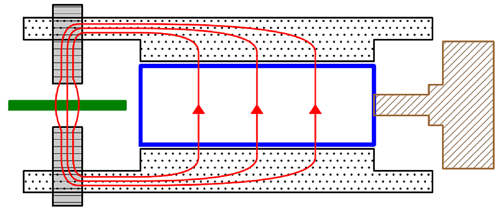
Figure 1 illustrates our implementation of a FLUXCAP magnet. The yoke of the FLUXCAP is a Neodymium Iron Boron (NIB) magnetic rod (diameter 0.5 inches, length 2 inches) NIB as indicated by the blue rectangle in the figure. It is magnetized uniformly along the rod diameter. The NIB magnet is attached to a motor (brown hashed) which permits continuous rotation of the rod about its long axis, and consequently, continuous rotation of the magnetization in the plane perpendicular to the rotation axis. The magnet yoke is flanked on both sides by soft pole pieces – two low-carbon steel bars as indicated by the black dotted regions (0.25 square cross-section, length 6 inches). Two threaded holes near the termination of the bars accommodate one-quarter inch threaded steel rods, completing the pole pieces. The pole gap is adjusted by threading the removable pole pieces (grey with black stripes) into and out of the threaded holes in the steel bars. Test devices, as indicated by the green solid rectangle, are inserted in the gap between the pole pieces and a commercial Gaussmeter is placed at the sample location to monitor the field produced between the poles. This entire apparatus is lightweight, weighing less than 10 kg.
The soft pole pieces capture the flux incident from the yoke and focus the field lines across the relatively short air gap between the pole pieces. As the NIB rod is rotated on its axis, the net flux captured into the pole pieces from the yoke varies periodically. This rotation translates into a nearly sinusoidally varying magnetic field between the two poles.
The operation of the FLUXCAP magnet depends upon the capture of magnetic flux from a permanent magnet into two parallel steel bars placed on each side of the magnet. Maximal flux transfer occurs when the magnetization of the diametrically magnetized permanent magnet is directed toward the faces of the steel bars and minimal flux is transferred when the magnetization is oriented perpendicular to the faces of the bars. Thus, the permanent magnet is rotated by a motor in order to vary the flux captured by the steel bars by varying the angle between the magnetization direction and the steel bar faces.
We present a model for understanding the basic dependence of the flux in the steel rods as a function of the magnetization direction of the permanent magnet. Equation (1) presents the field from an infinite uniformly magnetized rod with diametric magnetization in cylindrical coordinates:
| (1) |
Here , where is the saturation magnetization of the permanent magnet. and are the radial and angular cylindrical coordinates. is the radius of the permanent magnet rod. The geometry of this arrangement is further depicted in Fig. 2(a). While the real magnet is finite in extent, we believe that this approximately captures the relevant behavior of this system because the length of the magnetic rod is much larger than the distance between the rod and the steel bars (approximately one-eighth of an inch). We are ultimately interested in the field lines extending radially outward and into the steel piece, which is set by , the maximum magnetic field at the surface of the magnet. This value can be directly measured with a magnetic field sensor placed on the surface of the magnet, which we have measured as 0.993 T. Having established an expression for the field, we proceed to a description of the flux in the steel bars.
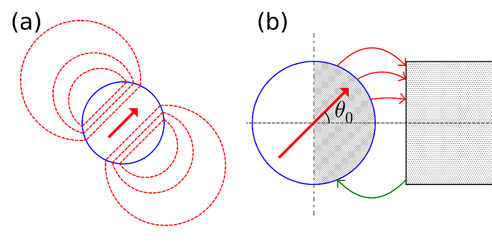
The proximity of the two parallel steel bars have a non-negligible effect on the fields from the permanent magnet. We assume the magnetic field on the surface of the permanent magnet is left unchanged, but that the magnetic field lines are distorted in such a way that field lines on the right semicircular face of the magnet terminate on the right steel bar and lines on the left semicircular face terminate on the left steel bar, as depicted graphically in Fig. 2(b). Therefore, we can estimate the total magnetic flux into the right steel bar as the net magnetic flux exiting the right semicircular face of the magnet. Equation (2) gives the total flux as a function of , the angle between the magnetization and the steel surface normal:
| (2) |
where is the length of the magnet.
Finally, the magnetic flux is directed toward two pole pieces extending into the gap between the parallel steel bars. For sufficient distances between the permanent magnet and the pole pieces, all of the field between the pole pieces is indirectly coupled through the flux in the steel bars. The magnitude of this field is inversely proportional to the surface area of the pole tips. It is also sensitive to the pole gap and distance of the pole pieces from the magnet, both of which can contribute to flux losses through leakage along the gap between the parallel bars and fringing at the poles. We present an implementation of this method of flux capture and direction that exploits a pole displacement and tip surface area that gives a fraction of a Tesla magnetic field in a cm3 volume. We also adjust the pole gap in order to control the peak field applied between the poles, as discussed below.
II FLUXCAP Operation
II.1 Variable Amplitude and Precision Control
The gap between two steel pole pieces can be adjusted to change the maximum applied field. This varies the peak field amplitude of the alternating magnetic field when the magnet is rotated continuously. Reducing the peak field amplitude may be useful in studying devices that have multiple magnetic layers, some of which are not intended to be remagnetized.
Reducing the peak field amplitude may also be useful in applications where field precision is of most importance. For example, the FLUXCAP can be used to generate dc magnetic fields with the magnet positioned using a stepper motor. The field precision is related to the minimum rotation that the motor can produce and the maximum field amplitude. Each finite step from a stepper motor (typically 0.9 degrees) corresponds to a change in field of just over one percent of the peak amplitude. Therefore, larger pole separations may be desirable to obtain finer control over magnetic fields.
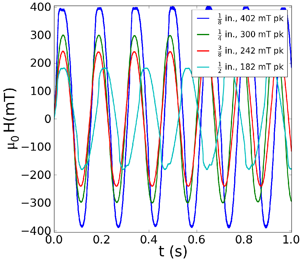
Figure 3 demonstrates the ability to adjust the maximum field between the poles. We adjusted the 0.25 inch diameter threaded rods to create pole gaps in 0.125 inch increments between 0.125 and 0.5 inches and operated the FLUXCAP using a 12 V battery-powered dc motor. As the permanent magnet was rotated continuously at a rate of 400 revolutions per minute, field measurements were made using a commercial Gaussmeter and then digitized at 48 kHz. We demonstrate control over the peak field amplitude from 400 mT down to 180 mT.
The peak amplitude at the pole gap of 0.125 inches allows us to estimate the efficiency by which we capture the flux from our NIB yoke into the two pole pieces. Assuming an effective fringing area about 50% larger than the pole face, we compute the efficiency, , to be approximately 15%. We estimate that 85% of the flux is being lost to leakage across the space between the steel bars. The FLUXCAP could be made more efficient by employing higher permeability materials and through optimizing the pole piece geometry.
II.2 Variable frequency and Field Ramping
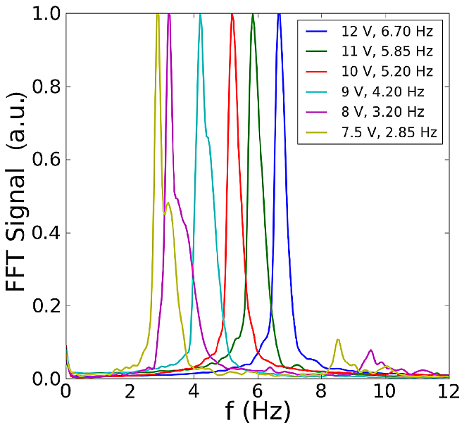
The FLUXCAP magnet can operate either as a stationary or an alternating field magnetizing device. In the alternating field operation mode, a dc motor generates continuous rotation of the NIB yoke which drives an alternating magnetic field between the poles. By changing the frequency of rotation, a variation of the field sweeping rate (frequency) can be achieved. Figure 4 shows the Fast Fourier Transform spectra of the alternating magnetic field between the poles of the FLUXCAP under different rotation speeds of the motor. Measurements were taken under a 0.25 inch pole gap using the same field acquisition methods described above. We demonstrate alternating magnetic fields with frequencies ranging between 3 Hz and 7 Hz for voltages ranging from 7 V to 12 V placed across the motor.
For the lower frequencies, the FFT spectra show wide sidebands due to a varying rotation rate of the permanent magnet. We used a 12 V/84 oz-in 37 mm dc motor Pololu.DCMotor , which uses 12 W of power (1 A or 20% of its stall current) at 12 V. At lower voltages, the maximal output torque of the motor decreases and rotating the magnet away from the steel bars requires larger torque. For inputs below 7 V, this motor stalls. We use a higher torque stepper motor when slower field ramp rates are needed Lin.Stepper .
The frequency of the alternating magnetic field corresponds to an effective linear ramping rate over 85 percent of the maximum amplitude field. For the frequencies given here and the 0.3 T peak amplitude for a 0.25 inch pole separation, the ramping rates vary from 10 T/s down to 4 T/s for the lowest rotation frequency. These high field ramping rates make the FLUXCAP an efficient rapid magnetizing device when used with a continuously rotating motor. Slower variation of the field has been achieved with the use of a high torque stepper motor, permitting field ramping rates to decreasing by several orders of magnitude. This could be relevant to studies of thermally-activated magnetization reversal in which a magnet’s coercivity is (typically logarithmically) sensitive to the sweeping rate Wernsdorfer et al. (1997); Gopman et al. (2012); Jiang et al. (2003); Sun et al. (2002a, 2001, b).
III Application: Fast magnetizing of spin-valve nanopillars
The FLUXCAP magnet can facilitate fast characterization of many magnetic devices such as spin-valve nanopillars – a two terminal magnetic device composed of two ferromagnetic layers separated by a thin non-magnetic layer Mangin et al. (2006); Gopman et al. (2012). Typically a spin-valve device exhibits two stable resistance states depending on the relative magnetization orientation of the two magnetic layers from the Giant Magnetoresistance (GMR) effect Baibich et al. (1988); Binasch et al. (1989); Valet and Fert (1993); Pratt et al. (1991). The spin-valve state can be toggled between high (antiparallel) and low (parallel) resistance by applied magnetic fields. Characteristic of spin-valve nanopillars is the use of ferromagnetic layers with different coercivities, such that one ferromagnet is typically fixed (a reference layer) while the other ferromagnet (the free layer) can be switched relative to the reference magnet. We can determine the relative orientation of the layers by measuring the device resistance as a function of the applied magnetic field. More critically, using the 7 Hz rotation rate of the FLUXCAP, we can rapidly conduct MR hysteresis loops to measure the coercivity of the free layer and the giant magnetoresistance of the spin-valve. The FLUXCAP also could be incorporated into a probe setup for characterizing the properties of spin-valve and magnetic tunnel juction (MTJ) devices.
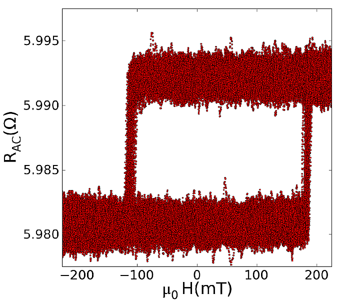
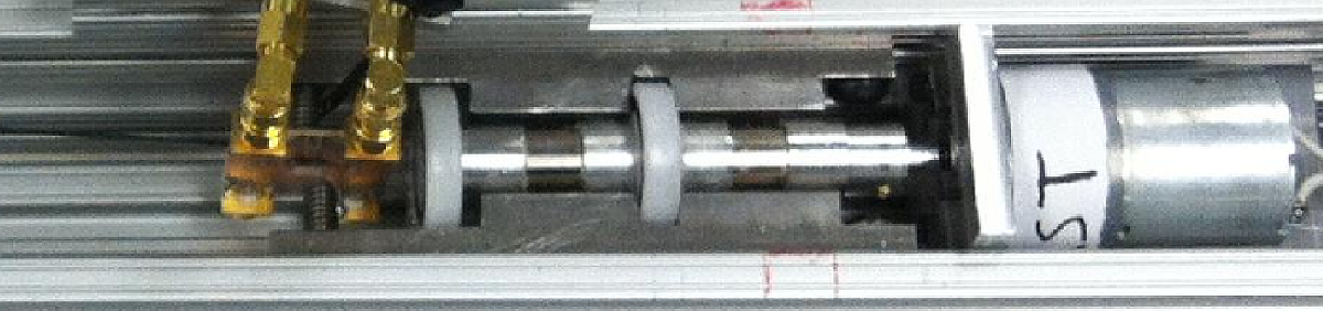
Figure 5 demonstrates a testing configuration for this apparatus. A spin-valve nanopillar device is wire bonded to a coplanar waveguide board, which is in turn has been soldered to end-launch coaxial jacks. The waveguide is mounted rigidly to the outer Aluminum rail of the apparatus such that the device is centered between the two pole pieces. A commercial Gaussmeter probe is also mounted on the aluminum rail and is attached to one of the pole pieces. A small ac excitation current probes the differential resistance across the 300 50 spin-valve nanopillar, whose physical properties have been described in detail elsewhere Mangin et al. (2006). The FLUXCAP is configured with a one-quarter inch pole gap and 12 V power to run the motor at 7 Hz.
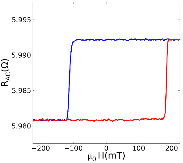
Figure 6 shows over 100 hysteresis loops recorded from 20 seconds of operating the FLUXCAP. Sharp changes in the differential resistance indicate toggling of the magnetization of the free layer from “up” (anti-parallel) to “down” (parallel) relative to the reference layer. As mentioned previously, the reference layer has a coercivity over 1 T, and is kept fixed during these measurements. Due to the thermally activated nature of magnetization reversal, a characteristic distribution of switching fields is apparent in this ensemble of hysteresis loops. It is therefore effective to consider an averaged hysteresis loop, such as the one depicted in Fig 7. From this figure, we estimate a coercivity of 150 mT and a GMR ratio () of 0.2%, which is consistent with similar devices Gopman et al. (2012); Bedau et al. (2010a, b).
IV Conclusions
We have demonstrated the operation of the FLUXCAP, a compact magnetizing device based upon the capture and focusing of flux from a rotating permanent magnet. This device can perform most of the same tasks as conventional electromagnet based magnetizing devices in that it can synthesize static and dynamic magnetic fields over a broad range of field values. Yet the FLUXCAP immediately presents itself as an elegant alternative: it operates as an ac magnetizing device requiring only a 12 V battery and a dc motor; its power consumption is marginal (12 W), and it does not require water cooling. The pole pieces are modular - it is straightforward to change the maximum field applied by varying the pole gap or even substituting a threaded rod with a different bevel or chamfer. This permits easy modifications to the magnitude and homogeneity of the applied field with minor changes in the FLUXCAP design. Furthermore, large field ramp rates are possible with FLUXCAP and have been demonstrated for studying spin-valve nanopillar devices. This enables statistical studies of thermally activated magnetization reversal, quick resetting of magnetic devices and testing the dynamic response of magnetic field sensors.
FLUXCAP magnets are versatile enough to function well in a variety of other applications. The setup could be made UHV compatible – in fact, the permanent magnet and motor could be placed outside of the UHV chamber and the flux coupled into the chamber with the soft steel core. FLUXCAP magnets can clearly be used for electronic transport measurements and could be integrated into probe stations. For example, it could be used to add magnetic capabilities to a semiconductor tester. By designing the shape of pole pieces and the position to place the sample, one can achieve different field directions using the FLUXCAP. Finally, it is easy to imagine combining two or three such magnets to generate a two-dimensional or even three-dimensional vector field for sophisticated measurements.
Acknowledgments
We appreciate Dr. Stéphane Mangin of Nancy Université and Dr. Eric E. Fullerton of the University of California, San Diego for providing the spin-valve samples used in the characterization of magnetic properties used in this study. We would also like to acknowledge Dr. James Rantschler of Xavier University of Louisiana for fruitful discussions leading to the design of FLUXCAP. This research was supported by NSF Grant No. DMR-1006575.
References
- Hueso and Dediu (2009) L. Hueso and V. A. Dediu, Nature Materials 8, 707 (2009).
- Yi et al. (2010) J. B. Yi, C. C. Lim, G. Z. Xing, H. M. Fan, L. H. Van, S. L. Huang, K. S. Yang, X. L. Huang, X. B. Qin, B. Y. Wang, et al., Physical Review Letters 104, 137201 (2010).
- Wang et al. (2012) F. Wang, F. Macia, M. Wohlgenannt, A. D. Kent, and M. E. Flatte, Physical Review X 2, 021013 (2012).
- Chang et al. (2010) W.-H. Chang, J.-H. Chen, and L.-P. Hwang, Magnetic Resonance Imaging 28 (2010).
- Arena et al. (2009) D. A. Arena, Y. Ding, E. Vescovo, S. Zohar, Y. Guan, and W. E. Bailey, Review of Scientific Instruments 80, 083903 (2009).
- Gilbert et al. (2012) M. Gilbert, H. C. Mertins, M. Tesch, O. Berges, H. Feilbach, and C. M. Schneider, Review of Scientific Instruments 83, 025109 (2012).
- Heigl et al. (2002) F. Heigl, O. Krupin, G. Kaindl, and K. Starke, Review of Scientific Instruments 73, 369 (2002).
- Li et al. (2012) J. Li, E. Jin, H. Son, A. Tan, W. N. Cao, C. Hwang, and Z. Q. Qiu, Review of Scientific Instruments 83, 033906 (2012).
- Nolle et al. (2012) D. Nolle, M. Weigand, P. Audehm, E. Goering, U. Wiesemann, C. Wolter, E. Nolle, and G. Schuetz, Review of Scientific Instruments 83, 046112 (2012).
- (10) This study used Neodymium Iron Boron (NIB) magnets purchased from K & J Magnetics, http://www.kjmagnetics.com.
- (11) This study used a 12 V 19:1 Metal DC Gearmotor (37mm Shaft) with 84 oz-in torque and 500 rpm. The motor is from Pololu Metal Gearmotors, http://www.pololu.com.
- (12) For slower field sweeping we use a High Torque (175 oz-in) Stepper Motor. It can be found under model number 5709M from Lin Engineering, http://www.linengineering.com.
- Wernsdorfer et al. (1997) W. Wernsdorfer, E. B. Orozco, K. Hasselbach, A. Benoit, B. Barbara, N. Demoncy, A. Loiseau, H. Pascard, and D. Mailly, Physical Review Letters 78 (1997).
- Gopman et al. (2012) D. B. Gopman, D. Bedau, S. Mangin, C. H. Lambert, E. E. Fullerton, J. A. Katine, and A. D. Kent, Applied Physics Letters 100, 062404 (2012).
- Jiang et al. (2003) Y. Jiang, S. Abe, T. Nozaki, N. Tezuka, and K. Inomata, Physical Review B 68, 224426 (2003).
- Sun et al. (2002a) J. Z. Sun, L. Chen, Y. Suzuki, S. S. P. Parkin, and R. H. Koch, Journal of Magnetism and Magnetic Materials 247, PII S0304 (2002a).
- Sun et al. (2001) J. Z. Sun, J. C. Slonczewski, P. L. Trouilloud, D. Abraham, I. Bacchus, S. S. P. Parkin, and R. H. Koch, Applied Physics Letters 78 (2001).
- Sun et al. (2002b) J. Sun, L. Chen, Y. Suzuki, S. Parkin, and R. Koch, Journal of Magnetism and Magnetic Materials 247, L237 (2002b).
- Mangin et al. (2006) S. Mangin, D. Ravelosona, J. A. Katine, M. J. Carey, B. D. Terris, and E. E. Fullerton, Nature Materials 5 (2006).
- Baibich et al. (1988) M. N. Baibich, J. M. Broto, A. Fert, F. N. Vandau, F. Petroff, P. Eitenne, G. Creuzet, A. Friederich, and J. Chazelas, Physical Review Letters 61 (1988).
- Binasch et al. (1989) G. Binasch, P. Grunberg, F. Saurenbach, and W. Zinn, Physical Review B 39, 4828 (1989).
- Valet and Fert (1993) T. Valet and A. Fert, Physical Review B 48 (1993).
- Pratt et al. (1991) W. P. Pratt, S. F. Lee, J. M. Slaughter, R. Loloee, P. A. Schroeder, and J. Bass, Physical Review Letters 66 (1991).
- Bedau et al. (2010a) D. Bedau, H. Liu, J. Z. Sun, J. A. Katine, E. E. Fullerton, S. Mangin, and A. D. Kent, Applied Physics Letters 97, 262502 (2010a).
- Bedau et al. (2010b) D. Bedau, H. Liu, J. J. Bouzaglou, A. D. Kent, J. Z. Sun, J. A. Katine, E. E. Fullerton, and S. Mangin, Applied Physics Letters 96, 022514 (2010b).