1.5 GHz Pulse Generation From a Monolithic Waveguide Laser With a Graphene-Film Saturable Output Coupler
Abstract
We fabricate a saturable absorber mirror by coating a graphene film on an output coupler mirror. This is then used to obtain Q-switched mode-locking from a diode pumped linear cavity waveguide laser inscribed in Ytterbium-doped Bismuthate Glass, with high slope and optical conversion efficiencies. The laser produces mode-locked pulses at1039nm, with 1.5GHz repetition rate at an average 202mW output power. This performance is due to the combination of the graphene saturable absorber with the high quality laser glass.
Carbon nanotubes (CNTs) and graphene have emerged as promising saturable absorbers (SA) for a variety of applicationsHasan_am_2009 ; Bonaccorso_np_2010 ; Sun_pe_2012 , opening a new phase in the development of passively Q-switchedPopa_apl_2011 and mode-locked lasersPopa_apl_2012 ; Sun_an_2010 ; Popa_apl_2010 ; Sun_nr_2010 ; Zhang_oe_2012 ; Ma_ol_2012 ; Zhao_ol_2010 ; Wang_nn_2008 ; Valle_apl_2006 ; Beecher_apl_2010 ; Lagatsky_2012 . While the predominantly used semiconductor saturable absorber mirrors (SESAMs) are limited by their narrow wavelength rangeOkhotnikov_njp_2004 , and complex fabricationKeller_po_2004 , CNTs and graphene have simple, cost-effective production and integrationHasan_am_2009 ; Bonaccorso_np_2010 ; Popa_apl_2010 ; Sun_pe_2012 ; Popa_apl_2011 ; Popa_apl_2012 ; Sun_an_2010 ; Sun_nr_2010 ; Zhang_oe_2012 ; Ma_ol_2012 ; Zhao_ol_2010 ; Wang_nn_2008 ; Valle_apl_2006 ; Beecher_apl_2010 ; Lagatsky_2012 ; bonamt . Broadband operation is achieved with CNTs by combining tubes of different diametersWang_nn_2008 . However, for a particular wavelength, only CNTs in resonance are used, the rest contributing insertion lossesSun_an_2010 . Graphene has an inherent ultra-wide spectral range due to the linear dispersion of the Dirac electronsHasan_am_2009 ; Bonaccorso_np_2010 ; Sun_pe_2012 ; Popa_apl_2011 ; Sun_an_2010 ; Sun_nr_2010 . This, along with the ultrafast recovery timeBrida_2012 and low saturation fluencePopa_apl_2010 ; Sun_an_2010 , makes it an excellent SAHasan_am_2009 ; Sun_an_2010 ; Sun_nr_2010 ; Zhang_oe_2012 ; Zhao_ol_2010 ; Popa_apl_2010 .
Saturable absorption can also lead to a regime of Q-switched mode-locking (QML)Honninger_josab_1999 , where the laser output consists of mode-locked pulses within a Q-switched envelopeHonninger_josab_1999 . This arises due to Q-switching instabilities in the cavityHonninger_josab_1999 , typically due to long (i.e.1s) upper state lifetimes of the gain media in solid state lasersHonninger_josab_1999 . These lasers are useful for applications where the pulse energy stored within the Q-switched envelopeHonninger_josab_1999 is valuable, such as nonlinear frequency conversionBoyd_no , medical applicationsChung_jb_2009 , and micromachiningNolte_josab_1997 . With the emerging trend in miniaturization of optical devices based on on-chip integration, the development of ultrafast lasers requires a complementary balance between device compactness and performanceValle_apl_2006 ; Beecher_apl_2010 . Ultra-compact high repetition rate (1GHz) lasers are very useful for applications such as nonlinear microscopyMertz_con_2004 , frequency combsDiddams_josab_2010 and spectroscopyMoreno_josab_2011 . The ease of SA integration into a compact cavity plays an important roleValle_apl_2006 ; Beecher_apl_2010 . Lasers employing a waveguide cavity allow device compactness, meanwhile emulating the advantages of fiber lasers, such as high beam qualityOkhotnikov_njp_2004 and efficient heat dissipationValle_apl_2006 ; Beecher_apl_2010 ; Okhotnikov_njp_2004 . Of the numerous methods for waveguide fabrication, a simple yet reliable technology is ultrafast laser inscription (ULI)Valle_joa_2009 , which utilizes100fs focused pulses to induce permanent modifications within a substrateValle_joa_2009 . Mode-locked ULI waveguide lasers have been demonstrated using CNT-SAsValle_apl_2006 ; Beecher_apl_2010 . However, the fiber ring cavityValle_apl_2006 ; Beecher_apl_2010 did not allow its miniaturization, thus high pulse rates.
Here we report pulse generation in a compact, ULI inscribed waveguide laser in Ytterbium-doped Bismuthate Glass (Yb:BG), by using a graphene film (GF) transferred to an output coupler (OC) mirror as a SA. We get mode-locked pulses with 1.5GHz repetition rate and 202mW average output power, with a 48% slope efficiency (i.e. rate of output to pump power in excess of the lasing thresholdGrivas_pqe_2011 ) and 38% optical-to-optical conversion efficiency (i.e. rate of output to pump powerGrivas_pqe_2011 ). The slope efficiency is high compared with that typical of monolithic pulsed waveguide lasers (e.g. 27%)Choudhary_ol_2012 .
A variety of approaches have been used to make graphene-based SAs. For example, graphene-polymer composites, fabricated from dispersions produced by liquid phase exfoliation (LPE) of graphitebonamt , have been used to mode-lock fiber lasers at 1.5Hasan_am_2009 ; Popa_apl_2010 ; Sun_nr_2010 and 2mZhang_oe_2012 . Films grown by chemical vapour deposition (CVD) with 1 layerLagatsky_2012 , 1-2 layersMa_ol_2012 , and non-uniform multi-layersZhao_ol_2010 , have been used to mode-lock solid-state lasers at 2mMa_ol_2012 ; Lagatsky_2012 and fiber lasers at 1mZhao_ol_2010 . Ref.Martinez_apl_2011, used flakes produced by micromechanical cleavage of graphite, with 4-40 layers, for mode-locking of fiber lasers at 1.5m. LPE graphene-polymer compositesPopa_apl_2011 , and flakes (10-40 layers) grown by carbon segregation on SiCYu_an_2010 , have been used for Q-switching of fiber lasers at 1.5m and solid-state lasers at 1m, respectively. Graphene oxide (GO) was also used as SA, either as a film in solid-state lasers at 2mLiu_lpl_2012 , or as composite in fiber lasers at 1.5mBonaccorso_np_2010 . However, GO is an insulating material with many defects and gap statesMattevi_afm_2009 , and may not offer the wideband tunability of graphene. Carbon segregation and CVD require high substrate temperaturesbonamt ; Ma_ol_2012 ; Lagatsky_2012 ; Liu_lpl_2012 , followed by transfer to the target substrateMa_ol_2012 ; Zhao_ol_2010 ; Lagatsky_2012 . Micromechanically cleaved graphene has high structural and electronic qualityBonaccorso_np_2010 , but is limited in terms of yield, thus impractical for large-scale applicationsbonamt . LPE has the advantage of scalability, room temperature processing and high yield, and does not require any growth substratebonamt . Dispersions produced by LPE can easily be embedded into polymers composites and integrated into various systemsBonaccorso_np_2010 ; bonamt .
Here we adopt a novel approach and use LPE graphene in a polymer-free film. This makes it suitable for high-power applications and device miniaturization. The GF-SA is prepared as follows. Graphite flakes (Sigma Aldrich) undergo LPEHernandez_nn_2008 and are dispersed in deionised water with sodium deoxycholate, as for Refs.Sun_an_2010, ; Zhang_oe_2012, . High Resolution Transmission Electron Microscopy (HRTEM), optical and Raman Spectroscopy are then used to characterize the dispersions. HRTEM shows that the sample consists of26% single-,22% bi- and18% tri-layersZhang_oe_2012 ; Hasan_pssb_2010 , with1m average size. The dispersion then undergoes vacuum filtration via 25nm pore-size filters. This blocks the flakes, while allowing water to pass through, resulting in a GF. This is then placed on an OC mirror, to be used in the laser, and on a quartz plate, for optical characterization, by applying pressure and heat (80∘C, to improve adhesion) for two hours, followed by dissolution of the filter in acetone. The film is45nm thick, as determined by profilometry. The GF density is0.72g/cm3, derived by measuring with a microbalance the filter weight before and after the GF deposition. This is3 times smaller than the density of bulk graphite.
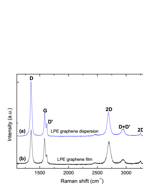
Raman spectra are acquired at 457, 514, 633nm using a Renishaw InVia micro-Raman spectrometer. Fig.1(a) plots a typical Raman spectrum of graphene flakes in the dispersion. Besides the G and 2D peaks, significant D and D’ bands are also presentFerrari_prl_2006 ; Ferrari_prb_2000 . We assign the D and D’ peaks to the sub-micrometer edges of our flakesCasiraghi_nl_2009 , rather than to a large amount of disorder within the flakes. This is supported by the G peak dispersion, Disp(G)=0.02cm-1/nm, much lower than in disordered carbonsFerrari_prb_2001 . Fig.1(b) plots the GF Raman spectrum at 514nm. Similar to the individual flakes discussed above, Disp(G) is 0.02 cm-1/nmFerrari_prb_2001 . The 2D peak is still single Lorentzian, but24cm-1 larger than for the individual flakes. Thus, even if the flakes are multi-layers, they are electronically decoupled and, to a first approximation, behave as a collection of single layersHasan_pssb_2010 ; Latil_prb_2007 . The ratio of the 2D and G integrated areas, A(2D)/A(G), is at most2, thus we estimate a doping1.3x1013cm-2 [Basko_prb_2009, ], i.e. a Fermi level shift4-500meVDas_nn_2008 ; Basko_prb_2009 .

Fig.2(b) plots the transmittance of the graphene dispersion (diluted to 10% to avoid scattering losses at higher concentrations). Using T = e-αlc where l[m] is the light path length, c[gL-1] is the concentration of dispersed graphitic material, and [Lg-1m-1] is the absorption coefficient, with 1390Lg-1m-1 at 660nmLotya_jacs_2009 , we derive c0.18gL-1. The peak266nm is a signature of the van Hove singularity in the graphene density of statesKravets_prb_2010 . Fig.2(a,c,d) plot the transmittance of quartz, pure GF and GF on quartz. The transmittance and reflectance at 1039nm (the laser wavelength) are59% and11% respectively. To estimate the number of graphene layers from these measurements we use the recurrent matrix method, including the correction to the graphene optical conductivity induced by dopingMak_prl_2008 . While pristine graphene absorbs 2.3% per layer, doping, and consequent Pauli blocking, can significantly decrease thisSun_an_2010 ; Li_np_2008 . By comparing our calculations with the data at 1039nm we estimate that our GF consists of40 layers. Taking into account that its density is1/3 of graphite, this number of layers correspond to an overall thickness40nm, in good agreement with that measured by profilometry. We note that a 40nm thick undoped and compact GF would absorb 100% of the incident light and be near impossible to saturate, thus the low density and doping of our film are essential for the SA to work.
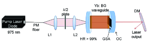
Fig.3 is the schematic of our cavity. We use a 50mm Yb:BG substrate with 1.6x1026m-3Yb3+ dopants and 2.03 refractive index as gain medium. The waveguide is inscribed by focusing the pulses, through a 0.4NA lens, 200m below the substrate surface, by a master oscillator power amplifier fiber laser (IMRA FCPA -Jewel D400) delivering 350fs pulses at 1047nm and 1MHz repetition rate. An automated x-y-z stage translates the sample, thus extending the positive index change at the laser focus to form a waveguide. Low insertion loss waveguides with symmetric cross-sections are realised using a multi-scan techniqueNasu_ol_2005 , inscribed with pulse energies50nJ. Previously, highly efficient continuous wave lasing was demonstrated from these, with top slope efficiency79%Mary_ol_2012 .
The pump source is a polarisation-maintaining fiber-coupled diode laser at 976nm, with 530mW maximum pump power, and an angle cleaved fiber to avoid back reflections. Two identical lenses with a 6.2nm focal length couple the pump light efficiently into the waveguide, and a half-wave plate varies the pump polarization. A dichroic mirror with 99% reflection from 1010-1200nm and 2% at the pump is the pump mirror. The mirrors are butt-coupled to either waveguide end using an index matching gel, which also reduces the parasitic Fresnel reflections at the interfacesBass_foh . A dichroic mirror separates the QML output from the residual pump light.
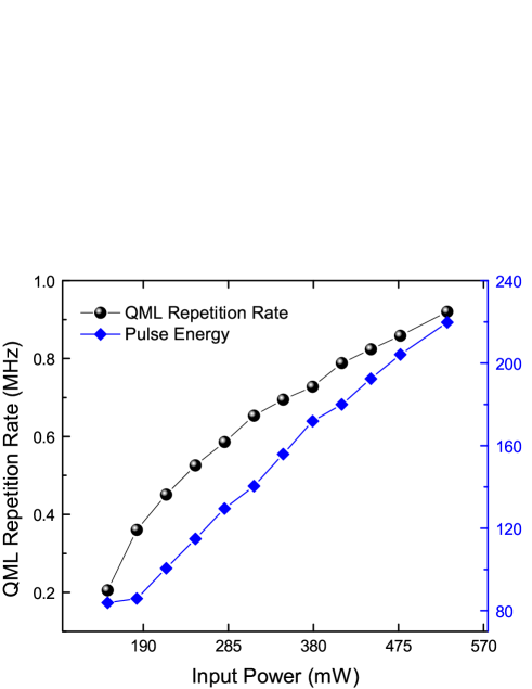
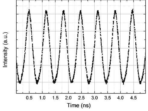
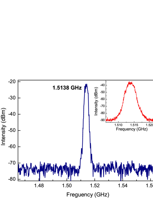
The laser operation initiates abruptly at a threshold pump power of 100mW in a self-starting QML regime. The cavity is optimized by adjusting the pump coupling efficiency, pump beam polarization, and GF-SA position. The mode area on the GF-SA is dictated by that of the waveguide. Using a fast photodiode and a wide-bandwidth oscilloscope, the initial QML repetition rate is measured as 200kHz, with 17mW average output power. Mode-locked pulses at a fundamental repetition rate of 1.514GHz, corresponding to the free spectral range of the cavity, are measured within the Q-switched envelope. Fig.4 shows the QML pulse repetition rate and energy evolution within a single Q-switched envelope. As the launch pump power is increased, the period between the Q-switched pulses reduces, indicating a tendency towards CW mode-locking. At the highest available pump power of 530mW, the Q-switching modulation has a frequency of 0.95MHz, and an average output power of 202mW, corresponding to a pulse energy of 220nJ. This is distributed along the mode-locked pulses existing within the Q-switch envelope. Fig.5 shows a constant mode-locked pulse train behaviour measured on a timescale of 500ps/div. Mode-locking at the fundamental repetition rate is also verified by measuring the rf spectra with a Rigol 1030 spectrum analyzer (Fig.6). The4.2MHz spectral width indicates no pure CW mode-lockingLinde_apb_1986 , as further shown in the inset of Fig.5.
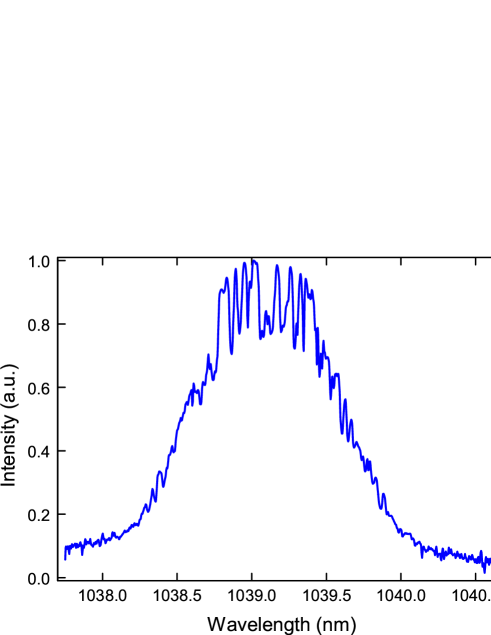
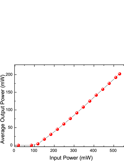
The optical spectrum is given in Fig.7. The spectral bandwidth, corresponding to a pump power of 530mW, is 1.1nm. With increasing pump, the spectral peak migrates slightly to longer wavelengths. For the maximum input pump power of 530mW, we have an average output power of 202mW. The average output power dependence on the pump is given in Fig.8. The QML waveguide laser has a high slope efficiency of 48%, and a 38% overall optical-to-optical conversion efficiency. Stable QML pulses are observed over24 hours, establishing the good quality of the GF-SA.
In conclusion, a monolithic waveguide laser with stable and efficient Q-switched mode-locking was demonstrated using a transferred graphene film to an output coupler. This is a robust, reliable, practical passive mode-locking element, with easy integration in a waveguide cavity.
We acknowledge funding from ERC Grant NANOPOTS, EPSRC Grant EP/G030480/1, a Royal Society Wolfson Research Merit Award, The Royal Academy of Engineering, Emmanuel College and King’s College, Cambridge.
References
- (1) T. Hasan, Z. Sun, F. Wang, F. Bonaccorso, P. H. Tan, A. G. Rozhin, and A. C. Ferrari, Adv. Mater. 21, 3874 (2009).
- (2) F. Bonaccorso, Z. Sun, T. Hasan, A. C. Ferrari, Nat. Phot. 4, 611 (2010).
- (3) Z. Sun, T. Hasan, A. C. Ferrari, Physica E 44, 1082 (2012).
- (4) D. Popa, Z. Sun, T. Hasan, F. Torrisi, F. Wang, A. C. Ferrari, Appl. Phys. Lett. 98, 073106 (2011).
- (5) D. Popa, Z. Sun, T. Hasan, W. B. Cho, F. Wang, F. Torrisi, A. C. Ferrari, Appl. Phys. Lett. 101, 153107 (2012).
- (6) Z. Sun, T. Hasan, F. Torrisi, D. Popa, G. Privitera, F. Wang, F. Bonaccorso, D. M. Basko, and A. C. Ferrari, ACS Nano 4, 803 (2010).
- (7) Z. Sun, D. Popa, T. Hasan, F. Torrisi, F. Wang, E. Kelleher, J. Travers, V. Nicolosi, and A. Ferrari, Nano Res. 3, 653 (2010).
- (8) M. Zhang, E. J. R. Kelleher, F. Torrisi, Z. Sun, T. Hasan, D. Popa, F. Wang, A. C. Ferrari, S. V. Popov, J. R. Taylor, Opt. Express 20, 25077 (2012).
- (9) J. Ma, G. Q. Xie, P. Lv, W. L. Gao, P. Yuan, L. J. Qian, H. H. Yu, H. J. Zhang, J. Y. Wang, D. Y.Tang, Opt. Lett. 37, 2085 (2012).
- (10) L. M. Zhao, D. Y. Tang, H. Zhang, X. Wu, Q. Bao, K. P. Loh, Opt. Lett. 35, 3622 (2010).
- (11) D. Popa, Z. Sun, F. Torrisi, T. Hasan, F. Wang, and A. C. Ferrari, Appl. Phys. Lett. 97, 203106 (2010).
- (12) F. Wang, A. G. Rozhin, V. Scardaci, Z. Sun, F. Hennrich, I. H. White, W. I. Milne, A. C. Ferrari, Nat. Nanotechnol. 3, 738 (2008).
- (13) G. Della Valle, R. Osellame, G. Galzerano, N. Chiodo, G. Cerullo, P. Laporta, and O. Svelto, Appl. Phys. Lett. 89, 231115 (2006).
- (14) S. J. Beecher, R. R. Thomson, N. D. Psaila, Z. Sun, T. Hasan, A. G. Rozhin, A. C. Ferrari, and A. K. Kar, Appl. Phys. Lett. 97, 111114 (2010).
- (15) A. A. Lagatsky, Z. Sun, T. S. Kulmala, R. S. Sundaram, S. Milana, F. Torrisi, O. L. Antipov, Y. Lee, J. H. Ahn, C. T. A. Brown, W. Sibbett, A. C. Ferrari, arXiv:1210.7042 (2012).
- (16) F. Bonaccorso, A. Lombardo, T. Hasan, Z. Sun, L. Colombo, A. C. Ferrari, arXiv:1212.3319 (2012)
- (17) O. Okhotnikov, A. Grudinin, and M. Pessa, New J. Phys. 6, 177 (2004).
- (18) U. Keller, and In E. Wolf, Progress in Optics (Elsevier, Amsterdam, 2004).
- (19) D. Brida, A. Tomadin, C. Manzoni, Y. J. Kim, A. Lombardo, S. Milana, R. R. Nair, K. S. Novoselov, A. C. Ferrari, G. Cerullo, and M. Polini, arXiv:1209.5729 (2012).
- (20) C. Hönninger, R. Paschotta, F. Morier-Genoud, M. Moser, U. Keller, J. Opt. Soc. Am. B 16, 46-56 (1999).
- (21) R. W. Boyd, Nonlinear Optics (Ac. Press, 2008).
- (22) S. H. Chung, E. Mazur, J. Biophot. 2, 557 (2009).
- (23) S. Nolte, C. Momma, H. Jacobs, A. Tünnermann,B. N. Chichkov, B. Wellegehausen, H. Welling, J. Opt. Soc. Am. B 14, 2716 (1997).
- (24) J. Mertz, Curr. Opin. Neurob. 14, 610 (2004).
- (25) S. A. Diddams, J. Opt. Soc. Am. B 27, B51-B62 (2010).
- (26) M. P. Moreno, S. S. Vianna, J. Opt. Soc. Am. B 28, 2066 (2011).
- (27) G. DellaValle, R. Osellame, P. Laporta, J. Opt. A 11, 013001 (2009).
- (28) C. Grivas, Progr. Quant. Electr. 35, 159 (2011).
- (29) A. Choudhary, A. A. Lagatsky, P. Kannan, W. Sibbett, C. T. A. Brown, and D. P. Shepherd, Opt. Lett. 37, 4416 (2012).
- (30) A. Martinez, K. Fuse, S. Yamashita, Appl. Phys. Lett. 99, 121107 (2011).
- (31) H. Yu, X. Chen, H. Zhang, X. Xu, X. Hu, Z. Wang, J. Wang, S. Zhuang, and M. Jiang, ACS Nano 4, 7582 (2010).
- (32) J. Liu, Y. G. Wang, Z. S. Qu, L. H. Zheng, L. B. Su, and J. Xu, Laser Phys. Lett. 9, 15 (2012).
- (33) C. Mattevi, G. Eda, S. Agnoli, S. Miller, K. A. Mkhoyan, O. Celik, D. Mastrogiovanni, G. Granozzi, E. Garfunkel, and M. Chhowalla, Adv. Funct. Mater. 19, 2577 (2009).
- (34) Y. Hernandez, V. Nicolosi, M. Lotya, F. M. Blighe, Z. Y. Sun, S. De, I. T. McGovern, B. Holland, M. Byrne, Y. K. Gun’Ko, J. J. Boland, P. Niraj, G. Duesberg, S. Krishnamurthy, R. Goodhue, J. Hutchison, V. Scardaci, A. C. Ferrari, J. N. Coleman, Nat. Nanotechnol. 3, 563 (2008).
- (35) T. Hasan, F. Torrisi, Z. Sun, D. Popa, V. Nicolosi, G. Privitera, F. Bonaccorso, and A. C. Ferrari, Phys. Status Solidi B 247, 2953 (2010).
- (36) A. C. Ferrari, J. C. Meyer, V. Scardaci, C. Casiraghi, M. Lazzeri, F. Mauri, S. Piscanec, D. Jiang, K. S. Novoselov, S. Roth, and A. K. Geim, Phys. Rev. Lett. 97, 187401 (2006).
- (37) A. C. Ferrari, J. Robertson, Phys. Rev. B 61, 14095 (2000).
- (38) C. Casiraghi, A. Hartschuh, H. Qian, S. Piscanec, C. Georgi, A. Fasoli, K. S. Novoselov, D. M. Basko,A. C. Ferrari, Nano Lett. 9, 1433 (2009).
- (39) A.C.Ferrari, J. Robertson, Phys. Rev. B 64, 075414 (2001).
- (40) S. Latil, V. Meunier, L. Henrard, Phys. Rev. B 76, 201402 (2007).
- (41) A. Das, S. Pisana, B. Chakraborty, S. Piscanec, S. K. Saha, U. V. Waghmare, K. S. Novoselov, H. R. Krishnamurthy, A. K. Geim, A. C. Ferrari, and A. K. Sood, Nat. Nano. 3, 210 (2008).
- (42) D. M. Basko, S. Piscanec, and A. C. Ferrari, Phys. Rev. B 80, 165413 (2009).
- (43) M. Lotya, Y. Hernandez, P. J. King, R. J. Smith, V. Nicolosi, L. S. Karlsson, F. M. Blighe, S. De, Z. Wang, I. T. McGovern, G. S. Duesberg, and J. N. Coleman, J. Am. Chem. Soc. 131, 3611 (2009).
- (44) V. G. Kravets, A. N. Grigorenko, R. R. Nair, P. Blake, S. Anissimova, K. S. Novoselov, and A. K. Geim, Phys. Rev. B 81, 155413 (2010).
- (45) K. F. Mak, M. Y. Sfeir, Y. Wu, C. H. Lui, J. A. Misewich, and T. F. Heinz, Phys. Rev. Lett. 101, 196405 (2008).
- (46) Z. Q. Li, E. A. Henriksen, Z. Jiang, Z. Hao, M. C. Martin, P. Kim, H. L. Stormer, and D. N. Basov, Nature Phys. 4, 532 (2008).
- (47) Y. Nasu, M. Kohtoku, Y. Hibino, Opt. Lett. 30, 723 (2005).
- (48) R. Mary, S. J. Beecher, G. Brown, R. R. Thomson, D. Jaque, S. Ohara, and A. K. Kar, Opt. Lett. 37, 1691 (2012).
- (49) M. Bass, E. W. Van Stryland, Fiber optics handbook: fiber, devices, and systems for optical communications (McGraw-Hill, 2002).
- (50) D. v. d. Linde, Appl. Phys. B 39, 201 (1986).