Three-qubit Grover’s algorithm using superconducting quantum interference devices in cavity-QED
Abstract
We present a scheme for the implementation of three-qubit Grover’s algorithm
using four-level superconducting quantum interference devices (SQUIDs)
coupled to a superconducting resonator. The scheme is based on resonant,
off-resonant interaction of the cavity field with SQUIDs and application of
classical microwave pulses. We show that adjustment of SQUID level spacings
during the gate operations, adiabatic passage, and second-order detuning are
not required that leads to faster implementation. We also show that the
marked state can be searched with high fidelity even in the presence of
unwanted off-resonant interactions, level decay, and cavity dissipation.
Keywords: Quantum phase gate; Grover’s algorithm; Superconducting quantum interference devices (SQUIDs)
I INTRODUCTION
The quantum algorithms work much more efficiently than their classical counter parts due to quantum superposition and quantum interference. For example, consider the search of an item in an unsorted database containing elements. Classical computation requires steps to carry out the search. However, Grover showed that search can be carried out with only steps grover ; farhi . Thus, Grover’s algorithm represents a quadratic advantage over its classical counterpart.
Grover’s algorithm has been realized using many physical systems like NMR iln , superconducting qubits lyan ; phyc and atom cavity QED systems pnas ; harg ; deng ; wlyang ; joshi . Superconducting qubit cavity QED is an attractive approach for quantum information processing due to their strong coupling limit in microwave cavity as compared to atoms in cavity QED cpyang ; cpyang2 ; wall . SQUIDs have attracted much attention among the superconducting qubits, due to their design flexibility, large-scale integration, and compatibility to conventional electronics hanx ; ich ; mooj . Recently, DiCarlo et al. demonstrated the implementation of two-qubit Grover and Deutsch-Jozsa algorithms Carlo and preparation and measurement of three-qubit entanglement reed using superconducting qubits.
The goal of this work is to implement three-qubit Grover’s algorithm using four-level SQUIDs in cavity-QED. We consider a three-qubit phase gate, that reduces the number of quantum gates typically required for the realization of Grover’s algorithm. Three-qubit Grover’s algorithm is probabilistic wlyang , as compared to two-qubit Grover’s algorithm. Therefore, to achieve high success probability, we have to implement basic searching iteration several times. Implementation of three-qubit Grover search is much more complex as compared to two-qubit case. In our scheme, two lowest energy levels and of each SQUID represent logical states. The scheme is based on resonant, off-resonant interaction of cavity field with transition of SQUID and application of resonant microwave pulses.
Our scheme does not require adjustment of SQUID level spacing during the implementation of Grover’s search iteration, thus, decoherence caused by the adjustment of level spacing is suppressed. We do not require identical coupling constants of each SQUID with the resonator and direct coupling between the levels and lap . Grover’s iteration time becomes faster due to resonant and off-resonant interactions as compared to second order detuning or adiabatic passage.
Grover’s iterations based on three-qubit quantum phase gate employed here, considerably simplify the implementation as compared to conventional gate decomposition method nielsen . More importantly, it reduces the possibility of error in comparison with a series of two-qubit gates. We also consider the effect of spontaneous decay rate from intermediate level and decay of cavity field during the implementation of Grover’s iterations.
II GROVER’S ALGORITHM
The basic idea of Grover’s algorithm is as follows; we prepare input basis states in superposition state by applying Walsh-Hadamard transformation. First we, invert phase of the desired basis state through unitary operator (called Oracle) and then invert all the basis states about the average. We consider the implementation of Grover’s algorithm in terms of quantum logic networks as shown in Fig. 1. Any quantum logical network can be constructed using quantum phase gates and single-qubit quantum gates. The single-qubit quantum gate for qubit can be written in Dirac notation as
| (1) |
For and , we have . Here is the Pauli rotation matrix whose function is to flip the state of qubit such that and For and , we have which transforms each qubit into superposition state i.e., and
The transformation for three-qubit quantum controlled phase gate can be expressed by
| (2) |
where , , and stand for basis or of the qubit and , , and are the Kroneker delta functions. Thus, three-qubit quantum phase gate induces a phase only when all three input qubit are in state . Three-qubit quantum phase gate operator for can be written in Dirac notation as
| (3) | |||||
The three-qubit controlled phase gate can be used instead of involving series of two-qubit gates. This method not only simplifies the implementation but also reduces the probability of error. Figure. 1 shows the circuit diagram of three-qubit Grover’s algorithm based on three-qubit phase gate and two-qubit gates zubairy ; zubairy2 . Consider that the initial state of three qubits is . Grover’s algorithm can be carried out using the following three steps:
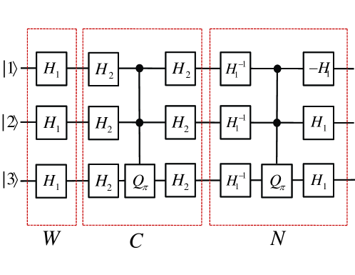
Part 1 (W): Apply Walsh-Hadamard transformation on each qubit. The resultant state is therefore given by
| (4) |
Part 2 (C): In this step, consider the unitary operator (called Oracle) which changes the sign of target state . The operator performs the unitary transformation which can be implemented using three-qubit phase gate and single-qubit gate as shown in Fig. 1. The sign change operators for eight possible target states are given by
| (5) |
Now Oracle applies one of operators on state given in Eq. (4) and changes the sign of target state. For example, our target state is , then by applying on state (4), we obtain the change of phase on target state i.e.,
| (6) |
Part 3 (N): In this step, our goal is to find out the marked state . This can be accomplished through inversion about mean using the operator . It is clear from Fig. 1 that the operator can be written in terms of single-qubit gate and three qubit quantum phase gate
| (7) |
The combined operator is called Grover’s operator. When is applied to initial state times, then the probability of searching target state becomes maximum farhi .
III Basic Theory
Here, we consider rf-SQUIDs as qubits that consist of a single Josephson junction enclosed by superconducting loop. The corresponding Hamiltonian is given by rouse
| (8) |
where and are junction capacitance and loop inductance, respectively. The conjugate variables of the system are magnetic flux threading the ring and total charge on capacitor. The static external flux applied to the ring is and is the Josephson coupling energy. Here, is critical current of Josephson junction and is the flux quantum.
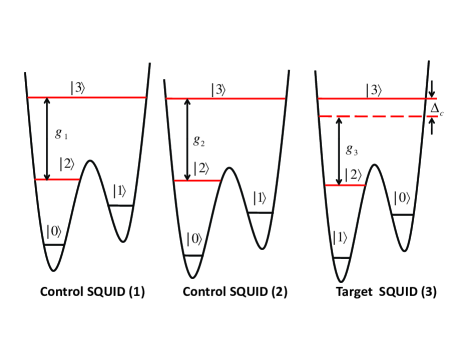
The SQUIDs are biased properly to achieve desired four-level structure as shown in Fig. 2 by varying the external flux w . The single-mode of the cavity field is resonant with transition of SQUIDs 1 and 2. The evolution of initial state and under the effect of Hamiltonian (8) can be written as w
| (9) |
where () is vacuum (single photon) state of the cavity field and () is the coupling constant between the cavity field and transition of the SQUID and .
The cavity field interacts off-resonantly with transition of SQUID 3 (i.e., as shown in Fig. 2. Here, is the detuning between transition frequency of SQUID 3, is the frequency of resonator and is coupling constant between resonator mode and transition. In the presence of single photon inside the cavity, the evolution of initial state and are given by w
| (10) |
It is clear that phase shifts and are induced to states and of SQUID 3, respectively. However, states and remain unchanged.
A classical microwave pulse resonant with () is applied to each SQUID. The evolution of states can be written as yang
| (11) |
where is the Rabi frequency between two levels and and is the phase associated with classical field. It may be mentioned that resonant interaction between pulse and SQUID can be carried out in a very short time by increasing the Rabi frequency of pulse.
IV Implementation of Grover’s algorithm
Three SQUIDs shown in Fig. 2 are initially prepared in state . For notation convenience, we denote ground level as and first excited state as for SQUID as shown in Fig. 2.
Part 1 (W): To accomplish part 1of Grover’s algorithm, we apply single-qubit gate to each SQUID as shown in Fig. 1. The single-qubit gate is carried out through two-step process that involves an auxiliary level via method described in Ref yh . We need two microwave pulses of different frequencies resonant to and transitions. The desired arbitrary single-qubit gate (See Eq. (1)) can be achieved by choosing a proper interaction time (i.e., ) and phase of classical microwave pulse resonance to transition. We achieve by choosing and as a result we obtain state given by Eq. (4).
Part 2 (C): In order to implement apply single-qubit gate by choosing and as shown in Fig. 1. Then apply three-qubit quantum controlled phase gate. The procedure for realizing the three-qubit controlled phase gate is described as follows:
Initially, cavity is in a vacuum state and levels and of each SQUID are not occupied.
Step 1. Apply microwave pulse (with and phase , where is pulse duration) resonant to transition of the SQUID to occupy level Cavity field interacts resonantly to the transition of SQUID for time interval such that the transformation is obtained. The overall step can be written as . However, the state remains unchanged.
Step 2. Apply microwave pulse (with and phase ) to the SQUID 1 while a microwave pulse (with and phase ) to the SQUID 2. As a result transformations for SQUID 1 while for SQUID 2 are obtained.
Step 3. After the above operation, when cavity is in a single photon state , only the level of SQUID 2 is populated. The cavity field interacts resonantly to transition of SQUID 2 for time We then obtain transformation while states , and, remain unchanged. Then apply microwave pulse (with and phase ) to SQUID 2 to transform state to . The overall step can be written as . However, states , and remain unchanged. The evolution of the system after above three steps is given by
| (12) |
It must be noted here that we have shown the evolution of only four initial possible states out of eight states (See Eq. (4)) since the evolution of other four states i.e., and is trivial.
Step 4. Apply microwave pulse with and phase to SQUID 3 to obtain transformation . After the above operation only level of SQUID (3) is populated, when cavity is in a single photon state. Now the cavity field interacts off-resonantly to transition of SQUID 3. It is clear from Eq. (10) that for , state changes to . However, states , and remain unchanged.
Step 5. Apply microwave pulse (with and phase ) to SQUID 3, as a result state transformation is obtained.
Step 6. Perform reverse of the operations mentioned in step 3. Apply microwave pulse (with and phase ) to SQUID 2. Wait for time given in step 3, during which cavity field interacts resonantly to transition of the SQUID 2. Over all transformation can easily be written as . However, states , and remain unchanged. The evolution of the system after applying steps 4-6 is given by
| (13) |
Step 7. Apply microwave pulse (with and phase ) to SQUID 2 while a microwave pulse (with and phase ) to SQUID 1. The transformations for SQUID 2 while for SQUID 1 are obtained.
Step 8. Now perform reverse operation of step 1. First wait for time interval during which resonator interacts resonantly to the transition of SQUID 1. Then apply microwave pulse (with and phase ) to SQUID 1. The overall step can easily be written as . However, state remains unchanged. After applying steps 7-8, the system evolves as
| (14) |
After the application of three-qubit phase gate, the state given by Eq. (4) evolves to
| (15) |
Next apply single-qubit gate i.e., which completes the part 2 (C) of the implementation scheme.
Part 3 (N): In order to implement operator , apply single-qubit gate , then apply three-qubit quantum controlled phase gate by repeating the above mentioned 8 steps. Finally, apply single-qubit Hadamard gate . It is clear that Grover’s operator for eight objects () can be implemented using four-level SQUIDs coupled to superconducting resonator.
It may be pointed out that in order to implement a three-qubit phase gate using conventional decomposition method, it requires twenty five basic gates, i.e., six two-qubit phase gates, twelve single-qubit Hadamard gates, and seven single-qubit phase shift gates nielsen . If we assume that the realization of each basic gate requires a one-step operation only, then twenty five steps are required for a three-qubit phase gate. Whereas in our scheme total number of eight steps are needed to implement three-qubit phase gate. As a result our proposed implementation scheme for Grover’s search algorithm which is based on three-qubit phase gate is faster than one based on two-qubit phase gate.
After performing the required gate operations for Grover’s algorithm, we need to readout the computational results. This can be done by jointly detecting the states of the three qubits Carlo ; reed . The readout for flux qubit can be done by measuring the Josephson inductance of a SQUID that is inductively coupled to the qubit lupas ; lupas2 ; lupas3 . There are some interesting schemes to perform joint dispersive readouts for superconducting qubits blais ; majer ; filip . The implementation of our scheme also requires such joint dispersive readout for three SQUIDs.
V Imperfections in implementation
Here, we discuss different types of imperfections which can arise during the implementation of Grover’s algorithm. The relevant parameters during the implementation are coupling constant decay rate of level and cavity decay rate We consider spontaneous decay from the intermediate level , during resonant interaction of cavity field with transition of SQUIDs 1 and 2. Here, we assume that under the condition that no photon from spontaneous emission is detected, the conditional Hamiltonian for the evolution of system is given by yh
| (16) |
The Hamiltonian given by Eq. (16) is valid as long as the decay rate of level is much smaller than The decay rate of SQUID 1 and 2 can affect the performance of three-qubit phase gate. Suppose each SQUID is initially prepare in generic state Now the state of three qubits becomes where the coefficients and , satisfy the normalization condition. If we consider , then the state of the system after phase gate operation becomes However, if the decay of level is included during phase gate then the expression for becomes rather complex, therefore it is not reproduced here. The fidelity of three-qubit phase gate is given by
| (17) | |||||
| (18) |
Here, with , , and In order to realize the effects of decay on the performance of three-qubit phase gate, average fidelity over all possible three-qubit initial states is calculated using the following:
| (19) |
After carrying out integration, we obtain
| (20) |
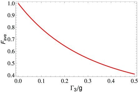
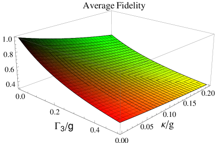
Next, we show the plots of average fidelity as a function of in Fig. 3. It can easily be verified that for one has which leads to It is clear from Fig. 3 that average fidelity decreases due to the increase in the cavity decay rate. We also calculate the success probability of three-qubit phase gate which is given by
| (21) | |||||
If we consider then corresponding success probability of three-qubit phase gate reduces to
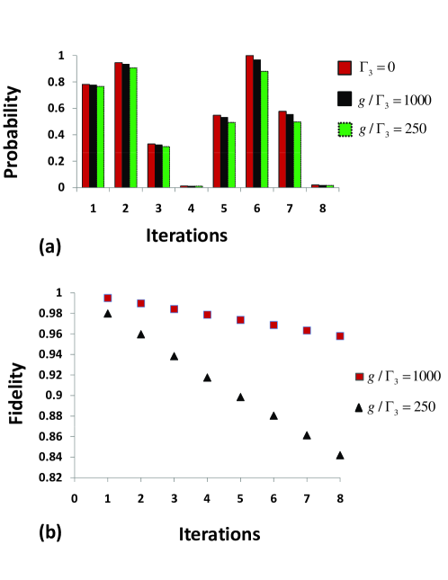
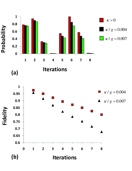
We take into account success rate of three-qubit phase gate (Eq. 21) and Grover search itself. We consider without loss of generality and perform simulation for finding the target state for (ideal case), , and Here, we consider the success probability for target state as shown in Fig. 4(a). It is clear from Fig. 4(a) that success rate becomes closer to the ideal case when decay rate is sufficiently smaller than coupling constant i.e., Typical decoherence rate for SQUID is of the order while coupling constant can be achieved upto han . This shows that for these parameters, three-qubit controlled phase gate and Grover’s iterations can be performed with high fidelity. Probability of success is highest at iteration for ideal case. However, we should prefer iteration in the presence of dissipation because it has the highest value of fidelity. The effect of level decay on the fidelity of search state during iteration is shown in Fig. 4(b). It is clear from Fig. 4(b) that the fidelity of state to be searched decreases much rapidly for the case of larger decay rate as compared to smaller decay rate as the number of iterations increase.
Next we consider the effects of cavity decay during the implementation of Grover’s algorithm. During the implementation of three-qubit phase gate (Sec. IV), transition of SQUID 1 from level to would result in the emission of one photon (See step in Sec. IV). Then transition of SQUID 2 from level to would absorb this photon with unit probability in step and vice versa for step and In the absence of cavity decay the occupation probability of level and of SQUID 1 and 2 should be exactly one. However, if cavity relaxation is taken into account, then the occupation probabilities are expected to decay exponentially. Under the assumption that no photon actually leaks out during implementation time, we can write the conditional Hamiltonian as wlyang
| (22) |
where, is the cavity decay rate and is the coupling constant. For we only need to focus on time evolution of the system governed by conditional Hamiltonian (Eq. (22)) under the assumption of strong coupling limit. The fidelity and corresponding success probabilities for three-qubit phase gate can easily be obtained, which are given by
| (23) |
and
| (24) |
For , we have The success probability of target state for ideal case and in the presence of cavity decay is shown in Fig. 5(a). It can be seen that the probability of finding target state decreases in the presence of cavity decay rate. The effects of cavity decay rate on fidelity of Grover’s search iteration is also shown in Fig. 5(b). It is clear from Fig. 5(b) that the fidelity of Grover’s search decreases as a function of iterations much rapidly for higher cavity decay rate.
We have separately discussed the effects on fidelity from spontaneous decay and cavity decay, however, in a general case the system involves both these decays. Thus we also consider the effect of these decays simultaneously. The results of our numerical simulation for corresponding average fidelity are shown in Fig. 6. It is clear from Figs. 4-6 that our proposed Grover’s iterations can be performed with high success probability and fidelity as long as cavity decay rate and decay rate of the intermediate level is small enough. The typical values of cavity decay rate is () han . It may be mentioned that more rigorous analysis is required for the case of very low resonators.
VI DISCUSSION AND CONCLUSION
We have discussed the implementation of 3-qubit Grover’s algorithm using 4-level SQUIDs subjected to quantized and classical microwave fields. Grover’s algorithm involves three-qubit phase gates and single-qubit gates. Here, we briefly estimate the total operational time for three-qubit controlled phase gate. The total implementation time is the sum of all interaction times involved in three-qubit controlled phase gate operation i.e., On substituting the values of interaction times given in Sec. we obtain
| (25) |
Here, we consider without loss of generality which is the same as given in Ref han . Choosing , , the operational time for three-qubit phase gate comes out to be . The operation time for single-qubit gate is about yh which can be applied to each qubit, simultaneously. Therefore, the estimated time for the implementation of three-qubit Grover algorithm performing two iterations is approximately .
We have considered the effect of decay for level under the assumption that the decay rate of level is much smaller then level . The typical values of the decay time for levels and are and 0.16 ms as discussed in Ref. han . During the steps 1,2, and 3 in phase gate operations level of SQUIDs 1 and 2 is occupied through the application of SQUID-pulse resonant interaction and SQUID-resonator resonant interaction as discussed in Sec. IV. Operation time for SQUID 1 and for SQUID 2, in these steps is equal to and , respectively, which can be shortened by increasing the Rabi frequency and coupling constants and . For the typical choice of parameters as given in Ref han , we have , which is much shorter than . The SQUIDs can also be designed to have long relaxation time for level . Thus decoherence due to relaxation of level can be negligibly small. As far as the decay of level is concerned, it may be pointed out that in our scheme direct coupling between levels and is not needed. The potential barrier between levels and can also be adjusted such that decay of level is negligibly small lap ; han . Therefore, storage time of each qubit can be made much longer.
When levels and are manipulated by microwave pulses, resonant interaction between cavity field mode and transition of each control SQUID is unwanted. This effect can be minimized by setting the condition for SQUIDs 1 and 2.
During the application of microwave pulse, off-resonant interaction of cavity field with transition, in the presence of single photon inside the cavity is unwanted. It induces an unwanted phase which can effect the performance of the desired gate. This effect can be negligible under the condition for SQUID . However, if this effect is included during the steps and for three-qubit phase gate, then the corresponding fidelity can easily be obtained. Here, we do not present the expression for owing to its complexity, however the fidelity is given by
| (26) |
where, , with and The average fidelity over all possible initial states is given by
| (27) | |||||
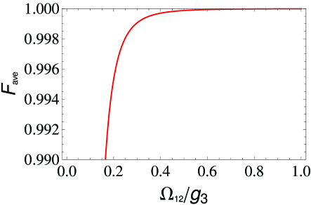
If off-resonant interaction during step and is not considered, then we have and which leads to The plot of the average fidelity as a function of Rabi frequency is shown in Fig. 7. We choose for this plot. It can be seen that the average fidelity increases as a function of Rabi frequency applied to target SQUID. It is clear from Fig. 7 that for , we have
When slowly changing Rabi frequencies are applied to satisfy the adiabatic passage, gate times becomes slow i.e., of the order of 1 ms to a few microseconds wang . However, in our scheme we do not require slowly changing Rabi frequency during the implementation of three-qubit phase gate, thus gate is significantly faster i.e., of the order of 13ns. The fast pulses may introduce new imperfections, for example, accurately designing of the duration of pulses might not be easy. It may be mentioned here that adiabatic process is not always slow as an interesting proposal based on controllable Stark-chirped rapid adiabatic passage has been proposed in a recent study lfw .
Here, we would like to mention that the physical implementation of three-qubit Grover’s algorithm in cavity quantum electrodynamics (QED) has been proposed in a recent study by Yang et al wlyang . The scheme is based upon the resonant interaction of three Rydberg atoms initially prepared in a coherent superposition state traversing through a single-mode microwave cavity. As compared to the flying qubits, here we have considered stationary qubits defined through two lowest level of four level SQUIDs. Our scheme is based on the generation and absorption of single photon in high Q cavity using SQUIDs. The generation of single microwave photon in superconducting qubit have been reported, experimentally in some recent studies et al. photon ; photon2 .
In conclusion, we have proposed a scheme for the realization of three-qubit Grover’s algorithm based on three-qubit phase gate using four-level SQUIDs coupled to a single-mode superconducting resonator. In this proposal, adjustment of level spacing during the operation, slowly changing Rabi frequencies (to satisfy adiabatic passage), and the use of second-order detuning (to achieve off-resonance Raman coupling between two relevant levels) are not required. Thus, implementation time is significantly faster and has operation time of the order of nanoseconds. The coupling constants of each SQUID with the resonator are different. Thus, an unavoidable non-uniformity in device parameters can be accommodated. We consider the effect of imperfections in the system which include the decay of the cavity field and the relevant level. We also incorporate the influence of unwanted off-resonant interaction during the gate implementation. Our results show that the marked state can be searched with high fidelity even in the presence of imperfections in the system which is quite interesting.
References
- (1) Grover, L. K.: Quantum Mechanics Helps in Searching for a Needle in a Haystack. Phys. Rev. Lett. 79(2), 325-328 (1997).
- (2) Farhi, E., Gutmann, S.: Analog analogue of a digital quantum computation. Phys. Rev. A 57(4), 2403-2406 (1998).
- (3) Chuang, I. L., Gershenfeld, N., Kubinec, M.: Experimental Implementation of Fast Quantum Searching. Phys. Rev. Lett. 80(15), 3408-3411 (1998).
- (4) Yan, L., Ping, D., Zheng-Yuan, X., Zhuo-Liang, C.: Quantum search via superconducting quantum interference devices in a cavity. Chin. Phys. 16(12), 3601-3604 (2007).
- (5) Zheng, X. -H., Dong P., Xue, Z. -Y., Cao, Z-L.: Implementation of the Grover search algorithm with Josephson charge qubits. Physica C 453(1-2), 76-79 (2007).
- (6) Scully, M. O., Zubairy, M. S.: Quantum optical implementation of Grover’s algorithm. Proc. Natl. Acad. Sci. USA 98(17), 9490-9493 (2001).
- (7) Yamaguchi, F., Milman, P., Brune, M., Raimond, J. M., Haroche, S.: Quantum search with two-atom collisions in cavity QED. Phys. Rev. A 66(1), 010302 (2002);
- (8) Deng, Z. J., Feng, M., Gao, K. L.:Simple scheme for the two-qubit Grover search in cavity QED. Phys. Rev. A 72(3), 034306 (2005).
- (9) Yang, W. L., Chen, C. Y., Feng, M.: Implementation of three-qubit Grover search in cavity quantum electrodynamics. Phys. Rev. A 76(5), 054301 (2007).
- (10) Joshi, A., Xiao, M.: Three-qubit quantum-gate operation in a cavity QED system. Phys. Rev. A 74(5), 052318 (2006).
- (11) Yang, C. P., Chu, Shih-I., Han, S.: Quantum Information Transfer and Entanglement with SQUID Qubits in Cavity QED: A Dark-State Scheme with Tolerance for Nonuniform Device Parameter. Phys. Rev. Lett. 92(11), 117902 (2004);
- (12) Leek, P. J., Filipp, S., Maurer, P., Baur, M., Bianchetti, R., Fink, J. M., Göppl, M., Steffen, L., Wallraff, A.: Using sideband transitions for two-qubit operations in superconducting circuits. Phys. Rev. B 79(18), 180511(R) (2009).
- (13) Wallraff, A., Schuster, D. I., Blais, A., Frunzio, L., Huang, R.-S., Majer, J., Kumar, S., Girvin, S. M., Schoelkopf, R. J.:Strong coupling of a single photon to a superconducting qubit using circuit quantum electrodynamics. Nature (London) 431, 162-167 (2004).
- (14) Yu, Y., Han, S., Chu, X., Chu, S. -I., Wang, Z.: Coherent Temporal Oscillations of Macroscopic Quantum States in a Josephson Junction. Science 296, 889-892 (2002).
- (15) Chiorescu, I. et al.: Coherent dynamics of a flux qubit coupled to a harmonic oscillator. Nature (London) 431, 159-162 (2004).
- (16) Majer, J. B., Paauw, F. G.,ter Haar, A. C. J., Harmans, C. J. P. M., Mooij, J. E.: Spectroscopy on Two Coupled Superconducting Flux Qubits. Phys. Rev. Lett. 94(9), 090501 (2005).
- (17) DiCarlo, L., Chow, J. M., Gambetta, J. M., Bishop, L. S., Johnson, B. R., Schuster, D. I., Majer, J., Blais, A., Frunzio, L., Girvin, S. M., Schoelkopf, R. J.: Demonstration of two-qubit algorithms with a superconducting quantum processor. Nature, 460, 240-244 (2009).
- (18) DiCarlo, L., Reed, M. D., Sun, L., Johnson, B. R., Chow, J. M., Gambetta, J. M., Frunzio, L., Girvin, S. M., Devoret, M. H., and Schoelkopf, R. J.: Preparation and measurement of three-qubit entanglement in a superconducting circuit. Nature 467, 574-578 (2010).
- (19) Han, S., Lapointe, J., Lukens, J. E.: Single-Electron Tunneling and Mesoscopic Devices. Vol. 31, pp. 219 Springer-Verlag, Berlin, (1991).
- (20) Nielsen, M. A., Chuang, I. I.: Quantum Computing and Quantum Information. p-182, Cambridge University Press UK (2000).
- (21) diao, Z., Zubairy, M. S., Chen, G.: A Quantum Circuit Design for Grover’s Algorithm. Z. Naturforsch., A: Phys. Sci. 57a 701-708 (2002);
- (22) Zubairy, M. S., Matsko, A. B., Scully, M. O.: Resonant enhancement of high-order optical nonlinearities based on atomic coherence. Phys. Rev. A 65(4), 043804 (2002).
- (23) Han, S., Rouse, R., Lukens, J. E.: Generation of a Population Inversion between Quantum States of a Macroscopic Variable. Phys. Rev. Lett. 76(18), 3404-3407 (1996).
- (24) He, Xiao-Ling., Yang, C.P., Li, S., Luo, J. Y., Han, S.: Quantum logical gates with four-level superconducting quantum interference devices coupled to a superconducting resonator. Phys. Rev. A 82(2),024301 (2010).
- (25) Yang, C. P., Chu, Shih-I., Han, S.: Possible realization of entanglement, logical gates, and quantum-information transfer with superconducting-quantum-interference-device qubits in cavity QED. Phys. Rev. A 67(4), 042311 (2003).
- (26) Yang, C. P., Han, S.: Rotation gate for a three-level superconducting quantum interference device qubit with resonant interaction. Phys. Rev. A 74(4), 044302 (2006).
- (27) Lupascu, A., Verwijs, C. J. M., Schouten, R. N., Harmans, C. J. P. M., Mooij, J. E.: Nondestructive Readout for a Superconducting Flux Qubit. Phys. Rev. Lett. 93(17),177006 (2004);
- (28) Johnson, J. E., Hoskinson, E. M., Macklin, C., Slichter, D. H., Siddiqi, I., Clarke, J.: Dispersive readout of a flux qubit at the single-photon level. Phys. Rev. B 84(22), 220503 (R) (2011);
- (29) JJohnson, J. E., Macklin, C., Slichter, D. H., Vijay, R., Weingarten, E. B., Clarke, J., Siddiqi, I.: Heralded State Preparation in a Superconducting Qubit. Phys. Rev. Lett. 109(5), 050506 (2012).
- (30) Blais, A., Huang, R. -S., Wallraff, A., Girvin, S. M., Schoelkopf, R. J.: Cavity quantum electrodynamics for superconducting electrical circuits: An architecture for quantum computation. Phys. Rev. A 69(6), 062320 (2004).
- (31) J. Majer et al.,: Coupling superconducting qubits via a cavity bus. Nature 449, 443-447 (2007).
- (32) Filipp, S., Maurer, P., Leek, P. J., Baur, M., Bianchetti, R., Fink, J. M., Göppl, M., Steffen, L., Gambetta, J. M., Blais, A., Wallraff, A.: Two-Qubit State Tomography Using a Joint Dispersive Readout. Phys. Rev. Lett. 102(20), 200402 (2009).
- (33) Yang, C. P., Han, S.: Realization of an n-qubit controlled-U gate with superconducting quantum interference devices or atoms in cavity QED. Phys. Rev. A 73(3), 032317 (2006).
- (34) Zhang, P., Wang, Z. D., Sun, J. D., Sun, C. P.: Holonomic quantum computation using rf superconducting quantum interference devices coupled through a microwave cavity. Phys. Rev. A 71(4), 042301 (2005).
- (35) Wei, L. F., Johansson, J. R., Cen, L. X., Ashab, S., Nori, F.: Controllable Coherent Population Transfers in Superconducting Qubits for Quantum Computing. Phys. Rev. Lett. 100(11), 113601 (2008).
- (36) Houck, A. A., Schuster, D. I., Gambetta, J. M., Schreier, J. A., Johnson, B. R., Chow, J. M., Frunzio, L., Majer, J., Devoret, M. H., Girvin, S. M., Schoelkopf, R. J.: Nature 449, 328-331 (2007);
- (37) Wang, H., Hofheinz, M., Ansmann, M., Bialczak, R. C., Lucero, E., Neeley, M., O’Connell, A. D., Sank, D., Wenner, J., Cleland, A. N., Martinis, J. M.: Measurement of the Decay of Fock States in a Superconducting Quantum Circuit. Phys. Rev. Lett. 101(24), 240401 (2008).