The design, construction and performance of the MICE target
Abstract
The pion-production target that serves the MICE Muon Beam consists of a titanium cylinder that is dipped into the halo of the ISIS proton beam. The design and construction of the MICE target system are described along with the quality-assurance procedures, electromagnetic drive and control systems, the readout electronics, and the data-acquisition system. The performance of the target is presented together with the particle rates delivered to the MICE Muon Beam. Finally, the beam loss in ISIS generated by the operation of the target is evaluated as a function of the particle rate, and the operating parameters of the target are derived.
keywords:
Accelerator applications; Targets; Instrumentation for particle accelerators and storage rings; Control and monitor systems online; Overall mechanics designsIC/HEP/12-07
RAL-P-2012-007
1 Introduction
Muon storage rings have been proposed for use as sources of intense high-energy neutrino beams in a Neutrino Factory [1] and as the basis for multi-TeV lepton-antilepton colliding-beam facilities [2]. To optimise the performance of such facilities requires the phase-space compression (cooling) of the muon beam prior to acceleration and storage. The short muon-lifetime makes it impossible to employ traditional techniques to cool the beam while maintaining the muon-beam intensity. Ionisation cooling, a process in which the muon beam is passed through a series of liquid-hydrogen absorbers interspersed with accelerating RF cavities, is the technique proposed to cool the beam. The international Muon Ionisation Cooling Experiment (MICE) will provide an engineering demonstration of the ionisation-cooling technique and will allow the factors affecting the performance of ionisation-cooling channels to be investigated in detail [3]. Muon beams of momenta between 140 MeV/c and 240 MeV/c, with normalised emittances between 2 mm and 10 mm, will be provided by a purpose-built beam line on the 800 MeV proton synchrotron, ISIS [4], at the Rutherford Appleton Laboratory [5].
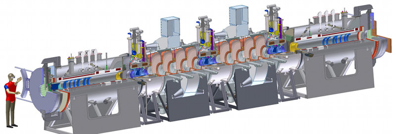
MICE is a single-particle experiment in which the position and momentum of each muon is measured before it enters the MICE cooling channel and once again after it has left (see figure 1) [6]. The MICE cooling channel, which is based on one lattice cell of the cooling channel described in [7], comprises three 20 volumes of liquid hydrogen and two sets of four 201 MHz accelerating cavities. Beam transport is achieved by means of a series of superconducting solenoids. A particle-identification (PID) system (scintillator time-of-flight hodoscopes TOF0 and TOF1 and threshold Cherenkov counters CKOVa and CKOVb) upstream of the cooling channel allows a pure muon beam to be selected. Downstream of the cooling channel, a final hodoscope (TOF2) and a calorimeter system allow muon decays to be identified. The calorimeter is composed of a KLOE-like lead-scintillator section (KL) followed by a fully active scintillator detector (the electron-muon ranger, EMR) in which the muons are brought to rest. For a full description of the experiment see [6].
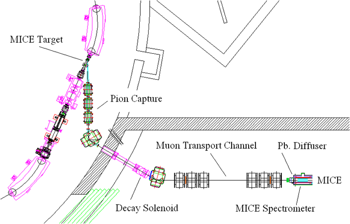
A schematic diagram of the MICE Muon Beam is shown in figure 2 [8]. A cylindrical target is dipped into the edge of the circulating proton beam. The depth at which the target is dipped into the proton beam is characterised by the ‘beam centre distance’ (BCD) which is defined to be the distance from the tip of the target to the proton-beam axis at the target’s maximum excursion into the beam. Pions produced in the target are captured by a quadrupole triplet and transported to a dipole magnet by which the pion momentum is selected. A 5 T super-conducting ‘decay’ solenoid follows the dipole. The additional pion path-length in the decay solenoid increases the muon-production efficiency. Following the solenoid, a second dipole is used to select the muon momentum and the beam is transported to MICE using a pair of large-aperture quadrupole triplets.
This paper is organised as follows. The requirements for the target system and an overview of its design are presented in section 2. Section 3 describes the design of the linear motor. The mechanical design of the target mechanism and the mechanical interface to the ISIS accelerator is presented in section 4. Section 5 describes the optical position-measurement system, the power electronics used to drive the linear motor is described in section 6 and the control system in section 7. The performance of the system, the particle rate delivered for the MICE Muon Beam and the beam losses induced in ISIS are presented in section 8. Finally, a summary is given in section 9.
2 Requirements and overview
The ISIS synchrotron [4] operates on a basic cycle of 50 Hz. Protons are injected with a kinetic energy of 70 MeV and accelerated to 800 MeV over a period of 10 ms prior to extraction. In the following 10 ms, the currents in the focusing and bending magnets are reduced to their initial values, ready for the next pulse of protons to be injected and accelerated.
MICE operation is parasitic to the functioning of ISIS and must cause minimal disruption to its principal function as a spallation neutron source. On selected pulses, the MICE target is caused to dip into the outer low-density halo of the proton beam just before extraction. Pions produced in the target emerge through a thin window in the ISIS vacuum system in the direction of the MICE muon beam line. On injection, the proton beam effectively fills the beam pipe. At the location of the MICE target, the beam has a vertical radius of mm. During acceleration, the beam shrinks to a radius of about 48 mm. To produce the required muon flux, the target must enter the beam by at least 5 mm, so a minimum travel of 24 mm is needed. (In practice, the exact position of the edge of the beam and the intensity of the halo show long-term variations. The position of the target at maximum insertion must therefore be controlled.) The target must be outside the beam envelope for the first 8 ms of the machine cycle, only entering the beam for the last 1 to 2 ms before extraction, when the protons are close to their maximum energy. The exact time of insertion must also be controllable.
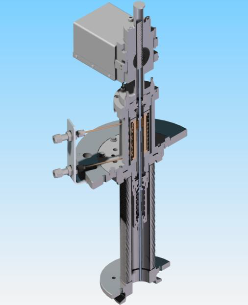
In order to meet the demands described above, a linear electromagnetic drive was implemented to move the target vertically into the beam from above. The technical challenges are considerable. The mechanism must be extremely reliable, to avoid disrupting normal accelerator operation. It must provide an acceleration of the order of 780 ms-2 so that the target overtakes the shrinking beam envelope and is removed before the next injection. Operation must be precise and reproducible, both in position and timing relative to the beam cycle. The mechanism must operate within a high radiation environment, and all moving parts must use materials compatible with the stringent constraints of the accelerator’s high-vacuum system. In case of any failure of the target mechanism, it must be possible to separate it both mechanically and in terms of vacuum from the synchrotron.
The complete target mechanism, described in detail in this paper, consists of a number of sub-assemblies.
-
•
The linear electromagnetic drive assembly, which contains:
-
–
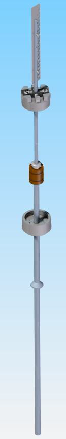
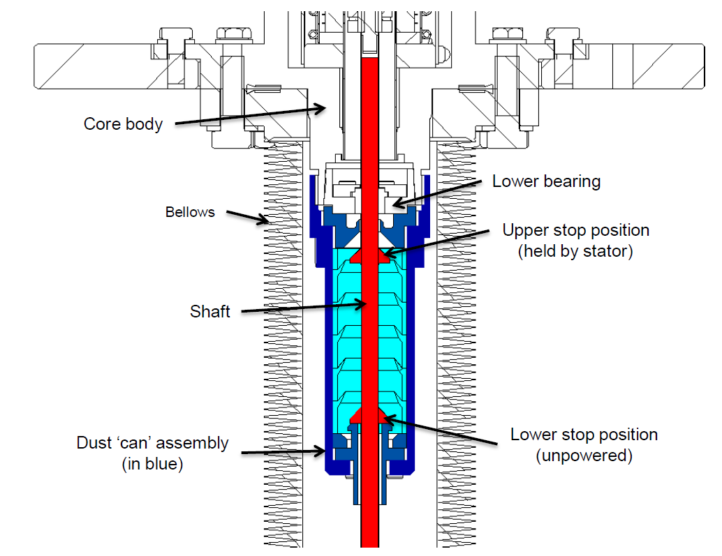
The shaft, forming the target at its lower end and carrying a set of fixed permanent magnets, an optical readout vane at its upper end and a stop to prevent the magnets falling from inside the coils in the absence of power;
-
–
A pair of bearings to support, guide and align the shaft;
-
–
The stator, consisting of stationary coils with a water cooling system;
-
–
A central steel tube forming a vacuum barrier between the target shaft and the stationary coil unit;
-
–
An optical readout enclosure, with sapphire windows.
-
–
-
•
The mechanical support assembly, which contains:
-
–
Flanges to provide accurate location of the stator and bearings;
-
–
Conflat seals, to ensure the integrity of the vacuum system.
-
–
-
•
The mechanical and vacuum isolation system, to allow the unpowered target to be raised out of the beam, and the target vacuum to be separated from the accelerator vacuum. This contains:
-
–
A structural frame, carrying the weight of the target assembly;
-
–
A jacking unit and support structure with motorised screw-jack allowing a vertical travel of approximately 200 mm;
-
–
Centralising units and guide rods that guarantee the target returns to its predefined position when lowered into its operating position;
-
–
Edge-welded bellows, to allow relative movement of the components under vacuum;
-
–
A vacuum gate valve to isolate the vacuum systems.
-
–
3 Linear motor
A linear actuator was chosen as the most appropriate mechanism to drive the target into the beam. This implementation does not require any moving parts to cross the vacuum chamber walls, and can be realised without the need for lubricated bearings. For most of the duty cycle, the actuator is only required to exert a small force on the target, to keep it levitated out of the beam. At the appropriate time, a large accelerating force is required over a short period to accelerate the target into and out of the beam and then bring it to rest at its levitated holding position. For this short period, high currents can be employed.
The motor must be of a permanent magnet, brush-less design, as the high acceleration and large travel of the motor rule out the placing of coils on the moving parts. The integration of permanent magnets into the moving assembly removes the need for electrical contacts between the stator and the moving parts, simplifying the interface between the motor and the ISIS vacuum. The magnets on the moving components interact with the field produced by a set of stationary coils in the stator body. These coils are outside the ISIS vacuum, directly wired to the driving electronics. Positioning outside the vacuum also allows the use of a water cooling circuit to remove the energy deposited by Joule heating of the coils.
The initial design of the linear motor was based on studies performed by an electrical engineer specialising in motor design, and outlined in [9]. The important constraints were to maximise the accelerating force while minimising the mass of the moving components. The mass of the magnetic materials thus form a significant fraction of the total mass. Different magnet and coil topologies were investigated, and the resulting design is documented in the following sections.
3.1 Electromagnetic design
Analysis of ISIS beam properties indicated that a peak acceleration of 780 m s-2 would give sufficient headroom for the target to achieve an appropriate interception with the beam given various beam conditions and a deep target actuation. The low mass of material required for interaction with the beam implies that the mass of the moving part of the motor (or “shuttle”) must be dominated by that of the permanent magnet assembly and any mechanical linkages. A design was therefore required which maximised the electromagnetic force while minimising the mass, with the goal of a specific force equal to 780 N kg-1 for reasonable assumptions of motor geometry and location. To achieve the highest magnetic loading, sintered neodymium-iron-boron magnets were chosen for the shuttle, as these have the greatest field strength and best strength-to-mass ratio. A bank of appropriately energised coils interact with the field of the magnets to drive the shuttle. Soft magnetic core material was considered for the stator, but this was not found to lead to any advantage, due to the small size of the motor and the fact that magnetic material would be saturated [9]. This was exacerbated by the significant “air-gap” between the permanent magnets (inside the vacuum chamber) and coils (outside), actually filled by vacuum and non-magnetic vacuum tube.
Two magnetic topologies were considered for the shuttle, and compared using 2-D axisymmetric modelling. Multi-pole radially magnetised discs attached to a central soft magnetic core were found to provide a more efficient device than axially magnetised discs separated by pole pieces. The radial design is also less prone to demagnetisation [9]. The exact geometry was then improved by iterative finite element studies. Test results from a prototype motor were used to validate the design.
3.2 Stator
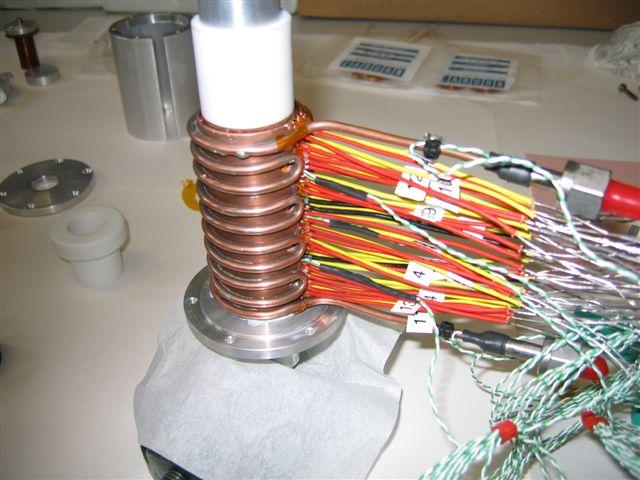
The stator, which is cylindrical in shape, contains a set of flat coils mounted around a thin-walled steel tube. After winding, each coil is impregnated with insulating varnish to form a stable compact unit. During assembly six 25 m copper shims are sandwiched between each pair of coils to facilitate heat conduction out of the coil stack. The addition of the copper shims gives a coil pitch of 3 mm. Connecting leads from the coils are led radially outwards. Three thermocouples are inserted between three pairs of coils to enable the temperature of the coil stack to be monitored. A coiled copper tube soldered onto a solid copper jacket is placed around the coils and is in contact with the copper shims. This carries the cooling water, the temperature of which is monitored at either end with two more thermocouples. The entire assembly is inserted into an aluminium outer cylinder, the stator body, with the insulated copper wires and the cooling pipes emerging through a slit in the side. The individual coils are wired up at terminal blocks placed external to the stator body.
3.2.1 Coils
The stator contains twenty-four identical coils that are stacked vertically and numbered one to twenty four starting from the top of the stator. The stator coils are responsible for interacting with the permanent magnets on the shaft both to levitate the target shaft when the target is being held out of the ISIS beam and to produce the accelerating force when the target needs to be inserted into the beam. (A motorised jacking platform is used to raise the target from the beam when not in use, as described in section 4.5.)
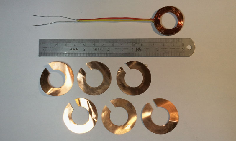
Each coil is composed of thirty six turns of 0.56 mm polyester-imide enamelled copper wire, over-coated with a polyamide-imide resin. This yields a high temperature winding wire that is rated to 200 operation[10]. These coils are wound on an 18.1 mm diameter former, each coil having a depth of 2.850.1 mm. Coils outside this tolerance are rejected due to the limited space between coils and the required pitch of 3 mm. The clearance of 0.15 mm between the coils is used to insert thin copper shims which act as heat sinks. After winding, the outer diameter of the coils is 30 mm. Each coil is double dipped into a varnish that seals the windings and provides additional electrical insulation[11]. Each coil is tested to 1 kV before being built into a stator. A photograph of a finished coil and some of the inter-coil copper shims is shown in figure 3. The copper shims provide a thermal path between the coils and the cooling jacket. The inner diameter of the shims is 19 mm and the outer diameter 36 mm. The shims are split to reduce eddy-current losses.
3.2.2 Stator Bore
A thin-walled non-magnetic stainless steel tube passing through the centre of the coils forms the stator bore. It provides isolation between the stator body and the ISIS vacuum and ensures the mechanical alignment of the coil stack. The nominal wall thickness of 0.5 mm is reduced to 0.3 mm where it passes through the coils. The reduction in magnetic field strength within the bore caused by the stainless steel tube was estimated to be 1%. The stainless steel tube is insulated from the coil stack using three layers of self-adhesive kapton tape.
3.2.3 Cooling Jacket
The cooling of the stator is extremely important as the rate of heat transfer from the coils to the cooling water ultimately limits the maximum rate at which the target can be actuated. Typically, when the stator is levitating the shaft out of the beam, the power consumption is 30 W. Every time the target is actuated an additional heat load of 400 J is deposited in the stator coils. The coils are small and therefore the heat capacity of the coil stack is correspondingly low. Without any heat-sink the coils would rise in temperature by 5 with every actuation. Therefore, if this heat is not removed quickly, repeated actuation of the stator will rapidly result in the temperature of the coils rising above their maximum rated working temperature of 200 .
Unfortunately, the permanent magnets that are attached to the shaft will not operate up to this temperature without there being a serious risk of demagnetisation. The exact maximum safe operating temperature is hard to determine, as the Curie temperature is field dependent. There is also some evidence that the risk of demagnetisation at elevated temperatures is accentuated when running permanent magnets in a radioactive environment[12]. Running the stator for extended periods has demonstrated that coil temperatures of 80–90 do not lead to demagnetisation.
A cooling circuit is required to remove heat from the coil stack. This consists of an external, water-cooled, split cylindrical copper jacket. The jacket has a thin-bore, copper cooling tube soldered onto its outer surface through which a flow of water can be maintained. This is illustrated in figure 4.
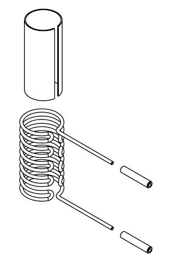
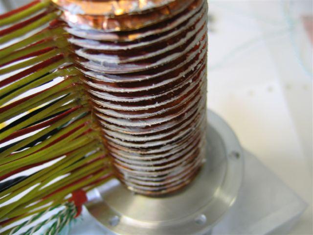
The inner diameter of the cooling jacket is slightly smaller than the outer diameter of the copper shims. When the jacket is slid over the coil stack this has the effect of bending the copper shims over, thus ensuring a good thermal contact between them and the jacket. A photograph of the jacket placed over the coil stack is shown in figure 5. The cooling pipe has a narrow bore and so the water flow rate is quite low. Typically, at 4 bar, a flow rate of 1 litre min-1 is achieved. This flow rate has proved to be sufficient to remove the heat from the coil stack during normal operation. A nominal stator operating temperature of 80 has been maintained, well within the working temperature range of all the components.
3.2.4 Stator Assembly
The coil stack is assembled over a former that has the same diameter as the insulated bore tube. The stack starts with a spacer followed by four copper shims. A coil, lightly coated on both sides with a thermal paste to aid with heat-sinking, is added. Six copper shims follow. The second coil is then added to the coil stack and the process is repeated for all twenty-four coils. As each coil has a nominal thickness of mm the cumulative error is tracked and minimised during the coil stack construction by selection of coils of appropriate thickness. An assembled coil stack is shown in figure 6.
The split in the copper shims aids in keeping the coils parallel during construction. This is achieved by placing the split in the shim where the wires to the coil exit. (There is sometimes a small bump at this point on the coil due to the wire exiting from the centre of the coil back over the top of the other windings). The gap created by the split in the shims also allows thermocouples to be inserted into the coil stack.
At this stage a cooling jacket is slid over the coil stack. The stator body is then completed by adding a split outer jacket and two end-caps. The split in the outer jacket allows the wires and the cooling pipes to protrude for external connection. The end caps provide light compression on the coil stack, keeping it in place. The former on which the coil stack was formed is now removed and the bore tube inserted through the bore of the stator. A final electrical insulation check is then performed, to ensure that all coils remain isolated from metal parts including the bore tube and cooling jacket. The installation of the stator body into the core of the target drive assembly is described in section 4.
3.3 Permanent magnets
The permanent magnet assembly interacts with the field of the stator coils to produce the force on a central shaft which accelerates the target into and out of the proton beam. To achieve the maximum magnetic field, the assembly is constructed from sintered neodymium-iron-boron (NdFeB) magnets. Twenty-four segments are arranged in 3 rings, with 8 magnets per ring, as shown in figure 7. They are glued to a mild steel core to produce a cylinder that is 18 mm long with an outer diameter of 15 mm and an internal diameter of 4 mm. Thin ceramic washers separate the three rings. The central ring is 7.8 mm long, twice the length of the two outer rings. The whole assembly has a mass of about 25 g.
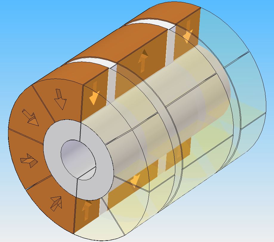
The individual sectors are manufactured by wire erosion from un-magnetised NdFeB material. The sectors are then magnetised radially and assembled in a jig before finally being glued in position using a strong two-component epoxy. Once the glue is cured, the magnet unit is lightly machined to the precise outer radius required. The middle ring is magnetised so that the outer surface is a North pole, while the outer rings have the opposite polarity.
A FLUKA [13] simulation has been performed to ascertain the radiation levels expected around the target. Assuming 24 hour operation at 1 Hz for 180 days in a nominal year, the expected radiation dose to the magnets is estimated to be Gy. To date, no evidence of degradation due to radiation has been observed.
4 Mechanical design and construction
The MICE target unit contains mechanical components and sub-assemblies that are designed to:
-
•
Combine accurately all mechanical, electronic, electrical-power and optical-readout functions into a single unit;
-
•
Provide a vacuum tight volume connected hermetically to the ISIS beam-line;
-
•
Enable target operation by:
-
–
Providing controlled drive of the target’s shaft into and out of the beam;
-
–
Enabling the velocity and location of the shaft to be determined;
-
–
Constraining the shaft along its path of travel thus preventing significant off-axis movement;
-
–
Providing stiffness in the shaft that resists significant deformation and vibration during operation.
-
–
-
•
Eliminate the possibility of a failure that prevents continued operation of ISIS beam, including:
-
–
Breaking of the shaft such that part falls into the circulating beam;
-
–
Failure of welds or seals causing a leak into the ISIS vacuum chamber; and
-
–
Contamination of the ISIS vacuum chamber, particularly with metallic or other dust that could contaminate the RF cavities.
-
–
-
•
Deliver an operational lifetime that is sufficient to allow a rolling programme of maintenance at appropriately infrequent intervals.
4.1 Target shaft
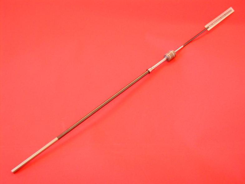
The shaft comprises of two sections of titanium (Ti) alloy grade 5 (6% Al, 4% V). The sections are a solid upper section and a lower tubular section with various functional features on each. The two halves are joined with a shrink-fitted plug-and-socket arrangement then electron-beam welded together. The shaft is coated with a hard diamond-like carbon (DLC) coating that acts as a bearing surface. The shaft is finally fitted with a permanent magnet, a slotted graticule for position read-out and the associated fixings and fasteners.
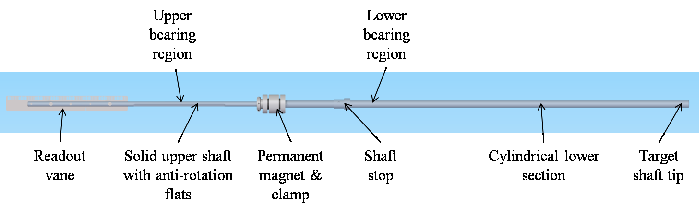
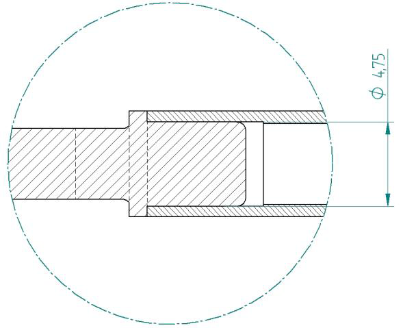
The shaft is 528 mm long and, when fully assembled with the magnet, slotted graticule and fixings, has a weight of g. A radially segmented, permanent-magnet assembly is bonded to the shaft and held with a mechanical clamp of minimal mass (1.5 g). The stator accelerates and then decelerates the shaft in both the down-stroke and the up-stroke with a maximum travel in each direction of around 48 mm. The shaft achieves this 96 mm of reciprocating movement in about 30 ms before dwelling and then dipping again; with the dwell the shaft dips at a frequency of just under 1 Hz. The tip of the shaft has a cylindrical cross section of 11.5 mm2 (5.95 mm outside diameter and 4.55 mm inside diameter); as it is an integral part of the tubular lower shaft it is grade 5 titanium alloy. It is the tip of the hollow cylinder that momentarily grazes the halo of the ISIS beam to produce pions.
The production quality of the target shaft is the most critical aspect of all the manufacturing process. The shaft is manufactured within very tight dimensional and geometric form tolerances. The tight dimensional tolerances ensure the close fit of the shaft with the bearings; this tight fit accurately constrains the shaft’s vertical motion. The shaft requires a high degree of straightness and good roundness. Tight tolerances of form (cylindricity and run-out) are applied to the manufacture of the shaft; accurate form minimises deformation and vibration of the shaft during the rapid acceleration and deceleration.
4.1.1 Design
Though form is accurately controlled, it is not perfect. Add to this a non-perfect constraint in the bearings and a stiffness limited by mass, geometry and material properties, then the rapid acceleration and deceleration of the shaft will cause it to deform and vibrate during operation. The stiffness of the shaft is very important. Increasing the stiffness of the shaft, without increasing mass, pushes up the frequencies of resonant modes. Increasing the frequencies, especially those of the first few resonant modes, reduces the number of resonant modes the shaft passes through as it is accelerated and decelerated. Excitation of vibrations in the shaft may arise from a number of sources, including:
-
•
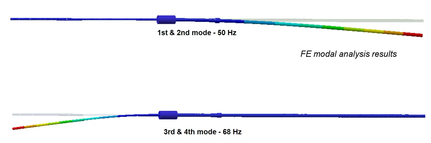
Large changes in velocity take place at ms intervals, i.e. twice over the 30 ms cycle. If the natural frequency of the shaft is close to 33 Hz or 67 Hz some distortion will be induced.
-
•
The switching of power from one set of coils to the next may introduce an excitation force. The longitudinal driving force (up to 50 N) may be accompanied by off-axis torque or lateral forces as the sequential coil-switching takes place during dipping. The frequency and severity of the excitation would be directly linked to the timing and magnitude of these forces. The timing of the switching is variable as the shaft is accelerated and decelerated in both directions, so the frequency of excitation is variable too. This may cause the shaft to pass through several excitation frequencies that correspond to the shaft’s resonant frequencies. The magnitude of the excitation depends on the force seen by the shaft when switching between coils; this is related to the quality of the coils and their axial location relative to the permanent magnet. With a 0.5 mm offset in coaxiality between the permanent magnet and the coil’s magnetic centre the lateral forces have been calculated to be up to 2.5 N and the torque up to 32.5 mN m.
-
•
The unit or surrounding support frames may be excited by the dipping shaft. There is potential for this vibration to transfer back from the support frame to the shaft through the stator and the bearings. There is significant vibration felt on the test frame after each dip.
A tubular, ‘O’ section shaft was shown to have sufficient stiffness. A finite-element (FE) modal analysis showed the 1st and 2nd resonant modes at 50 Hz, but the 3rd and 4th at 68 Hz.
The tubular lower section is created by rough-machining a bar to leave a slightly oversized external profile, including an integrated mechanical end-stop. This is then heat-treated to remove residual stresses. The bore is then wire eroded to 4.55 mm ID over the length of the lower shaft (about 320 mm); if internal stresses were present the shaft might deform along its length as this material is removed. After wire erosion the external profile, including the stop, is finished to final size referenced to the bore to maintain concentricity and thus material balance. Finally the socket for the shrink-fit joint is added.
The upper shaft stock material is stress-relief heat-treated before manufacture. It is then ground; this includes the flats which are very finely ground to ensure internal stresses are minimised. A larger diameter is left at one end onto which the socket for the shrink-fit joint is machined. Also added are the undercut for the magnet clamp and the fixing holes for the laser readout graticule. The very fine slot for the graticule is then cut by wire erosion. The wire erosion of this slot causes the two adjacent sections to open in a ‘Y’ shape. (This is only seen on the grade 5 titanium shafts and not on the previous versions made from commercially pure Ti grade 2; in fact the slot collapsed slightly when using Ti grade 2.) It appears the wire cutting causes a slight expansion in the surface material on the inside of the slot that forces these sections to fan out. This has been resolved by supporting the shaft with the slot closed and stress-relieving back to a correct form.
To alleviate the risk of undertaking so many operations on a long single-piece shaft it is produced in two sections. The additional benefit of this is that they can be produced concurrently with benefits to the schedule. The lower shaft has an accurately machined socket and the upper shaft has a mating plug. The plug and socket are manufactured with a nominal 0.01 mm interference press fit. If these were pressed together at ambient temperature the material would cold-weld. Cold-welding is unlikely to be uniform and so the joint would skew causing a significant form error between the upper and lower shaft sections; it may even seize before it is fully pressed together. To achieve a clearance as they are assembled (i.e. to prevent cold welding or galling) the socket is expanded by heating to 250 and the plug is shrunk by cooling to in nitrogen. A precision jig is then used to ensure correct alignment as the pieces are pushed together. The interference-fit is made as the joint comes back to room temperature, contracting the socket and expanding the plug.
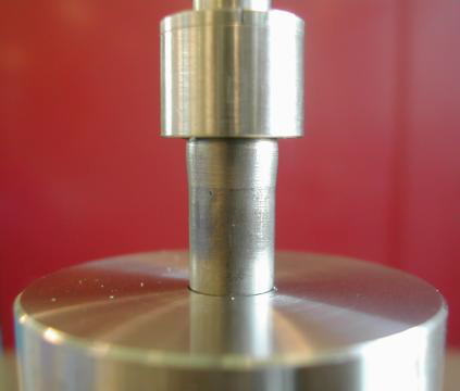
The two halves are further secured by welding at 8 points along the seam between the plug and socket using electron-beam (EB) welding. A full circumferential weld was originally tried, however under-run or over-run at the end of the weld always made the two halves skew too much. Tensile testing was used to determine the strength of the shrink-fit and point-welded joint. Tensile testing broke the spot-welds at 4 kN which coincided with an audible crack as the welds broke. After the welds broke the interference-fit of the plug and socket prevented the shaft breaking into two halves; instead the tensile load began to climb in finite steps against displacement to 6 kN before the test was stopped. This was due to a cold-welding effect; this is beneficial as it significantly reduces the chances of the shaft breaking into two should high impact load occur during a fault.
4.1.2 Material
Titanium is a good target material with respect to particle production, it is widely available, it can be easily worked and can be joined by welding. The shaft needed to be low mass to enable rapid and efficient acceleration by the stator. The shaft also needed to be stiff to minimise elastic deformation and vibration during its operation; titanium and its alloys have a good stiffness-to-mass ratio.
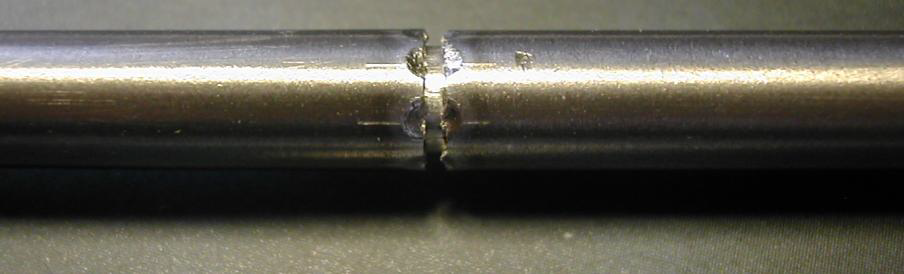
The initial redesign of the lower shaft led to the use of a tube with a mechanical stop welded on; tube in unalloyed grade 2 is widely available and was initially chosen for the shaft material. Impact testing was undertaken on this welded-stop design; this closely represented a shaft’s mechanical end stop impacting the lower bearing at a maximum speed of 9.3 m s-1 during a fault condition, including a safety factor of 1.5. A mass was dropped from a set height onto the stop on the lower shaft. This stop failed at around 4 impacts. In addition a bulge started to form in the wall of the tube due to the impact, see figure 13. Though the EB welding is a semi-automated process there is potential for variability in the strength of the weld, so the welded-on stop was not an entirely risk-free choice. In addition the welding of the stop caused some distortion to the tube that had to be corrected by mechanical manipulation. It was decided to pursue a more costly manufacturing route to produce a stop integrated into the lower section from a single bar, a much stronger design. This overcame the restriction of obtaining only grade 2 tube and allowed consideration of titanium alloys.
Grade 5 (Ti-6AL-4V) titanium alloy was eventually chosen. There is a slight improvement in stiffness with the grade 5 titanium alloy over the unalloyed grade 2 titanium, 114 GPa and 103 GPa respectively. The additional strength of the grade 5, 895 MPa minimum over the 395 MPa minimum of grade 2, is of no significant benefit as the loads on the shaft are minimal during normal operation and the integrated-stop design is much stronger. The biggest benefit of grade 5 over grade 2 is in the hardness – Rockwell C 36 and 21 respectively in an annealed state. The harder alloyed grade 5 is easier to grind, allowing better finishes and tighter tolerances to be achieved. This is particularly useful for the upper shaft where the diameters and flats are ground.
4.1.3 Manufacture
Grinding is used to produce the main geometry of the upper shaft. The depth of cut in the grinding process is reduced towards the final cut to minimise the amount of deformation induced into the surface of the component; this in turn minimises internal stresses in the final shaft. Internal stresses may relax via strain over time leading to warping of the shaft. Grinding also gives the shaft a fine surface finish so that polishing removes only a minimal amount of material in achieving the final surface roughness of 0.05 Ra.
Stress-relief annealing is undertaken on raw materials before processing as well as at certain stages throughout the processing. This removes internal stresses induced by manufacturing processes. Unrestrained heat treatment to around 670 with a dwell period of minutes followed by a slow cool relaxes the stresses through strain, which deforms the material slightly. This deformation is removed during subsequent processing to achieve the final component’s size with minimum internal stresses. The temperature and heat treatment cycle information was taken from [14].
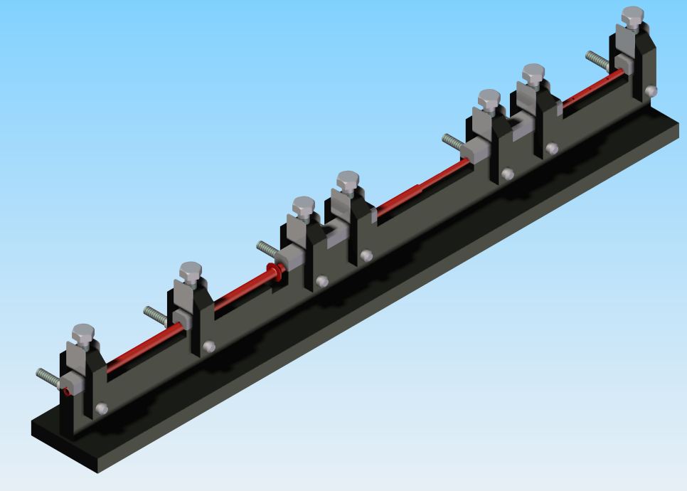
A stress-relief anneal is also applied to the assembled shaft prior to the final DLC coating process to straighten it. The shaft is held firmly and accurately in a jig, see figure 14. The jig is made from mild steel which is itself stress relieved (at 700 ) before an accurate ‘V’ is finely ground into it that supports the shaft. Mild steel has a similar coefficient of expansion to titanium alloy, 11 ppm/ and 9 ppm/ respectively; this means during expansion and contraction upon heating and cooling there will be minimal force induced by the jig on the shaft. Mild steel is also a dissimilar material to the titanium alloy so there is less chance of the jig and the shaft bonding at the elevated temperatures during heat treatment. The latest shafts have all undergone this process and have been straightened from >0.5 mm run-out post manufacture to around 0.1 mm run-out post treatment.
Conventional machining, such as milling and turning, is used on many features including the profile of the lower shaft, the fixing holes for the graticule and the plug-and-socket features used to join the upper and lower shaft sections.
Wire-erosion is used to create a 90 mm by 0.22 mm slot in the upper shaft to support the graticule. The 4.55 mm inner diameter, 320 mm long bore through the lower shaft is also made by wire-erosion.
The sub-components of the shaft, and the fully-assembled shaft, are inspected at many stages during manufacture to determine if they meet the specification on the technical drawings. Further information on the inspection of the shaft is given below.
Diamond-like carbon (DLC) coating is applied to the bearing surfaces of the target shaft. These surfaces are polished prior to DLC coating to ensure the final finish is smooth. The tip of the shaft that dips into the beam is not coated. The tip is left uncoated to prevent any thermal heating, from contact with the ISIS beam, causing failure of the coating through high temperature (>400 ) or through thermal strain differentials.
4.1.4 Shaft measurement
The shaft cannot be made perfectly straight due to its long thin shape, but as long as the form is controlled within tolerable limits operation will be acceptable. During manufacture care is taken to produce the shaft sections with the best possible straightness, minimising run-out between the bearing regions as well as finely balancing material about the axis of the shaft. Manufacturing includes the use of jigs to hold the shape during processing, heat-treatment stages to relieve stresses and a final constrained heat-treatment to achieve the desired shape. Shafts are accepted with a run-out between bearing regions of less than 0.12 mm; through prototyping it was proved that shafts with such run-out operated acceptably in the target unit.
The size of the shaft is very easy to measure using conventional micrometers. The shape however is more difficult. For the shaft a Taylor Hobson Talleyrond is used to measure the run-out between the lower bearing region and the other parts of the shaft. The Talleyrond has a rotating table onto which annular parts are clamped; a probe on an extending arm then measures the exterior of the annular component as the table rotates. A jig was produced for shaft measurement that allows the Talleyrond to access relevant sections of the shaft for measurement. It uses an upright post to support a collet assembly; by lightly press-fitting the shaft into the collets, then the collets into a holder, the shaft is secured and aligned. The larger diameter lower bearing region is chosen to be the datum from which all other surfaces are measured. The Talleyrond is programmed to locate this surface by measuring the circumference over a number of positions along its axis. It then aligns the lower bearing region with the axis of rotation, by automatically adjusting the plane of the table. Next it measures the other sections of the shaft. Again the Talleyrond measures the circumference over a number of places along the axis of the region to produce a profile of slices. These 2-D slices can be stacked to produce an extrapolated 3-D model of the shaft as well as being referenced to the lower bearing datum. The probe has an extremely light touch (1.5 mN), but this is enough to bend the shaft elastically when measuring further away from the collet supports. A fine sprung-arm counter-balance is placed to oppose the probe arm to counteract any forces from the probe during measurements.
4.2 Target bearings
4.2.1 Description
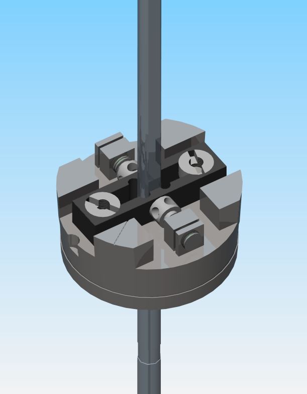
Plain bearings support and constrain bearing regions on the shaft. There are two bearings, one to restrain the upper section of shaft and one to restrain the lower section. They are required to constrain the lateral motion of the shaft as it dips, as well as incorporating an anti-rotation feature to prevent significant rotation about the longitudinal axis of the shaft. The upper bearing has the anti-rotation component; it is finely adjustable via screws to ensure accurate location with respect to the anti-rotation flats on the upper shaft. The bearings have plastic (Vespel® SCP5000) inserts and anti-rotation components (the dark items in figure 16). The plastic parts are assembled into stainless steel (Nitronic® 60) carriers. Nitronic® was chosen as it minimises cold welding when the fine location taper on the outside of the bearing carriers are lightly pressed into the tapered bearing seat in the 1.4404 / 316L stainless steel body.
4.2.2 Material
For the bearings the material and coating combinations at the bearing interface with the shaft were very important for function and longevity. A number of material and coating combinations have been tried for use on the target. From the early trials of different coatings, a diamond-like carbon (DLC) coating on both the shaft and the bearing was found to be suitable. Despite these early successes, there subsequently appeared to be too much variability in the quality of this coating. This may have been due to the geometry of the parts being coated; the small bearing hole, even if produced in several segments, produced a “hollow cathode effect” in the RF coating chamber, thus variability in the thickness and adhesion of the DLC coating. This variability led to coatings on some shafts and bearings wearing away rapidly in later trials.
The alternative to DLC came from cryocooler technology as designed and built by STFC’s Cryogenics and Magnetics Group. The cryocoolers have demonstrated in excess of 1010 cycles in a dry helium atmosphere. The material combination used in these cryocoolers is titanium (both commercially pure and 6% Al, 4% V) against Vespel® SP-3 grade. The SP-3 grade of Vespel® is a polyimide that contains molybdenum-disulphide (MoS2). MoS2 is a dry lubricant which lowers the coefficient of friction. However MoS2 was rejected on the grounds that long-lived isotopes might be produced in the high radiation environment. DuPontTM Technical were contacted to determine if an unfilled alternative may be suitable. From the following requirements it was determined that Vespel® SCP5000 would meet the needs of the target when operating on the ISIS beam-line.
Bearing surfaces have a higher coefficient of friction in the ISIS vacuum of 10-7 mbar [15], i.e. without the presence of moisture or lubricating films. A high coefficient of friction between bearing surfaces will increase the power required to drive the shaft, it will cause accelerated wear of the bearing surfaces and it will raise the temperature at the bearing interface through frictional heating. SCP-5000 was recommended for use as it has a relatively low coefficient of friction, even in a vacuum environment, of 0.26 or better [16].
Bearing materials are required to be tolerant to the effects of the nuclear radiation generated in ISIS, i.e. their mechanical properties must not change significantly during the operational life of the unit. Vespel® is a polyimide which will tolerate a significant total accumulated ionising radiation dose before a loss in mechanical properties.
Particles created during wear should be kept to a minimum. If they are created they must be managed and contained within the unit. This is particularly important for particles that have become activated, for health and safety reasons. In addition particles should not be released from the unit as they may damage the RF cavities adjacent to the MICE target in ISIS. Dust is produced when using the Vespel® bearings, however with a finely polished shaft this has been minimised. The target unit has been fitted with an extended housing with dust-traps to prevent the dust produced from the Vespel® escaping outside of the unit, see figure 17. The bearing surfaces need to withstand a significant operational life and be able to be manufactured with fine surface finishes and tight tolerances to minimise the rate of wear; Vespel® is a relatively hard plastic so suits this.
The material must not significantly out-gas in the ISIS vacuum. Out-gassing tests were undertaken on vacuum-baked samples of Vespel® SCP5000 (80 for 72 hours) which were shown to be acceptable for use on the ISIS beam-line provided the total volume was kept below 3 cm3.
4.2.3 Rotational constraint
The position of the shaft is determined using an optical vane (section 5.1) which must be held roughly perpendicular to laser beams. The orientation of the shaft must thus be restricted to a range of about . The range is limited to less than by providing the upper section of the shaft with a pair of finely-polished parallel flats that run against a flat-faced Vespel® anti-rotation component on the bearing, see figure 18. The flat faces of the anti-rotation component are finely adjusted so that the flats on the upper shaft only contact them if the shaft rotates. In trials using an anti-rotation component with two completely flat faces, it was found that after running for some time the corners of the flats on the upper shaft would dig-in to the plastic and cause the shaft to lock temporarily; the semicircular reliefs shown in figure 18 were added to prevent this.
4.3 Stator
4.3.1 Description
The stator assembly surrounds the middle portion of the shaft assembly, including the permanent magnets which are driven by the coil stack. The bearings and stator assembly are fixed in the core structure (see below) to coaxially align the shaft assembly and permanent magnet with the coils.
The stator, described in section 3.2, is a self-contained sub-assembly; it is assembled around, but not fixed to, the central vacuum tube. As it is self-contained it can be tested independently. After assembly and test the stator unit is incorporated into the target unit by welding the ends of the vacuum tube into the two main core body components. The tube and welds provide an uninterrupted vacuum volume though the middle of the unit. Above and below this central vacuum tube, the components are fixed to the body with copper knife-edge (CF) seals. When the stator drives the shaft there is a reactive force of up to 50 N. As the stator is not fixed to the vacuum-tube this load is not transferred to the vacuum-tube welds. To prevent the coils within the stator moving, or the stator moving as a whole, the stator unit is clamped down inside the core body using three stacks of disc springs. These springs exert a clamping force of around 100 N onto the stator unit when the upper flange of the core body is fully tightened onto the core tube.
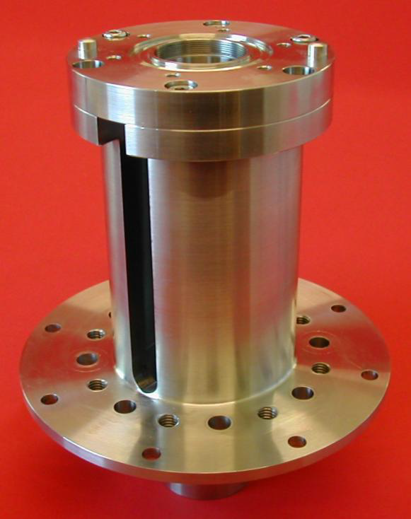
4.4 Core structure
The core structure of the target is provided by two robust stainless steel (1.4404 / 316L) components, the core tube body and the upper flange. These contain the stator unit and the bearings. The other components of the target assembly, such as the electrical wiring and the covers, are also fastened to these core components.
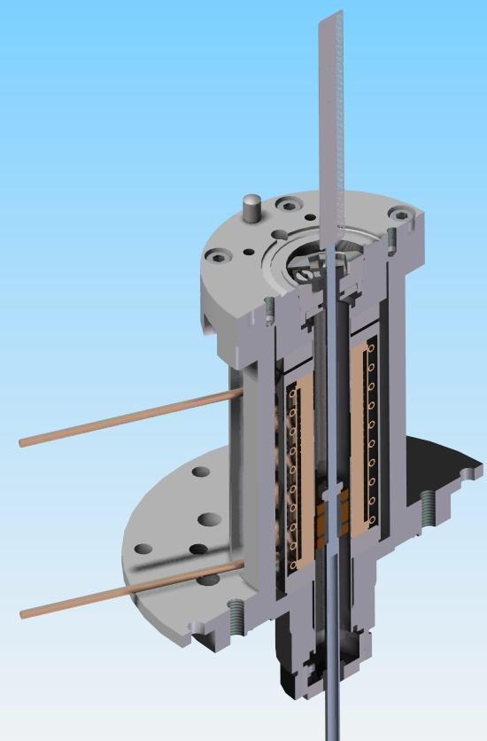
The core is required to align the other components accurately and stably, in particular to provide the accurate coaxial alignment of the permanent magnets on the shaft and the stator coils. Careful consideration of the interfaces between the permanent magnet and the stator coils was required. The order of the interfaces relating to this critical alignment of the permanent magnet and stator coils are represented by ‘’, and are shown below:
Permanent magnet Shaft Bearings Core structure Vacuum tube Stator coils.
This number of interfaces requires each component to be manufactured to tight tolerances, then accurately assembled with respect to each other. Coaxial alignment between the permanent magnets and the magnetic field of the stator reduces or eliminates off-axis torque or lateral forces on the magnets as they pass through the stator’s changing magnetic field.
Accurate alignment of the bearings is also very important. The bearing alignment, bearing-bore accuracy, straightness of the shaft and tolerances on the outer diameter of the shaft all build up to increase the minimum radial clearance tolerable between the bearings and the shaft. Keeping this radial clearance to a minimum ensures the shaft’s travel is well constrained. If the radial clearances have no added compensation for manufacturing variations, the fit could be too tight which may lead to flexing of the shaft and possible fatigue failure or high power loading on the stator. To achieve accurate bearing alignment the core structure and the way it supports and locates the stator assembly has been simplified to the minimum number of components and interfaces. There are only two components and three interfaces between the 2 bearings:
Bearing Core lower Core upper Bearing.
Minimising the components and the interfaces is a practical solution for machining as there are few tight tolerances to be achieved. To further aid the accuracy of alignment of the bearings and reduce the manufacturer’s liability in achieving tight tolerances, the two core parts are made with a slight clearance fit; they are then assembled, inspected, adjusted to achieve a tight coaxial alignment, then dowelled together. The Taylor Hobson Talyrond is used to undertake the inspection of the alignment of the core body components. The bearing seats are aligned to each other within 20 m of run-out; the repeatability of reassembly alignment with the taper dowels is around 10 m.
The bobbin that supports the stator has a central bore where the permanent magnet runs up and down. The bobbin is welded into the core assembly so that it forms a hermetic seal from the flange on the upper flange to the flange on the core tube body. These flanges incorporate CF-type seal features which use knife edges to compress copper seals. A hermetically sealed internal vacuum volume is created when the optical housing and bellows are fitted to the core assembly and the bellows are then fitted to the vessel in the ISIS ring or the test vessel.
The core tube body has a small flange which is fitted with a larger flange extension. This extension is the main reference component for positioning the assembly on ISIS. Rods are suspended from a frame, either above the beam-line or on a test vessel in a separate building (for offline running and trials), as described in the next section. These rods fix to the larger flange extension and support the target unit for connection to the beam-line or vessel. The two-part flange is a practical solution for manufacturing as it minimises the material cut away from stock billets to form the components.
4.5 Mechanical integration
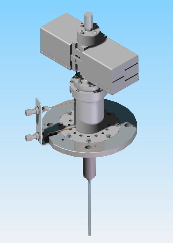
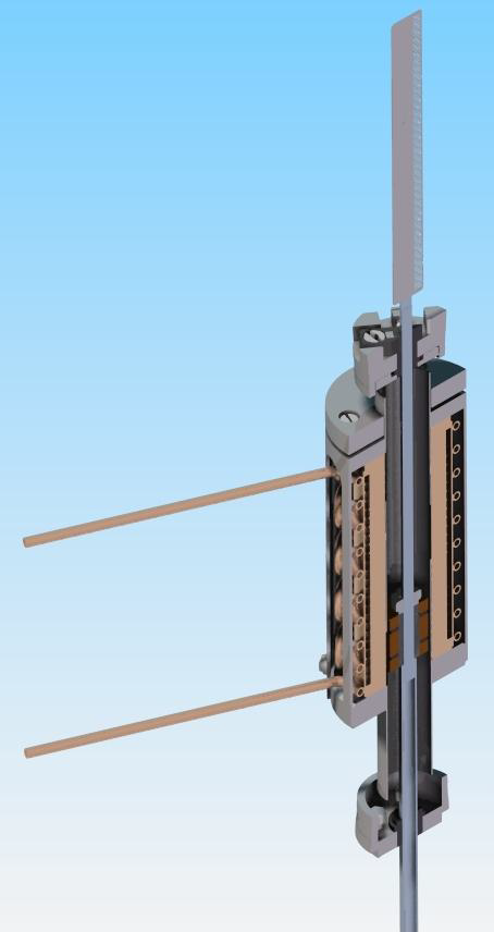
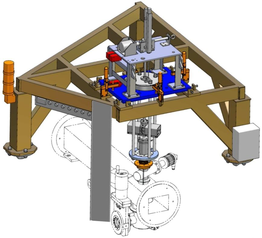
The target mechanism must be rigidly supported in a manner which minimises the transfer of vibrations caused by the linear motor to the synchrotron itself. The target must also be removed from ISIS when it is not in use and complete isolation must be possible in the case of a fault developing in the mechanism. These objectives are met by suspending the target from a heavy, rigid steel frame which is itself bolted to pillars resting on the synchrotron floor, see figure 21. A motorised platform raises and lowers the target drive, which is connected to the beam-pipe via a set of extensible bellows and a remotely operable valve which can separate the vacuum systems of the synchrotron and the target drive. A duplicate section of beam-pipe, complete with target support frame, is situated in an assembly hall where all target mechanisms were commissioned.
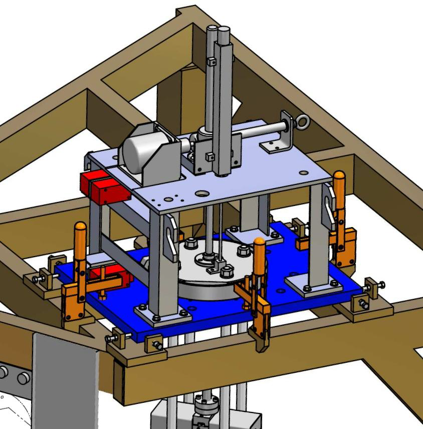
4.5.1 Motorised platform
A heavy steel plate rests on the main support frame. This carries a motorised screw-jack driven by a stepper motor (see figure 22). The jack can raise and lower a steel ring, which carries the main target mechanism via three sturdy rods passing through holes in the plate. The jack has a travel of 207 mm and, when in its lowest position, the ring fits into a locating socket. The motor is controlled remotely, and limit-switches indicate when the mechanism is at its highest and lowest positions. The switches are interlocked to the control system to prevent the equipment from being driven outside safe limits. An independent position switch is linked to the Personnel Protection System, and prevents the target mechanism being lowered while access is allowed to the MICE Hall and ISIS is operating.
The plate is supported on levelling screws, and its lateral position is adjusted with locking screws to ensure the target is centred over the port in the beam-pipe. Once positioned, the plate is clamped in place.
During normal target operation, the support frame is moved to its lowest position. The tip of the shaft is then outside the beam envelope only while it is magnetically levitated. When the target is not in use, the frame is raised to its highest position and the target is well clear of the beam even if powered down.
4.5.2 Bellows and ISIS vessel interface
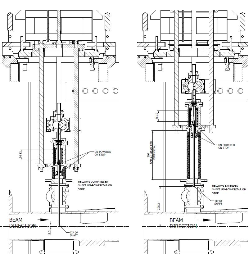
To allow vertical movement of the target drive while maintaining a vacuum seal, the lower flange of the drive is connected to the beam-pipe using edge-welded bellows (see figure 23). These have an internal diameter of 46 mm, a compressed length of 56 mm between flanges and an extended length of 260 mm. The UHV seal between the bellows and target flange is maintained with a standard Conflat seal and copper gaskets.
As a fault in the target mechanism could compromise the ISIS vacuum, it is important that the target vacuum space can be isolated from the accelerator. This is achieved with a gate valve, mounted between the flange on the upper face of the vacuum vessel and that at the lower end of the bellows. Seals are formed using aluminium gaskets compressed by V-band clamps. The valve is operated by a low-pressure nitrogen line, controlled remotely, and has an aperture of 40 mm to allow the passage of the shaft. The control system ensures that the frame cannot be lowered while the valve is closed and that the valve cannot be closed unless the frame is at its upper limit-switch.
The ISIS vessel is adapted for the presence of the MICE target in several ways. As well as the port on the upper surface to accept the target mechanism via the gate valve and bellows, it has a thin-walled steel window to allow the passage of pions, produced by interactions in the target, into the MICE beam-line. In addition, it has a glass inspection window directly below the target. This allows visual observation of the shaft tip.
4.6 Magnetic inspection
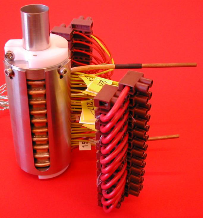
To characterise the magnetic performance of the target mechanism, magnetic measurements are carried out on the stator and on the permanent magnet assembly. The equipment used is a three-axis Hall probe mounted on the end of a travelling arm. The position of the probe can be set to a resolution of 1 m in three axes.
4.6.1 Stator
For the stator, measurements are required to define the position of the magnetic centre of the coils relative to the mechanical centre. If the coils are offset, the small radial field they generate may have the effect of moving the shaft laterally as it passes through the stator. Accurate alignment of the magnetic centre is therefore important to minimise wear on the bearings during operation.
The coils are powered using a constant current of 7 A; this is lower than the peak current when the shaft is dipped into the beam due to heating concerns – a constant current of 60 A would overheat the coils. The current of 7 A heats the stator to around 50 when water cooling is used.
The stator is set up and aligned to the measurement bench. A cross-hair on the end of the Hall probe is viewed through a telescope as the probe is moved up and down the bench; this allows the telescope axis to be set parallel to the bench axis. Cylindrical inserts with a precisely machined central hole are placed in either end of the stator bore in turn, to allow the stator axis to be aligned parallel to the bench axis. The estimated accuracy of this procedure is around 100 m at each end, which gives an overall alignment accuracy of 0.8 mrad over the 180 mm length of the stator.
An initial scan of the stator along the longitudinal () axis shows a series of peaks corresponding to the individual coils. To find the centre of each coil, a two-dimensional scan at each peak position is carried out (Figure 24). The magnetic centre is the point at which the longitudinal field is a minimum. The longitudinal field is fitted to the function:
The centre point can then be found from the fit to the data, using the formulae:
4.6.2 Permanent magnets
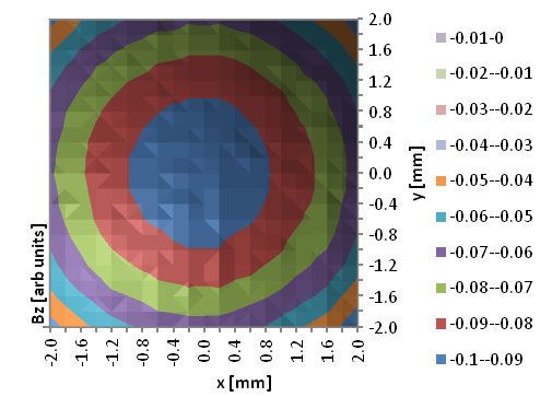
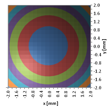
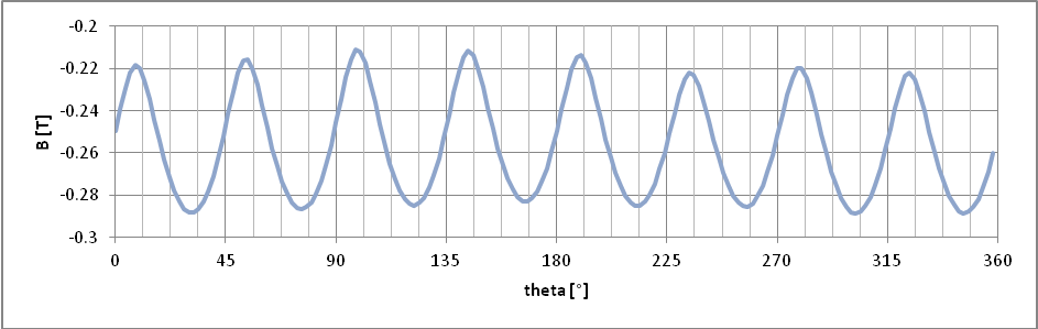
For the permanent magnets, measurements are carried out to determine azimuthal variability of the radial field (i.e. vs ). Due to variations in the PM blocks, there is a certain amount of variation in the peak (and trough) values of the radial field. An assembly with smaller differences between the peaks would be preferable, as it may reduce lateral movement and vibration of the target shaft during operation.
The PM assembly is attached to a rotational stage in order to map the radial field as a function of angle and longitudinal position. In this case, the Hall probe is attached to a spring-loaded head to keep it the same distance from the PMs (about 1 mm) as the assembly is rotated. This was found to be necessary since the PM assembly was not parallel to the Hall probe axis. The effect is small – a few tens of microns as the PM assembly is rotated – but enough to give a significant difference in the measured field, as the field drops off rapidly with radius. Figure 25 shows a plot of the radial field versus angle.
5 Optical position-measurement system
In order to switch the current through the coil stack at the correct time to drive the shaft, it is necessary to sense the position of the shaft while it is moving. To avoid disrupting the motion of the low-mass shaft by mechanical contact, and to remove the necessity for electrical feed-throughs traversing the vacuum wall, an optical method is adopted. Furthermore, since active electrical components would not survive in the high radiation environment near the target, optical fibres are used to convey the signals, with all sensitive electronics being placed outside the accelerator vault (in the experiment control room some 100 metres away).
A graticule, or vane, attached to the shaft and interrupting a light beam will generate a series of pulses, which could be used to determine the speed but not the direction of movement of the shaft. If it is arranged such that two beams are interrupted by the vane, with the pulse trains being out of phase, then both speed and direction can be determined. (This is known as a quadrature system.) With a third beam producing a pulse at only one well-defined point, a zero of position can be defined. In this way, by counting pulses away from the zero, an absolute position measurement can be made.
In addition to providing feedback to the controller, position measurement allows the trajectory of the target to be monitored and recorded by the data acquisition system. This enables the long-term monitoring of the stability of the mechanism and the diagnosis of fault conditions.
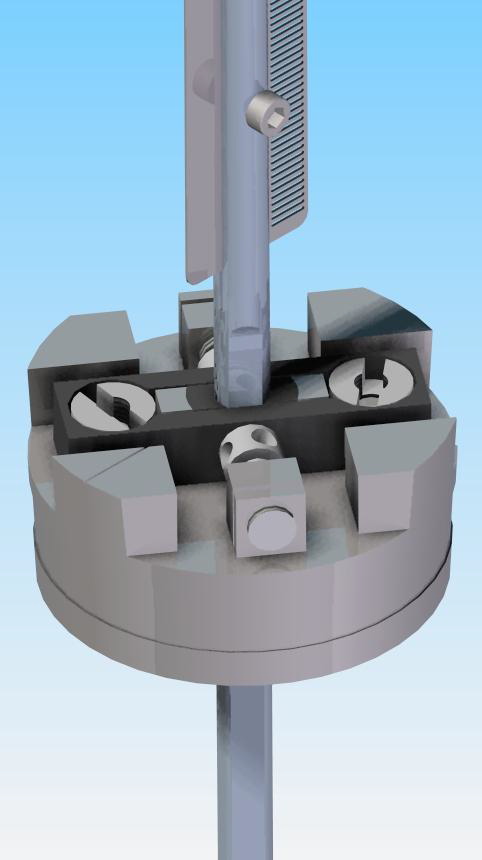
5.1 Optical vane
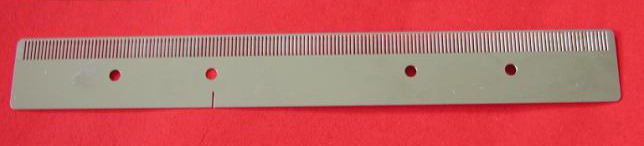
A photograph of the vane is shown in figure 26. The vane is a double-sided graticule manufactured from 0.2 mm thick steel, having 157 slots 0.3 mm wide and 3 mm long on one side of a 6 mm wide spine. The whole vane is 93.9 mm long. The spacing between slots is also 0.3 mm. There is a single similar aperture two-thirds of the way down the vane on the other side. To protect the fine features of the vane, it has a continuous edge. The vane was produced by photographic etching, and is attached to the shaft by four M1.6 screws. In order to ensure that the readout system provides reliable position information, the manufacturing tolerances of the apertures were kept to less than 5% of the 150 m resolution, and the tracking error along the length of the vane was also less than this percentage. The vane and fixings have a mass of about 1 g, which is balanced about the axis of the shaft.
5.2 Laser source
Three fibre-coupled solid-state lasers provide the light beams which intercept the vane. Commercial red (635 nm) lasers, with a variable 0 to 2.5 mW output power are used. Visible light has advantages both for alignment and safety. The milli-Watt power level is required due to significant losses in the optical system owing to the number of optical interfaces. Maximising the light on the optical sensors (Section 5.5) increases the signal to noise ratio and simplifies the design of the electronic amplifiers.
In practice, the lasers are not operated at maximum power, but at about 1 mW. This leaves sufficient overhead (both in light source and amplification gain) to adjust for any degradation in the optical fibres, e.g. increased attenuation as a result of radiation damage.
5.3 Optical fibres
Two types of optical fibre are used. On the transmitting side, single mode fibres are required to achieve the necessary small spot size at the focal point and hence at the plane of the vane. On the receiving side, 200 m multimode fibres are used.
The single mode fibres used are SM600 with FC-to-FC connectors [17]. These fibres have a core of pure silica, which is a radiation-hard material and so ideal for the operating environment of the target. If single-mode fibres were used on the receiving side, the collimators would have to be aligned to an extremely high precision and it would be hard to achieve an adequate light transmission. Multimode fibres have a higher acceptance, so make the alignment less critical. The fibres used are BFH37/200 purchased from Thorlabs, with SMA to SMA connectors [18].
5.4 Collimators, lenses and mechanical mount
Collimators and lenses are used to focus the light from the fibres to a spot in the plane of the optical vane (where it needs to be significantly smaller than the pitch of the vane) and to receive the transmitted light coupling it into the return fibre. The collimator is a commercial unit which produces parallel light from the diverging beam emitted by the fibre. Collimators with a focal length of 15.3 mm are used, as the longer focal length minimises the final spot size. The focusing lens, with focal length 45 mm, is attached to the front of the collimators by inserting it into a holder which is screwed onto the front of the collimator as shown in figure 27. On the transmitting side, aspheric double achromatic lenses are used to obtain the minimum spot size. On the collecting side, where focusing is less critical, double convex lenses are used to re-collimate the beam. The lenses are MgF2 coated to minimise reflections and maximise the light transmitted into the fibres.
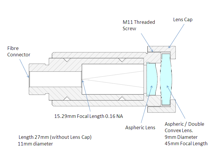
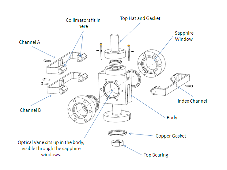
The optical vane moves inside the accelerator vacuum system, while all optical elements are kept outside the vacuum chamber to allow alignment adjustments. A mechanical mount was produced which has two circular sapphire windows, to allow entry and exit of the light and to provide a rigid assembly to support the optical collimator and lens units. This is illustrated in figure 28. The flat windows are bonded into metal flanges and are rated for use in UHV environments. The pair of collimators for each optical channel is held in an arm that wraps around the mount. The exact alignment of each collimator is performed by adjusting pairs of opposed grub screws, with 4 pairs per collimator: horizontal and vertical at front and back of each collimator. The “Channel A” and “Index” arms are also adjustable in the vertical direction to allow the correct quadrature phase to be obtained and an appropriate index position to be set. The mount has proved to be easy to set up and extremely robust. Once aligned on the bench, no further optical adjustments have been necessary during periods of operation lasting several years.
5.5 Optical sensors
The multimode fibres are returned to an SMA photodiode (H3R880IR)[19]. This is a broad spectrum photodiode (400 to 1100 nm). As the maximum velocity of the target is less than 10 m s-1, the maximum data rate per channel is only 33 kHz, well within the response capability of these devices. The outputs from the photodiodes are amplified and conditioned before being converted into digital signals.
6 Stator operation and power electronics
6.1 Introduction
The target drive is a three-phase, brush-less, permanent-magnet DC linear motor. Before considering how the force on the magnetic assembly changes with respect to its position within a powered coil stack, it is necessary to understand how the coils in the stator are wired and how they are switched.
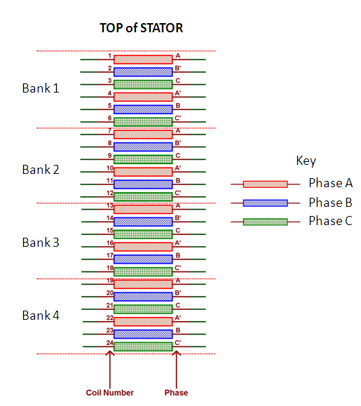
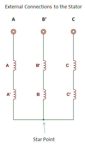
The 24 coils in the stator are split into three phases , and , with eight coils in each phase. Starting from the top of the coil stack (see figure 29), the coils are lettered in a cyclic sequence that follows the pattern, . A block of six coils labelled in this way is called a “bank”. This sequence is repeated four times so there are four banks of coils in the target stator, as shown in figure 29. All the and coils are wired together in series, as are the and coils and the and coils. The unprimed and primed coils are wired such that when a current passes through either an , or coil in a clockwise direction, the same current passes through an , or coil in an anticlockwise direction. The induced magnetic field direction for a primed coil is therefore opposite to that of an unprimed coil. There are two connections for each phase, one at the top of the stack and one at the bottom. The three separate connections at the bottom of the stack are wired together to form the “star-point”, while the three at the top are connected to the stator power supply, as shown if figure 30. If current is fed into one of the phases then it must return through one (or both) of the other phases. Therefore when current flows, at a minimum two phases must have current passing through them.
6.2 Coil current switching sequence
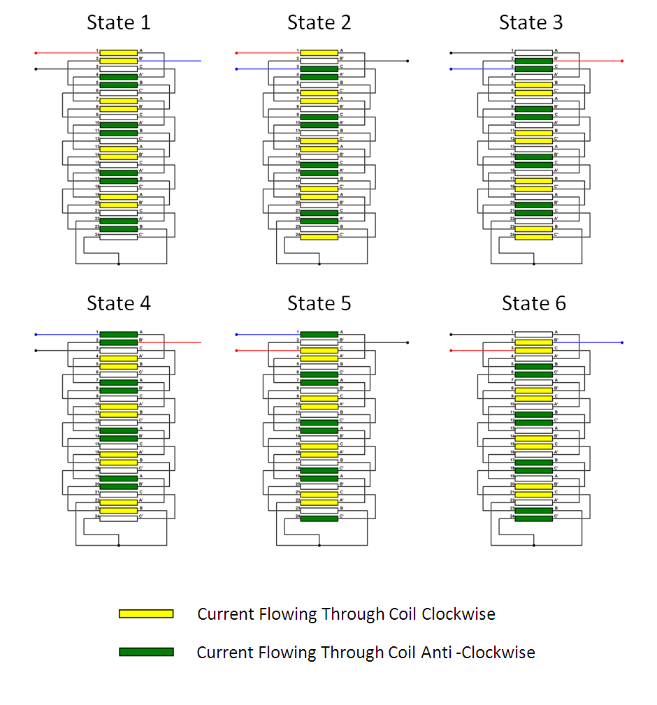
For the target mechanism, only two of three phases are ever powered at the same time111We have recently changed to powering three phases simultaneously., i.e. one phase is switched to provide the current source and another phase provides the return path. This operation is slightly different from the usual method of driving each phase with a phasor, but reduces complexity at the cost of only a small reduction in efficiency. With three phases, current can therefore be switched through the stator in six different ways. Using the external connection labels , and as shown in figure 30, these six states are: , , , , and . By stepping through these six states in a predetermined order, the coils can be switched to create a “ripple” motion in the magnetic fields generated within the stator, as illustrated in figure 31. The direction of motion is determined by the direction in which these states are stepped through; when reversing this order the ripple motion moves in the opposite direction. By tracking the position of the magnets and correlating this position to a given state, target motion can be achieved. The required order of the states to observe this apparent motion upwards through the stator is shown in table 1.
| State | Current Flow |
|---|---|
| 1 | |
| 2 | |
| 3 | |
| 4 | |
| 5 | |
| 6 |
6.3 Magnetic assembly and modelling
As described in section 3.3, the magnet assembly is composed of 3 radially magnetised rings, with a total length of 18 mm, matching the depth of 6 coils. This distance corresponds to the symmetry of the axial field, and alignment of the magnets with these fields gives the ability, with suitable feedback, to either hold the magnetic assembly in a predetermined position or to maximise the accelerating force on the permanent magnets.
A simulation of the interaction between the magnetic assembly and the coils was produced using a magnetostatic model in Opera 3D[20]. This simulates the stator in “State 4”. (The state is arbitrary due to the symmetry of the device.) The model is axisymmetric in R, z and the origin is placed at the centre of the stator, corresponding to a plane that sits on top of the 13th coil. For this model a current of 58 A was assumed to flow through the coils, approximately equal to the peak current during operation. The simulation ran over several iterations and, with each iteration, the magnetic assembly was moved in either 0.5 mm or 1 mm increments axially along the centre line of the stator over a total distance of 20 mm. The maximum force on the magnetic assembly was calculated for each position. The results are shown in figure 32, which shows a clear sinusoidal pattern for the resultant force on the magnetic assembly and a sine wave can be fitted cleanly to the simulation results. Although not illustrated here, the sinusoidal pattern of the force curve repeats every 18 mm, the length of one bank of coils. Further simulations confirmed that as the magnets move towards the end of the stator bore there is no deviation from this sinusoidal pattern, as the magnet assembly is always completely contained within the coil stack so end effects are minimal.
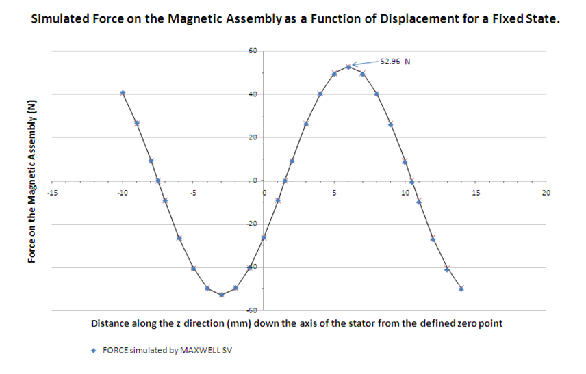
6.4 Zero-force points
From figure 32 it can be seen that there are two points for each repetition of the sine wave where the force on the magnetic assembly is zero. One of these zero-force points is unstable; movement of the magnetic assembly away from this point results in a force that pushes the magnetic assembly further away. However the other zero force point is stable, and movement of the magnets away from this zero-force point results in a restoring force; effectively, this point is the centre of a magnetic well. The stable zero-force points provide a mechanism by which the shaft can be levitated passively. The shaft will sit at an equilibrium position where the force of gravity is counteracted by the restoring force exerted by the magnetic force. Any small deviation from its equilibrium position would result in the shaft undergoing damped harmonic motion (where the damping would primarily come from the frictional forces between the shaft and the bearings). The drive is designed to be a high-acceleration device, accelerating the shaft in excess of 80 , so providing a force greater than , where is the mass of the shaft complete with magnets etc. Stable levitation occurs when the electromagnetic force on the shaft balances . To a good approximation the force scales linearly with the coil current so stable levitation of the shaft in close proximity to these zero-force points can be achieved with a current that is much smaller that that required to achieve the high accelerations needed to insert the shaft tip into the ISIS beam.
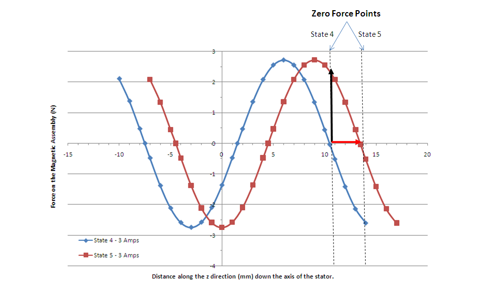
The zero-force points in figure 32 are shown for the stator in “State 4”. If the state sequence is progressed then the positions of these zero-force points move in step with the state sequence. Moving forward through the sequence moves the zero force points up through the stator in 3 mm increments, likewise moving backwards through the sequence moves the zero force point down the stator in 3 mm decrements. If the zero-force point is used to levitate the shaft then the target will track the movement of these zero-force points as the state sequence is progressed. When the state changes the shaft will move to the new point, as a restoring force will push the shaft to the new equilibrium position. This is illustrated in figure 33. The shaft will undergo damped harmonic motion as it settles at this new point.
The ability to move and hold the shaft in this way is utilised to control the target shaft position when the target is not actuating. For example by switching the coils to the appropriate state when the target system is powered up, the shaft is picked up from its resting position, also known as its “parked” position, and then moved to its holding position by progressing cyclically through these states. This final state, the “hold mode”, then holds the shaft indefinitely until actuation is required. Reversing the process allows the shaft to be lowered back down to its “park-mode”.
Using the stator in this way to control the shaft limits the “hold position” of the shaft to one of a set of predefined points that are 3 mm apart. This means that the hold position is not entirely arbitrary, but the 3 mm step size gives enough freedom to ensure that the shaft is held out of the ISIS beam. This system of moving the target shaft by allowing the magnets to track the position of the zero-force points is entirely passive and does not require any positional feedback to operate.
6.5 Actuation
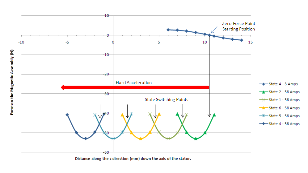
From figure 32 it can be seen that the zero-force point is half way between two maximum-force points; we define a maximum-force point as a position within the coil stack where the magnets on the shaft would experience a maximal repulsive force. For each set of two maximum-force points, one of them will push the magnets in one direction whilst the other will push the magnets in the opposite direction. Figure 32 shows that these maximum-force points are positioned 4.5 mm away from the zero-force points; this is of course true for any zero-force point in any one of the six possible states. It can be seen that the forces change very little 1.5 mm either side of the peak. Integration of the fitted sine wave 1.5 mm either side of the peak shows that the average force is 95.5% of the peak force. If the shaft was levitated at a zero-force point and the coil state was either to increment or to decrement by two states this would put the magnets 1.5 mm on the far side of one of the maximum-force points as the zero-force point would have been moved by 6 mm. The shaft would then accelerate back towards the shifted zero-force point. In either case the resultant force would cause the shaft to pass through the location of the maximum-force point during the first 3 mm of acceleration, as illustrated in figure 34.
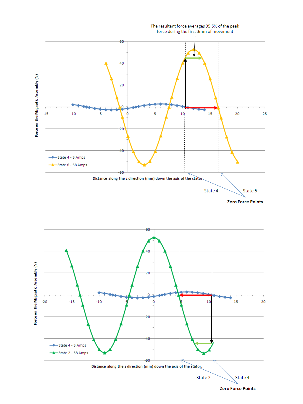
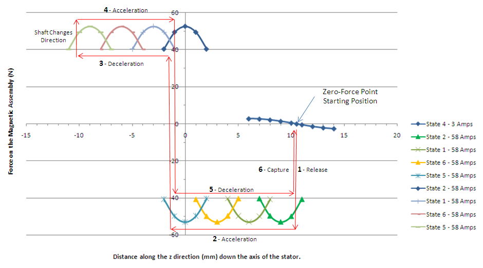
If, after switching the coil two states, no further switching was done the shaft would continue to accelerate towards the new zero force point 6 mm further up or down the coil stack and would execute damped harmonic motion about this point until it came to rest. However because the position of the shaft can be tracked using the optical quadrature system, another state change can be made when the target has travelled 3 mm, placing the magnets 1.5 mm on the far side of the next maximum-force point. This has the effect of maintaining a maximal accelerating force on the shaft. This process can be continued down the entire length of the coil stack as illustrated in figure 35. If the shaft is accelerated via this mechanism, deceleration can be achieved by switching the coil state by three positions. This has the effect of placing a force of equal magnitude but opposite direction on the permanent magnets. Once again, by referring to figure 32 and comparing this to figure 31, it can be seen that a switch of three states changes the direction of the accelerating force because it simply reverses the current flow through the coils. If a previously accelerated shaft is decelerated by this process then there will be a point where the shaft will change its direction of motion.
By monitoring the sense in which the position reading is changing, the quadrature system is able to determine the direction of motion of the shaft. A reversal of direction can be used as a trigger to capture the shaft at the nearest zero-force point at the end of an actuation. This is done by switching to a state that places a zero-force point close to the magnet’s current position. The coil pitch of 3 mm dictates that the shaft will never be more than 1.5 mm away from a possible zero-force point and so, providing the shaft does not have a high velocity, capture of the shaft at the zero-force point is inevitable.
The processes just described provide the necessary mechanism to accelerate the target into and out of the ISIS beam whilst enabling its capture again at the end of the cycle. Controlling the motion in such a manner is called “actuating”. The minimum positional resolution required to control the shaft in the way described is 1.5 mm whereas the optical system provides the position to within 150 . As will be described in the next section, the high resolution of the optical system allows better control of the stroke of the shaft. The use by the control electronics of the mechanisms described above is given in section 7, while figure 36 shows the principle employed.
6.6 Coil switching and current control
It has been shown that by wiring the stator in three phases and applying the appropriate currents to those phases it is possible to control the movement of the shaft. To do this effectively there are two principal design requirements. The first of these is the ability to switch current bi-directionally through any two of the three phases, and the second is the ability to control the amount of current that passes through the coils.
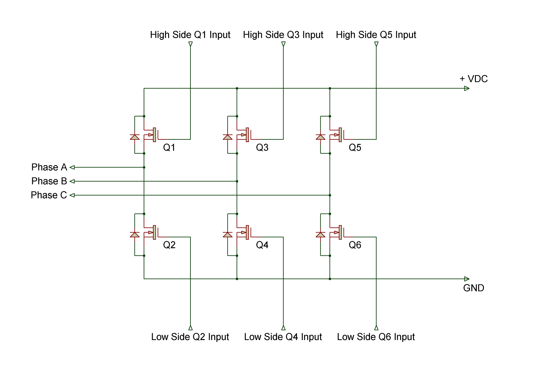
Bi-directional switching of the three phases of the coil stack can be achieved using six transistors arranged in three pairs, where each pair of transistors is connected together in series between the power rails of the power supply. The mid-point of each pair of transistors then connects to one of the three phase wires of the coil stack. Figure 37 illustrates how these transistors are connected. This type of circuit is known as a “Hex Bridge” or “Three Phase Inverter”. The three transistors across the top of the circuit are called the “high-side transistors” as they are connected to the positive power rail, while the other three are the “low-side transistors”. It is possible to see how this circuit can be used to switch the current bidirectionally through the phases by comparing table 2 with figure 37. The inputs are labelled Q1–Q6 in the figure.
| State | Current Flow | Hex Bridge Inputs |
|---|---|---|
| 1 | Q1 and Q4 | |
| 2 | Q1 and Q6 | |
| 3 | Q3 and Q6 | |
| 4 | Q3 and Q2 | |
| 5 | Q5 and Q2 | |
| 6 | Q5 and Q4 |
One risk that needs to be managed with this circuit is that if both transistors connected to a given phase are turned on simultaneously, e.g. if inputs Q1 and Q2 are activated simultaneously, then a short circuit is created between the power supply rails. This will permanently damage the transistors due to excessive current flow. This type of short circuit due to transistor switching errors is known as a “shoot-through”. Shoot-through is also possible if account is not taken of the time that it takes to switch transistors on and off. It is therefore necessary to ensure that the second transistor is only turned on after an appropriate delay. Shoot-through is not normally a problem when stepping through the state sequence in a circular fashion as there is always at least one state on a given phase between a low-side transistor turning off and the complementary high-side transistor being turned on (or vice versa). The minimum delay requirement is satisfied since the frequency of state changes is no more than a few kHz. However this is no longer true when the force direction is suddenly reversed. In this case both pairs of transistors experience a change in state and so a suitable delay must be imposed by the controller.
When the shaft is being levitated in its holding position the gravitational force will pull the shaft slightly away from the zero-force point such that there will be a small restoring force acting upon the shaft which exactly counters gravity. The amount of counter-force that the stator needs to supply to the shaft is small, reflecting the low mass of the shaft. Ideally this equilibrium position needs to be as close to the zero-force point as possible although a small offset can be accounted for. It can be seen from figures 33 and 33 that is maximal at the zero-force point so the amount of displacement required along the z axis to produce the restoring force is minimal and approximately proportional to the applied current over short displacements.
The amount of current passing through the coils needs to be large enough that the levitation is stable but small enough that power dissipation is minimised. A current of around 3 A has been found to satisfy these criteria. This can be seen from figure 34; the shaft, magnets and vane have a mass of 57 g so the gravitational force is about 0.56 N. This force is counteracted by the electromagnetic force at a displacement of 500 from the true zero-force point.
6.7 The target power supply
During actuation the shaft will be accelerated at 80 . It has been found that a coil current of 60 A is needed to obtain the required acceleration. This current, if sustained, would quickly overheat and damage the coils and so care must be taken to ensure that the actuation current is only supplied to the coil stack for the required amount of time. By pulse-width modulating the current through the coil stack, the average current that flows for a given duty cycle is, to a first approximation, linearly proportional to the maximum current that would flow through the device if the duty cycle were set to 100%. To ensure that enough overhead was built in to permit future upgrades, the power supply was specified to operate at up to 300 V and to provide a current of up to 100 A. The coil stack only requires the high currents for relatively short periods of time and the average current drawn is significantly lower than the peak current. It is therefore more economical and efficient to power the driving circuit from a capacitor bank which can provide the short, high-current pulses on demand. The capacitor bank is charged by an external power supply, designed to provide both the necessary charging current to top the capacitor bank up and the holding current. This capacitor charging unit or CCU effectively provides the average current that the stator uses, whilst the capacitor bank is there to provide the peak currents when required. The size of the capacitor bank attached to the hex-bridge is 70 mF and is rated to 400 VDC.
The use of a capacitor bank is inherently safer than a linear power supply because, should a fault occur that leaves the system in a state that demands high current, once the capacitor bank has discharged the current is limited to that provided by the CCU. The CCU used only provides a current of 4 A, and into a 3.6 load (the DC resistance of two phases of the stator at 20 ) this gives a power dissipation of only 60 W. This is significantly lower than the power dissipation during normal operation when actuating at 1 Hz and so limits the energy deposition into the coil stack. At 70 mF the capacitor bank stores a significant amount of energy. This energy could be deposited into either the coil stack or the bridge circuit under a fault condition. In order to reduce the voltage between any part of the coil stack and ground, a split supply providing V and +115 V is used (rather than 0 V and +230 V). This necessitates the use of two separate capacitor banks.
To switch the high currents necessary to drive the target drive, Integrated Gate Bipolar Transistors (IGBTs) are used. These transistors switch current quickly and saturate very close to the power-supply rail voltage due to a small internal resistance (). Both of these characteristics are good for minimising power dissipation within the transistors making them very efficient at transferring power to the load. By using these transistors a circuit that can switch a significant amount of power can be built with minimum footprint. The IGBTs that were chosen for the target power supply are power devices and can switch up to 250 A. All six sections of the gate drivers (one for each IGBT) are taken to a floating DC power supply as this gives better protection to the individual circuits. The logic circuitry that drives the gates on the IGBTs is supplied with power from a separate supply that is integral to the unit. Each of the two capacitor charging units uses a Xantrex 300-4, which can supply up to 4 A at up to 300 V.
Snubber circuitry has been added to the power supply to damp the high frequency transients created by the pulsed switching of the transistors. This also helps to stabilise the current flow through the motor and reduces electromagnetic noise emitted by the motor, its power supply cable and the driving circuitry.
6.8 System placement in ISIS
The power supply cannot be close to the target mechanism as the radiation produced by ISIS would be likely to cause premature failure of the electronics. It is also advantageous to have the electronics accessible so that power supply maintenance can be performed without having to wait for the synchrotron to be opened. The high currents required by the target mechanism and its low impedance mean that the distance to the power supply should be minimised to reduce ohmic losses in the power cable connecting the two together. For this reason the power supply has been installed on the outside wall of the synchrotron at a location as close to the target area as possible, requiring a cable length of 25 m. The control electronics for the target system are situated in the MICE Local Control Room, a significant distance from both the target and the power electronics. The distance between the control and power electronics is 70 m and that between the control electronics and the target drive is 100 m.
6.9 Fibre-optic links
The fibre-optic cables that run between the control electronics and the drive’s optical block have been discussed in section 5. Optical fibres are also used to transmit the six signals between the controller and the power supply. The use of optical fibres guarantees signal integrity, completely isolates the power supply from the controller and eliminates the risk of noise on the signal lines which could cause additional problems with either the controller or the transistor drivers in the power supply.
The fibre-optic link between the control and power electronics uses a commercially available optical transmitter/receiver pair. The transmitter is a high-power infra-red LED with a bandwidth up to 5 MHz. This is sufficient as a 1% duty cycle resolution on a 20 kHz PWM signal requires a bandwidth of 2 MHz. The receiver is a stand-alone unit that gives a TTL-compatible output for use in the hex-bridge driving circuitry.
The optical fibres used are the same multimode fibres used to return the laser light in the quadrature optical counter (BFH37-200). These fibres are well matched optically to the transmitters, and experiments in the lab showed lower losses using these cables than using the standard polymer cables that came with the transmitter/receiver pairs.
7 Target control
This section gives a description of how the target is controlled by the system electronics. The interface between the electronics and the computer that records the performance of the target, the Data Acquisition (DAQ) system, is also discussed. Figure 38 gives an overview of the major components of the target system and how they relate to each other as installed at the Rutherford Appleton Laboratory.
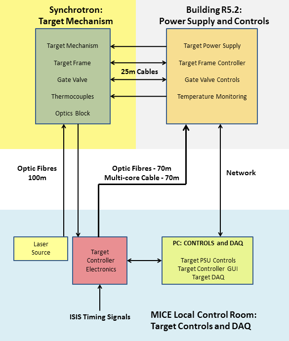
7.1 Target controller overview
The target controller is implemented on a Field Programmable Gate Array (FPGA). For the controller the logical units of the FPGA are configured to create a finite state machine (FSM) that both interfaces the controller to the outside world and controls the operation of the target mechanism. A Xilinx XC3S1000 Spartan-3 FPGA is used [21]. The FPGA has been bonded to a custom PCB that provides access to most of the FPGA’s IO pins and has a USB interface. The USB interface allows the FPGA to communicate with a PC, permitting soft control of the underlying FSM based upon its current state through a GUI interface. This FPGA/PCB combination has been used in other experiments and has proven to be reliable [22].
The four states defined for the target mechanism are Parked, Hold Mode, Actuate Enable and Actuating. These are illustrated in figure 39, with the paths which connect them. The job of the controller is to manage the movement of the shaft, ensuring that it is in the correct place for its given state, the correct state being dependent upon input from both external signals and the user. The controller’s FSM has many sub-states to ensure that the target operates correctly in a safe manner; this level of detail is not described here.
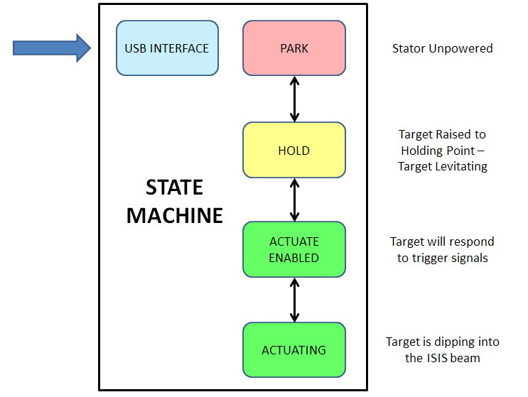
7.2 Control: park, hold and actuate enable modes
Before the target can be actuated it must be moved into its “hold” mode. When the shaft is lowered, its tip will intersect with the ISIS beam if the jacking frame is in its “in beam” position. Therefore, the controller is provided with interlocks to ensure that the shaft is in the hold position before the frame can be lowered and to cause the frame to be raised should the shaft move to the parked position when the jacking frame is lowered.
An enable key-switch on the front of the controller unlocks the system and permits it to receive control signals over the USB connection. Providing that all the interlocks are good, the controller can be commanded from the GUI to raise the shaft to its hold position. The latter is determined by a register value that is loaded over the USB interface and so is configurable in software. The default value is set to raise the target by 51 mm, enough to hold the tip out of the ISIS beam when the frame has been lowered. The holding position is achieved by advancing the zero-force point up the coil stack as described in an earlier section. Once the shaft has been raised to its hold position a check is performed to ensure that a correct count has been obtained by the quadrature counter and that an index signal has been received. An incorrect count or missing index signal could indicate a problem with the quadrature system and actuation would not then be possible.
The change of state from hold mode to actuate-enable mode reflects a change of the internal state of the controller which is initiated by the user from the control PC. However the system will not enter actuate-enable mode until the position counter reads an appropriate value, there are no other internal errors and all external interlocks are satisfied.
7.3 Control: actuation and capture
“Actuation” refers to the state when the stator is actively accelerating the shaft. Actuation is completed when the shaft has been electromagnetically recaptured at a zero-force point. Reliable capture of the target is essential to ensure it does not fall into the beam.
Actuation is performed actively; the coils are switched to provide the maximum force on the permanent magnets at all times during the actuation process. For this force to be maintained the coil switching has to track the position of the shaft and an accurate measure of the its position is essential. The actuation process goes through four distinct stages known as “quadrants”. The capture of the target is considered a separate process. The four quadrant states are shown in figure 40.
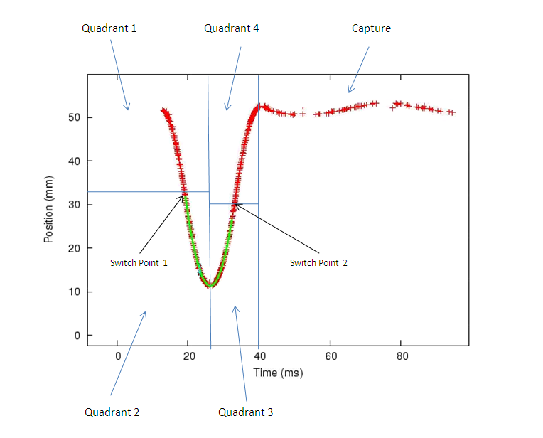
Upon receipt of a trigger signal, the control system enters “quadrant 1” of the actuate sequence. Here the controller causes the current through the coils to be switched such that the shaft accelerates downwards. The position of the shaft is tracked and the coils are switched to maintain the maximal force until the shaft reaches position “switch-point 1”. This is the position at which the coil currents are reversed and therefore determines the actuation depth. The position of switch-point 1 is calculated by the control software given the desired strike entered via the GUI. The strike may be controlled to a precision of 300 since the resolution of the quadrature system is 150 .
When the currents are reversed the shaft begins decelerating and the controller enters “quadrant 2”. The shaft is decelerated until it reaches the position where it changes direction as indicated by the quadrature counter. At this point there is no physical change to the system and the coil currents are kept the same; however this change in the shaft direction defines the point at which the controller state moves into “quadrant 3”. The shaft now accelerates upwards until it reaches the position defined by “switch-point 2”. Here the coil currents are reversed again and the shaft begins decelerating; this is accompanied by the controller state moving into “quadrant 4”. The shaft continues to decelerate and at the point where its motion changes direction again the controller enters the capture state. Because the shaft will have some small downward velocity by the time the change of direction is detected, it is necessary to reverse the current flow again for a short period of time, typically a few hundreds microseconds, to arrest the residual velocity. This “kickback” proved to be necessary for reliable target capture.
When the controller is in the capture state it calculates the location of the nearest zero-force point. It then switches the coils to place this zero-force point as close as possible to the shaft’s current location; the shaft is then left to be captured passively into this zero-force point. Ideally if “switch-point 2” is set to the correct value then the capture position should be the same as the hold position. If the zero-force point does not correspond to the hold position then after capture the shaft will be moved to the hold position ready for the next actuation.
Switch-point 2 is offset with respect to switch-point 1 because the decay on the capacitor bank means that the rate of acceleration in quadrants one and two is greater than that in quadrants three and four. Changing the strike changes both the switch points by an equal amount. If the value of switch point 2 is too high or too low, the shaft will be captured at either a higher or lower zero-force point. If under/over capture occurs persistently then the controller will automatically make a correction to the switch-point 2 offset until the shaft is being captured at the hold point. This system of quadrants to define the actuation cycle allows the shaft to be tracked accurately by the controller as it passes through the trajectory, ensuring reliable actuation.
7.4 The actuate trigger signal
The design of the actuate-trigger system is based on the following assumptions:
-
•
Actuation must be synchronised with the ISIS cycle and occur only when the MICE apparatus is ready to take data; and
-
•
The time at which the target intercepts the beam must be adjustable.
For a strike of 44 mm, the duration of the actuation cycle is approximately 30 ms. The shaft reaches the apex of its trajectory after 14–15 ms, the precise timing depending on the strike. The combined effects of gravity and the capacitor discharge cause the shaft to accelerate more slowly out of the beam than it accelerates into the beam.
The tip of the shaft is required to intersect the beam for the last 2 ms of the acceleration cycle. Since beam is extracted from the synchrotron 10 ms after it is injected, the actuation cycle must be initiated significantly before the start of this cycle. ISIS is able to provide a “machine start” (MS) signal that arrives up to 5 ms before the start of a cycle; however this provides insufficient time for the target to intercept the beam at the end of the subsequent cycle. A programmable delay is therefore used to trigger actuation in time to intercept a later cycle, the number of cycles’ delay being agreed in advance between ISIS and MICE. The ISIS operator monitors the beam loss produced by the target to ensure that the loss occurs only on the specific spills that the target is set to intersect. The number of cycles’ delay is chosen to be , where is typically 8. The delay is therefore set by the controller to be ms.
To optimise particle production for MICE while keeping proton-beam losses to acceptable levels, a fine programmable delay is used to tune the time within a spill at which the tip of the shaft intercepts the beam. Fine control of the time at which the shaft reaches the apex of its trajectory is required to compensate for the change in the trajectory of the shaft as a function of the strike. The deeper the target has to dip, the earlier it must be triggered.
8 Performance
8.1 Particle Production and Beam Loss
Several signals are provided by ISIS to allow MICE to verify that beam losses induced by operation of the target occur at the correct time and are within acceptable limits. These include the sum of the signals from the beam-loss monitors in sectors 7 (where the target is situated) and 8 (immediately downstream), the sum of the signals from all the beam-loss monitors and the outputs of the vertical and horizontal beam-position monitors closest to the position of the target[23]. These voltage signals are fed into a National Instruments (NI) 6254 PCI card [24] which samples the signals at 100 KS/s for 50 ms around the target actuation. The shaft position is also communicated to the card using a 10-bit parallel connection, and is recorded simultaneously with the voltage signals. The position is read at 200 KS/s to allow “deglitching” of the asynchronously-sampled parallel bits. The combined signal and position data are then both displayed online for real-time feedback and written to disk for later analysis. The recording of particle data is handled by the main MICE DAQ, enabling later comparison to the target data by matching appropriate timestamps.
For optimum operation the target mechanism must maximise particle production for MICE whilst simultaneously minimising losses in ISIS. The target achieves this by chasing the shrinking proton beam and only intercepting the beam during the final 2 ms of the acceleration cycle during which the pion-production cross section is the highest. Then, to prevent losses at the next ISIS injection 10 ms later, the target tip must be completely outside the beam envelope by this time.
Figure 41 shows the trajectory of the shaft together with the proton intensity. Two ISIS cycles are shown, the first spill being the one into which the tip of the shaft is inserted. Taking the arrival of the actuate-trigger as , the shaft begins to scrape the shrinking proton beam halo at 20 ms when small beam losses can be observed. The tip then intercepts the beam at around 22 ms and induces larger beam loss during the final 3 ms. The shaft finally moves out of the beam and reaches a safe distance of 58 mm before the next injection cycle at 35 ms. The position of the shaft tip at maximum insertion is normally measured relative to the nominal beam centre and this coordinate is referred to as Beam Centre Distance (BCD); as the target moves further from the beam this value increases.
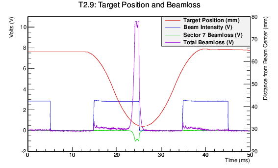
The particle rate in MICE plotted as a function of the beam-loss in sector 7 integrated over the acceleration cycle is shown in figure 42. The data were collected with the MICE Muon Beam set to deliver negative muons with a central momentum of 238 MeV/[8]. The figure indicates that the muon rate delivered to MICE depends linearly on the beam loss generated in the synchrotron. For a more detailed description of the dependence of particle rate on beam loss the reader is referred to [8] and [25].
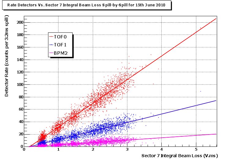
Figure 43 shows the integrated beam-loss in sector 7 plotted as a function of BCD. The minimum BCD which still yields acceptable beam-loss is 19 mm. At a BCD of 25 mm the target was capable of generating between 3 and 6 V.ms of beam loss depending on ISIS conditions. During routine operation in 2010 and 2011, a limit of 2 V.ms integrated beam-loss was imposed[26]. At fixed BCD, the beam-loss varies from run to run due to changes in ISIS beam conditions. The BCD is adjusted regularly to accommodate these fluctuations.
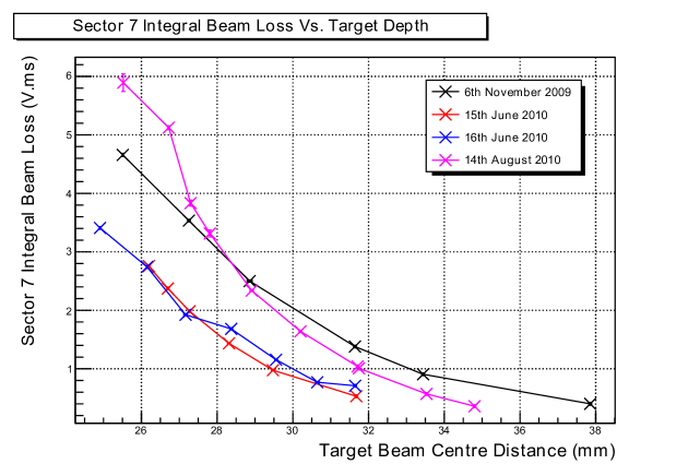
8.2 Target Lifetime
For operation on ISIS, the target must be capable of being operated reliably for periods significantly in excess of a typical User Run, typically of six-weeks duration. The system is monitored to identify the early signs of wear as a damaged or malfunctioning target would disrupt the smooth running of ISIS and prevent MICE from taking data. Wear on the Vespel bearings limits the lifetime of the target mechanism to millions of actuations. The bearings are buried deep within the stator body preventing direct visual inspection and monitoring. Therefore, indirect techniques have been developed to monitor the performance of the mechanism and the wear on the bearings.
8.2.1 Monitoring
Monitoring the mechanical performance of the target mechanism is performed using a list of key values returned from the controller after each actuation. This list includes data from the actuation, such as the time to reach switch-point 1, the minimum position reached and any errors which occurred. This information is ideal for long-term monitoring because it contains only key values, reducing the volume of data and the processing time. In addition, since the data is calculated by the control algorithm during actuation it is much more precise and flexible than that collected by the NI card. The data is analysed offline using a simple ROOT[27] script to study the variation in performance as a function of time.
8.2.2 Bearing Performance
The bearing performance is monitored using two key parameters. The first is the acceleration of the shaft, since any increase in friction will also cause a decrease in acceleration. This is calculated from the start of the actuation to the first switch-point (see figure 40), since the velocity of the shaft at this point ensures a good time-resolution. Unfortunately, any change in the voltage or temperature of the coils also has an effect on the coil current and therefore on the acceleration. To help reduce these effects the capacitors are charged to a fixed voltage (115 V) and the temperature of the coils is recorded. Figure 44 shows the drop in acceleration over time as the bearings wear.
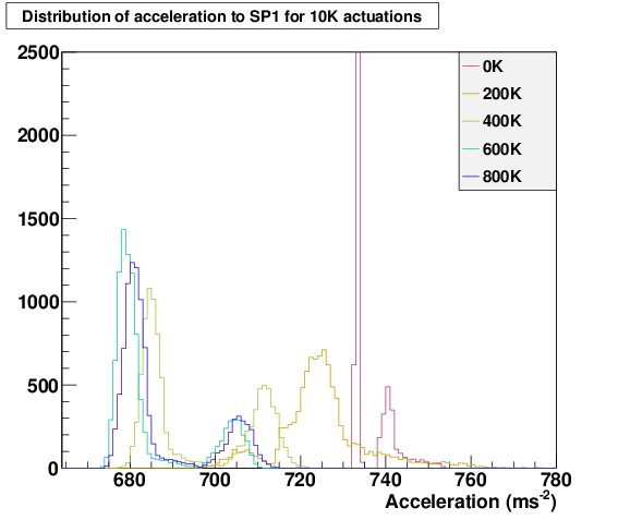
In addition to decreasing acceleration, the greater friction also allows the shaft and magnets to be captured and held further from the zero-force point at the centre of the magnetic potential (see section 6.4). This can be observed at the beginning of the next actuation when the shaft position is displaced from its normal starting location. This effect is monitored over time by plotting the distribution of starting positions for several hundred actuations and calculating the full width. Figure 45 shows the increase in the full width of the starting position. The increasing jitter on the starting position also causes variation in the BCD due to the symmetry about set-point 1. An increase in jitter in BCD will increase the variability of the generated beam-loss and hence makes it more likely that the this value exceeds the amount permitted by ISIS for that run.
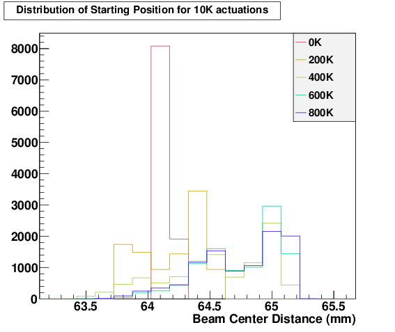
8.2.3 Test Programme
To aid in understand bearing wear, develop monitoring techniques and improve bearing life an extensive test programme has been undertaken. The nomenclature used to identify the target version is T, where corresponds to the stator number and corresponds to the shaft/bearing combination. For testing, stator 2 was used, as stator 1 was installed inside ISIS. Each test used a freshly-machined set of VESPEL bearings. For maximum wear, the largest strike of 45 mm (corresponding to 19 mm BCD) and a high dip rate (0.83 Hz) were used. For comparison, operation in ISIS typically runs at rate of 0.4 Hz and with a strike of 36 mm.
Table 3 shows a summary of the bearing tests on stator 2 since the development of the FPGA-based control system. The first system tested was T2.4, which had a fully quality-assured DLC-coated shaft and a set of VESPEL bearings. The test ran for approximately 3 weeks and was disassembled at weekly intervals to check for dust. The test was terminated at 1 million actuations when the shaft began to lock up due to wear in the anti-rotation component. This was resolved by cutting semi-circular reliefs out of the bearing as described in section 4.2.3, which was implemented in the subsequent test T2.5.
| Test | Actuations (K) | Run | Acceptable | Comments |
| mode | for ISIS? | |||
| T2.4 | 1,000 | WI222Weekly Inspection. The target was disassembled on a weekly basis to monitor the dust produced by the bearing wear. | Y | Well-polished shaft, occasional sticking |
| during capture (outside ISIS). | ||||
| T2.5 | 4,000 | WI | Y | Weekly inspections caused a |
| noticeable disturbance to performance. | ||||
| T2.6 | 1,100 | DS333Daily Stop. Once a day the mechanism is stopped for an hour to let the system cool and thermally contract. | Y | Tight bearing-clearances. Sticking during |
| capture noted at end of run. | ||||
| T2.7 | 1,300 | DS | Y | Clearances re-matched to T2.5, minor |
| increase in time before sticking during capture. | ||||
| T2.8a | 1,000 | DS | Y | Further increase to bearing-clearance, sticking |
| began near 1 million actuations. Test paused | ||||
| for controller update to help alleviate sticking. | ||||
| T2.8b | 1,000 + 1,500 | DS | Y | T2.8 test resumed with an updated controller |
| and enabled a further 1.5 million actuations. |
The next test, T2.5, was set up identically to T2.4 and ran for over 8 weeks and 4 million actuations. Each week the bearings were inspected for dust and a small, but noticeable, amount built up over time (see figure 46). In the monitoring of acceleration and starting position, a performance increase was noticed after the disturbance caused by each inspection. Such disturbance is not possible in ISIS and the weekly inspections were abandoned in future tests.
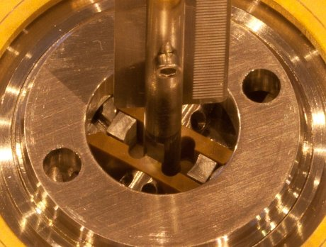
The tests of T2.6, T2.7 and T2.8 all ran without intervention and with a daily stop of one hour to allow the target to cool and more closely mimic operation in ISIS. Each test had slightly different bearing clearances, but all exhibited similar performance. The full width of the starting position is shown in figure 47, which can be seen to broaden steadily over time with T2.7 broadening slowest. All the tests ran reliably up to 1 million actuations, but after this the capture of the shaft began to be outside the defined limits. The controller is normally able to apply a low-force correction to move the target into the correct location before beginning the next actuation. However, the increased friction in the bearings caused the shaft to become stuck in this state, so an improved control algorithm was put in place for T2.8b. As the update was merely to the controller, the target was not disturbed during the upgrade procedure and testing was resumed after the controller update. The improved algorithm provided a larger force during capture and allowed T2.8b to perform a further 1.5 million actuations without inspection, bringing the total to 2.5 million actuations.
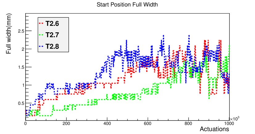
In the final inspection of the tests T2.4 through to T2.8 there was very little dust observed inside the drive, demonstrating the suitability of VESPEL bearings for use on ISIS. This enabled the DLC-on-VESPEL design to be approved for use in ISIS and T2.9 was used to replace T1.0, the target previously in operation on the accelerator.
9 Summary
A mechanism has been presented which accurately inserts a small target into the halo of the ISIS proton beam, to generate particles for the Muon Ionisation Cooling Experiment[3],[8]. The heart of the device is a linear motor consisting of an array of radial permanent magnets inside a water-cooled bank of flat coils. The magnets are mounted on a titanium shaft, the tip of which forms the target. With appropriate remote position sensing and control of currents through the coils, accelerations of over 780 m s-2 are achieved during actuations, while the target remains magnetically levitated between insertions. Isolation mechanisms are implemented so that, in the case of a fault, the drive can be separated from the synchrotron both mechanically and from its vacuum system.
The most challenging part of the design has proved to be the sliding bearings which constrain the motion of the shaft. The solution adopted uses a diamond-like carbon coating on the shaft engaging with polyimide inserts. The target drive has been tested both outside and inside the synchrotron, and detailed performance data have been recorded. Reliable operation has been demonstrated for several millions of actuations. Beam loss caused by the target has been monitored, and the particles produced have enabled the operation of the MICE experiment.
Acknowledgements
We gratefully acknowledge the ISIS Division at the STFC Rutherford Appleton Laboratory for the warm spirit of collaboration and for providing access to laboratory space, facilities, and invaluable support. We are indebted to the MICE collaboration, which has provided the motivation for, and the context within which, the work reported here was carried out. We thank Dr. N. Schofield of the School of Electrical and Electronic Engineering, University of Manchester (and formerly of University of Sheffield) for his design of the original linear motor, Dr. W. Lau of Oxford University for studies of vibrational modes of the target and Emily Longhi of STFC/Diamond for initial magnetic field mapping. We would like to acknowledge the work of TecVac of Cambridge in the development of diamond-like carbon coatings of the shaft and prototype bearings, Excel Precision of Gloucester for accurate spark erosion of the lower-shaft bore and the apertures in the vane, and Multigrind Services Ltd of Rickmansworth for precise grinding of the upper shafts.
This work was supported by the Science and Technology Facilities Council under grant numbers PP/E003214/1, PP/E000479/1, PP/E000509/1, PP/E000444/1, and through SLAs with STFC-supported laboratories.
References
- [1] S. Geer, Neutrino beams from muon storage rings: Characteristics and physics potential, Phys. Rev. D57 (1998) 6989–6997, [hep-ph/9712290].
- [2] D. Neuffer, Multi-Tev muon colliders, AIP Conference Proceedings 156 (1987), no. 1 201–208.
- [3] MICE Collaboration, G. Gregoire et al., An International Muon Ionization Cooling Experiment (MICE), MICE Note 167 (2003) [http://mice.iit.edu/mnp/MICE0021.pdf].
- [4] “ISIS pulsed neutron & muon source.” http://www.isis.rl.ac.uk/.
- [5] Rutherford Appleton Laboratory (RAL). http://www.scitech.ac.uk/About/find/RAL/introduction.aspx/.
- [6] MICE Collaboration, “MICE technical reference document - draft version.” http://www.isis.rl.ac.uk/accelerator/mice/TR/MICE_Tech_Ref.html, 2005.
- [7] eds. S. Ozaki, R. Palmer, M. Zisman, and J. Gallardo, Feasibility study-II of a muon-based neutrino source, BNL-52623 (2001) [www.cap.bnl.gov/mumu/studyii/FS2-report.html].
- [8] MICE Collaboration, The MICE muon beam on ISIS and the beam-line instrumentation of the Muon Ionization Cooling Experiment, JINST 7 (2012) P05009, [1203.4089].
- [9] N. Schofield, C. Booth, and P. J. Smith, A low mass, brushless permanent magnet linear actuator for the ISIS target accelerator, in 50th Annual Conference on Magnetism and Magnetic Materials (MMM05), 2005. (Paper FF-12).
- [10] “P.A.R. Insulations and Wires Ltd. Technical data MAGNETEMP CA-200.” http://www.par.gb.com.
- [11] “P.A.R. Insulations and Wires Ltd. Technical data DOLPHON-2102.” http://www.par.gb.com.
- [12] L. Howlett, “Simulation of radiation levels in the MICE target magnets.” MICE Note 166, 2007. http://mice.iit.edu/micenotes/public/pdf/MICE0166/MICE0166.pdf.
- [13] A. Fasso et al., FLUKA: a multi-particle transport code, 2005. CERN-2005-10, INFN/TC-05/11, SLAC-R-773.
- [14] DIN 65084:1990 Aerospace; Heat treatment of wrought titanium and titanium alloys.
- [15] “Specification for material selection and the cleaning of components for use in the ISIS synchrotron systems.” Rutherford Appleton Laboratory note ISIS/TS/NS/04.
- [16] “Vespel® SCP-5000 polyimide isostatic shapes typical ISO properties.” DuPontTM data sheet.
- [17] “630 nm single mode fibre.” ThorlabsTM data sheet http://www.thorlabs.com/Thorcat/12600/12606-s01.pdf.
- [18] “0.37 NA hard polymer-clad multimode fibre.” ThorlabsTM data sheet http://www.thorlabs.com/Thorcat/12200/12255-s01.pdf.
- [19] “H3R880IR - FDH3 housing with FDR880IR pin photodiode.” Farnell data sheet http://www.farnell.com/datasheets/99561.pdf.
- [20] Ansoft, “MAXWELL SV. the student version of MAXWELL 2D.” http://www.ansoft.com/maxwellsv/.
- [21] “Xilinx Spartan-3 FPGA.” http://www.xilinx.com/support/documentation/user_guides/ug331.
- [22] “The SPiDeR Collaboration, note=https://heplnm061.pp.rl.ac.uk/display/spider/Home/.”
- [23] S.Payne et al., Beam diagnostics at ISIS, Proceedings of HB2008 (2008) 466.
- [24] “National Instruments 6254 PCI card.” http://sine.ni.com/nips/cds/view/p/lang/en/nid/14126.
- [25] A. Dobbs, Particle Rate and Host Accelerator Beam Loss on the MICE Experiment. PhD thesis, Imperial College London, 2011.
- [26] MICE Collaboration, D. Adams, R. Edgecock, I. Gardner, and K. Long, Pion measurements with the HEP test beam and implications for MICE, MICE Note 217 (2008) [http://mice.iit.edu/micenotes/public/pdf/MICE0217/MICE0217.pdf].
- [27] R. Brun and F. Rademakers, ROOT - an object oriented data analysis framework, Proceedings AIHENP’96 Workshop, Lausanne, Sep. 1996, Nucl. Inst. & Meth. in Phys. Res. A 389 (1997) 81-86. See also http://root.cern.ch/. (1996).