Pinch-off of underwater air bubbles with up–down asymmetry
Abstract
Topological singularities occur in a broad range of physical systems, including collapsing stars and pinching fluid interfaces. They are important for being able to concentrate energy into a small region. Underwater air bubbles in particular appear in many practical applications, including new technologies to reduce skin drag on cargo ships. Previous theories show that just before an air bubble pinches off, the neck looks like a cylinder at its very smallest point. Unusually, however, the neck approaches this shape so gradually that the theoretical cylinder solution is not reached in practice; the singularity spends its entire lifetime in a transient phase. Therefore, in order to understand the evolution, we study the transient effects in detail. This paper details the simulation results of bubbles with initial conditions far from the cylindrical solution: squat, up–down asymmetric neck shapes, with imposed vertical flow. We find that the asymmetry is transient: the neck quickly shifts vertically to become up–down symmetric. Importantly, we find that the resulting symmetric singularity is a blend of the initial top and bottom sides, with a weighting factor that is tunable by adjusting the airflow through the neck. This effect should have implications for the later stages of evolution, including the generation of satellite bubbles and the formation of the Worthington jet.
Physics Department and the James Franck Institute, University of Chicago, Chicago IL 60637
1 Introduction
Non-linear continuous media can produce finite-time singularities, where a physical quantity nearly blows up in a fixed amount of time. In practice, the system never becomes fully singular; new forces become important at small scales and cut off the singularity. Examples of physical singularities include black hole formation, supernova explosion, crack propagation, and fluid pinch-off. Here, we study a singularity that occurs when an underwater air bubble pinches off from its air source. Despite the small energies involved, the pinch-off produces a small region of water moving at speeds of 10s of meters per second (Plesset & Prosperetti, 1977). Many of the interesting features of bubble pinch-off apply to implosion-type singularities in general.
Bubble pinch-off also has practical applications itself. For example, McCormick & Bhattacharyya (1973) discovered that injecting air bubbles under the hull of a ship reduces skin drag. Only recently has the idea been implemented on commercial ships, resulting in an overall 5-10% fuel savings (Ferrante & Elghobashi, 2004; Kawabuchi et al., 2011). The drag reduction depends on the size distribution of the bubbles, which in turn depends on the specifics of pinch-off (Longuet-Higgins et al., 1991; Gordillo & Fontelos, 2007). Also, the bubbles can pinch apart in a turbulent flow, generating acoustic emissions (Frizell & Arndt, 1987) and dispersing into a distribution of smaller bubbles, which depends on the details of pinch-off (Lasheras et al., 2002). The mechanisms controlling bubble pinch-off are size-independent and also govern the breach of a submarine hull (Ikeda et al., 2009), and the violent whoosh behind an object plunged into water (Bergmann et al., 2006). This paper focuses specifically on the effects of up–down asymmetry in bubble dynamics. Up–down asymmetry is present in nearly all bubbles due to the hydrostatic pressure gradient. In general, the bottom portion of the neck is more slender than the top due to the hydrostatic pressure. This effect can be exacerbated if the bubbles are generated in a dynamic stream of water (Oğuz & Prosperetti, 1993). In fact, this research has potential implications for the jet of water that shoots upward after such an impact, called the Worthington jet after Worthington & Cole (1897), (Gekle & Gordillo, 2010). §5 discusses how the initial conditions of the cavity determine the bubble shape just before the impact that spawns the Worthington jet.
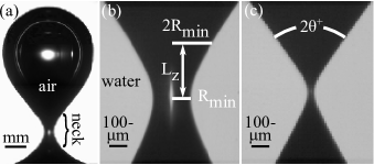
Few people realise that they are creating a singularity when they blow a bubble into a glass of water using a drinking straw. In experimental set-ups, the effect can be controlled by precisely pumping air into a pressurised nozzle (see figure 1a). As the air rises, surface tension competes with buoyancy to create a quadratic neck shape. Then, the neck becomes unstable and water rushes in from all sides to close it off. This sets up the regime we study in this paper, where the inertial flows diverge in speed where they are closing the shrinking neck, dominating all other forces and creating a singularity. If this regime were allowed to continue unaltered, the neck would approach a long-and-slender cylinder, with purely radial flows (Longuet-Higgins et al., 1991). Before this occurs, however, fast air-flows develop in the neck, potentially altering the collapse scaling (Gordillo et al., 2005; Burton & Taborek, 2008). Eventually, the air even goes supersonic (Gekle et al., 2010). Just before the airflow effect, some authors including Gordillo et al. (2005) and Keim (2011) measure a small residual asymmetry that influences the air flow. This is consistent with our results that the initial asymmetry decays as a power law, but is still measurably appreciable after at this scale. Finally, Keim et al. (2006) found that if the bubble is not quite axisymmetric to begin with, the deviation actually becomes more pronounced as the neck approaches pinch-off. The outcome is a side-to-side contact before the average radius reaches cutting off the singularity. These vibrations were confirmed and studied in detail in later theory (Schmidt et al., 2009), experiments (Keim, 2011; Enríquez et al., 2011), and simulations (Turitsyn et al., 2009; Lai, 2012).
This singularity is unusual in that it reaches the cut-off point before the neck shape has a chance to reach its predicted end-state shape, which is a long cylinder (connecting slender cones on the top and bottom, see §2). Most singularities with a unique end-state shape (universal singularities) rapidly approach that shape with power-law dependence (Shi et al., 1994). In those cases, the transient effects leading up to the universal shape are short-lived and ignorable. In contrast, the air bubble neck shape evolves very gradually as a function of the neck radius only going as (Gordillo et al., 2005; Eggers et al., 2007; Gekle et al., 2009). Indeed, the transition is so slow that on observable length scales the neck never appears cylindrical, but rather as two relatively squat cones, smoothly connected (see figure 1b-c). Although technically universal, this singularity spends its lifetime in the transient phase. Therefore, this paper explores the various transients that can occur in evolution.
We begin by exploring the effect of highly distorted initial neck shapes, including necks with large curvature and up–down asymmetry. We found that the asymmetry is truly transient in every sense: it vanishes after only several factors of decrease in the minimum radius. The neck undergoes this transition not by flexing the cones, but by shifting the vertical position of the pinch-off. By shifting instead of readjusting in place, the (new) collapse region rapidly becomes nearly up–down symmetric. Then, the neck goes through a phase of being symmetric but also squat, with significant (symmetric) vertical flows (Herbst & Zhang, 2011). Depending on where the neck shifts vertically, the symmetric squat neck inherits its dynamics from either its top or bottom side, or a blend of both. Interestingly, we found that by tuning the initial vertical flow near the neck, we could adjust the degree of this blending. This effect may explain some of the late-stage effects seen in experiments that tune the density of the inner gas (Burton & Taborek, 2008; Keim, 2011). When the bubble is in the formation stage, gas rises through the neck. Denser gasses impart more momentum to the neck area, giving the neck an initial vertical velocity component. We predict that this should cause the neck to inherit its aspect ratio from the top side, which is more squat. Burton & Taborek (2008) do in fact see more squat end-state neck shapes for higher gas densities (up to their observed critical density). Keim (2011) observes that the very early stage air flow during formation sets up a water velocity field, which then evolves independent of the air during the inertial stage studied in this paper. He also confirms our observations that the water flow affects the up–down symmetry and neck position later in the evolution. Neither experiment, however, attempted to manipulate the initial neck velocity field purposely, except by altering the gas density. Given our simulation results, it should be worthwhile to explore more deliberate ways of controlling the initial airflow through the neck, for example by blowing the bubble with a top and bottom nozzle simultaneously.
§2 summarises the previous research on the inertial stage of the bubble singularity, and the need for looking at up–down asymmetry separately. §3 gives an overview of the computational methods used to perform the studies. The results are divided into two sections for ease of reading: §4 gives a full description of a typical collapse. §4 describes how the initial flow field, specifically the vertical velocity gradient, can be used to tune the details of the final collapse. §5 concludes with a discussion of how the results could be seen in experiment, and problems that remain unsolved.
2 Background
The first stage, described in §1, sets up the initial conditions for the implosion, and involves the interplay between surface tension and buoyancy. After this point, surface tension becomes dwarfed by inertial forces. This is the point where we begin our simulations, and we assume inviscid flow with only inertial and pressure forces.
We use the common assumption that the water’s velocity field is incompressible irrotational and decays to zero far away.
We add another assumption that the air in the bubble is dynamically passive, with a uniform pressure whose value ensures constant bubble volume in time. Experiments show that after the neck begins to collapse, airflow is unimportant until the neck radius reaches roughly 100 µm (Burton & Taborek, 2008; Keim, 2011). Around that point, airflow through the neck becomes relevant and our assumption breaks down. Soon after, neck vibrations dominate. Here, we will only study what happens up to this point, assuming an axisymmetric bubble with uniform air pressure.
Being curl-free, the velocity can be described by a scalar potential, defined as Since the exterior flow is incompressible, implies
| (1) |
That is, Laplace’s equation governs the potential in the bulk. This allows to be solved everywhere in the exterior given on the interface. Equating the relevant stresses on the interface gives a non-linear differential equation for on the surface of the bubble, first-order in time and space:
| (2) |
where is the water density. The previous two equations determine the evolution of the velocity field. The velocity field in turn determines how the interface evolves. Surface elements are advected by the local velocity on the surface,
| (3) |
Previously, the solutions to equation 2 were only studied carefully in the up–down symmetric, long-and-slender limit (Gordillo et al., 2005; Eggers et al., 2007; Gekle et al., 2009). These solutions produce elegant, analytic results showing the neck approaching a cylinder logarithmically slowly as . There are differences between the theories, but each assumes a (time-dependent) purely radial flow. This is equivalent to saying that the potential distribution is proportional to the zeroth order cylindrical harmonic:
| (4) |
where is a length scale related to the system size, and is related to the rate of inflow, and is determined by equation 2. For a perfectly cylindrical neck with constant and the reader may verify that satisfies the governing equations. In most cases, the pressure term is negligible, leaving which is nearly constant. This defines a flow, that evolves the neck gradually towards a cylinder. If were instead constant, Longuet-Higgins et al. (1991) found that any parabola-of-rotation would generically evolve into a hyperbola-of-rotation. Indeed, at late stages the bubble neck shape does resemble a hyperbola-of-rotation by the fact that the neck looks like two smoothly connected cones (figure 1c), which we classify by top and bottom opening angles, and respectively. For consistency, we actually measure an effective cone angle defined by Taking into account the logarithmic dependence of on the cone opening angles decrease very slowly to approaching a cylinder. Even at the small scale of figure 1c, the cone angle is approximately Even under ideal conditions the neck does not become cylindrical before neck vibrations tear off the bubble.
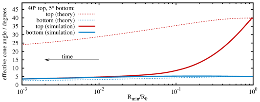
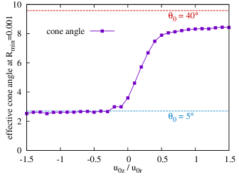
There are two problems with analytic solutions of the form in equation 4. First, they only apply when the neck shape is long-and-slender and up–down symmetric. Neither assumption holds for real bubble necks (see figure 1). The theory predicts qualitatively incorrect behaviour for initially up–down asymmetric necks (figure 2). In the theory, the neck shape evolves as a stack of non-interacting cross sections, each one governed by equation 4 (or similar). In reality, vertical interaction plays a large role in the shape evolution. Without vertical flow, the asymmetry decays logarithmically slowly. With vertical flow, we find that the asymmetry vanishes as a power law (measured to go as
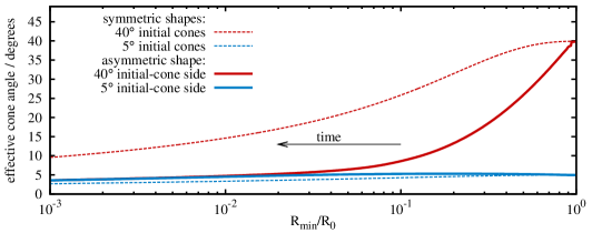
In fact, for up–down asymmetric shapes, the most important effect comes from the global interaction between the top and bottom sides. If we artificially forbid flow through the mid-plane, the up–down asymmetry no longer vanishes quickly (figure 3 dashed lines). §4 describes the mechanism in detail. In short, the singularity shifts vertically in the direction of the smaller cone angle, and in doing so equalises the cone angles. §4 shows that this effect can be manipulated. By introducing a vertical flow to the initial conditions, the vertical position of the neck can be tuned. In doing so, the resulting symmetric neck inherits a different blend of characteristics from the top and bottom sides. This effect should be realisable in experiments by adjusting the air flow rate through the neck during the initial set-up phase.
3 Methods
To Solve equations 1-3, we use the standard procedure of reformulating the equations as a boundary value problem, where the bulk differential equation becomes a surface integral equation. This requires two steps. First, the ordinary derivative in equation 2 is replaced by the co-moving derivative and will apply to the fluid parcels that constitute the surface. Second, equation 1 is reformulated using Green’s integral:
| (5) |
where is a fixed point on parameterizes the surface, and is the unit surface normal at pointing into the bubble.
With both governing equations defined on the interface, the formulation reduces to 2 dimensions. We further reduce to 1 dimension by assuming axisymmetry. At each time step, we use cubic splines to interpolate the discrete surface nodes . Then, for each we allow to take the place of in equation (5). We use Gaussian quadrature to perform the integral over segments connecting adjacent spline midpoints with the first and last segments being only half splines. Thus, the instances of equation 5 can be schematically written as where and are -by- matrices and Therefore, given on the surface we have and where is an infinitesimal arc length. Using we advect the N nodes using and evolve using equation 2, completing the cycle (Pozrikidis, 1997; Oğuz & Prosperetti, 1993). The pressure can be solved for explicitly after evolving the shape and before updating (formula and derivation available upon request).
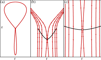
In order to accurately resolve the pinch-off dynamics, we found it important to use a node distribution scheme that maintains a gradual variation in the spacing between node points and that continually adds nodes in the neighbourhood of the minimum (see figure 4). At each moment, if the vertical distance between nodes exceeds a maximum spacing in the region where the neck radius is less than we add a new node at the midpoint of that spline. After experimenting with several functions for we found allows the simulation to accurately track the dynamics 111For the up–down asymmetric case, we define the current height of the neck minimum as and for (reverse superscripts for .
We begin the simulation by specifying an interface shape and velocity field. In general there are an infinite number of each. Here, we examine generic smooth distributions. To expedite the computation, we do not prescribe a purely quadratic shape profile at but instead use the result from previous studies that a slender quadratic neck evolves into a hyperbola, and prescribe:
where is the opening angle of the cone, and is height from the neck minimum to the end of the bubble.
To initialise the velocity field, most previous research uses a pure radial collapse, because it is the counterpart of the cylindrical end-state solution. We use this as a starting point. Equivalently, we prescribe a line of point sinks along the z-axis:
We use much larger than the neck region, to avoid end effects. For §4, we also add a vertical velocity component to the initial conditions of the neck region. One trivial possibility is a uniform vertical component. That would be the same, however, as just boosting the neck region to a new reference frame and the pinch-off would be identical, only boosted. Instead, we use the following form, which consists of a line of sinks (sources) along the z-axis that vary in strength proportional to height
| (6) | |||||
where and the limit is taken for points on the z-axis. This field acts as a stretched out dipole. The total initial potential field consists of a weighted sum of the line sink and the dipole field:
| (7) |
where The terms in parentheses are normalisation factors, so that the initial velocity at the neck minimum has radial and vertical components and respectively. This initial velocity field has the added benefit of resembling the effect of vertical airflow through the neck on the surrounding water.
4 Results
Our simulations show that the evolution of the neck towards singularity depends critically on both the initial neck shape and the initial velocity field. We show the two effects separately.
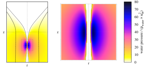
§4 details how an up–down asymmetric shape evolves with a simple initial velocity field: pure radial flow. The velocity field immediately develops a pressure ring just outside the neck region, but below the neck minimum itself (in general, towards the side with smaller cone angle). As the pressure peak moves inward, it bulges the shape inward, shifting the vertical location of the neck minimum and making the neck symmetric. The symmetric neck then progresses as a symmetric collapse, with the upper cone angle adjusted to match the bottom.
§4 adds the effect of initial vertical flow around the neck. A small upward flow is enough to oppose the neck from shifting downward. After becoming symmetric, the neck is a blend of the top and bottom cone angles. This gives a possible experimental method for adjusting the cone angle of the neck at pinch-off.
Shape Asymmetry
We studied many different combinations of initial top and bottom cone angles and respectively), with each angle ranging between and along with different initial velocity distributions. The results are qualitatively the same for any combination of top and bottom cone angles, but the asymmetric effects become more pronounced for larger asymmetry. In this section, we use a neutral radial inflow (equation 7 with ), and an initial top cone and bottom cone.
The initial shape consists of the neck, a hyperbola-of-rotation with the given cone angles, rounded off by large end-caps (figure 4a). Immediately after the simulation starts, a ring of high pressure develops in the water surrounding the neck, but slightly below the initial neck minimum. This causes the shape to bulge in at a height below the original neck minimum (figure 4b), and the position of the neck minimum to descend. In our extreme example, the descent occurs so fast that a new neck actually forms, which appears as a jump in the neck’s vertical position (figure 4b). Meanwhile, the pressure peak continues to grow in strength and become more symmetric (figure 5). The neck minimum shifts downward at roughly a constant rate (lab frame) until pinch-off (figure 4b). This constant vertical rate is soon overcome by the large radial implosion flow, and becomes insignificant at later times (figure 4c). By this time, the neighbourhood of the neck is completely symmetric, and the system undergoes the previously-studied symmetric collapse. In this process, the top side of the shape performs most of the accommodation to match the bottom side, and the large initial upper angle has little effect after the transient (figure 3).
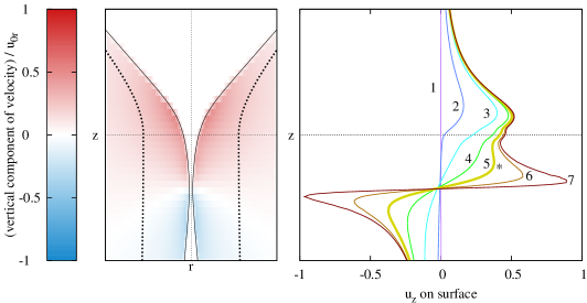
The process can be seen in more detail by studying the evolution of the velocity field, specifically the vertical velocity. Initially, no vertical flow is present (figure 6 curve 1), but immediately an asymmetric straining flow develops (figure 6 curve 2). Soon afterwords, the origin of the straining flow shifts downward (figure 6 curve 3). Driven by the pressure ring, the straining flow becomes symmetric (figure 6 curve 4), which in turn makes the neck shape symmetric. Eventually, the vertical velocity forms a local maximum in on the upper side (figure 6 curve 5, indicated by ’*’). From then on, the straining flow grows asymptotically strong, leaving behind only vestiges of the original top side, which stagnate and become insignificant (figure 6 curves 6-7). The transition from curve 2 to curve 4 shows that the top part of the straining flow adjusts to match the bottom half through a downward shift of the straining flow centre.
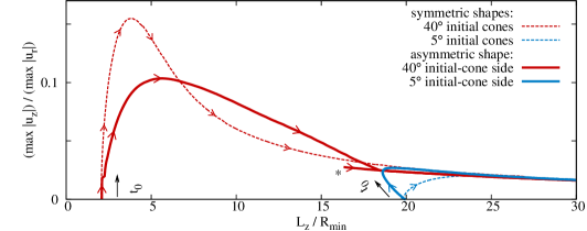
The shape and velocity field are interdependent, and it is informative to show how they co-evolve. Figure 7 condenses this information into a phase space. The vertical axis gives the ratio of the maximum surface vertical velocity component to the maximum surface radial velocity component (two distinct points). The horizontal axis gives the shape aspect ratio i.e., when the trajectory moves to the right, it corresponds to the neck shape becoming more long-and-slender. The top and bottom sides each have separate trajectories, and for comparison, we show each side’s symmetric counterpart (which shows what would happen if no flow were allowed through the plane Each trajectory starts on the horizontal axis, corresponding to the prescribed zero initial vertical velocity, at a position depending on the initial shape. For example, the initialised side begins with a corresponding aspect ratio of After an initial transient, all the curves coalesce onto a universal curve (Herbst & Zhang, 2011) and slowly progress to the universal form: long-and-slender (large shape aspect ratio) and radial flow (zero vertical velocity). The progression along the universal curve has been studied. We focus here on the transient.
Each side of the asymmetric shape differs significantly from its symmetric counterpart, indicating that the vertical flow through the mid-plane (interaction between the top and bottom) is important. The flow through the mid-plane allows the neck to shift until the straining flow is symmetric. The result is that the trajectories of the top and bottom sides “attract” one another in phase space. In this case, the direction of the neck shift is downward. The downward flow of the neck shift opposes the straining flow on the -initial top side, and augments the straining flow on the -initial bottom side. The result is that the peak surface vertical velocity ratio undershoots its symmetric counterpart on the top side (figure 7 top solid vs. dashed), whereas it overshoots its symmetric counterpart on the bottom side (figure 7 bottom solid vs. dashed). Similarly, the squat top side shape becomes more slender and the slender bottom side becomes more squat. In this way, the two trajectories are brought together in a short time. Some important features seen in previous plots can also be seen in figure 7. The local maximum vertical velocity (’*’ in figure 6) is shown as a separate trajectory in figure 7 (also indicated by ’*’). Also, figure 7 shows that the bottom side does not have to detour much in order to meet up with the top side trajectory. This effect was also seen in figure 3. In short, since the neck shifts down in this case, the singularity mostly inherits the characteristics of the bottom side. It is the top side that adjusts to mirror the bottom side, and the singularity ignores the fact that the top was initially squat. This effect can be reversed, as seen in the next section.
Tunable cone angle
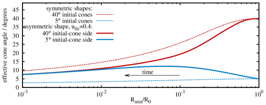
To understand the context for this section, refer back to figure 3. There, after a short transient, the top and bottom sides (solid lines) converge to a single trajectory that closely follows the trajectory of a –symmetric initial shape (lower dashed line). Here, by adding a vertical velocity to the initial conditions (equation 7 with non-zero ), the picture changes. A prescribed initial vertical velocity 40% in strength to the initial radial velocity, causes the shape to evolve into a symmetric shape that more closely follows the top-side –symmetric initial trajectory (figure 8, compare to figure 3). The added vertical velocity opposes the tendency for the neck to shift down in the early evolution. As a result, when the neck becomes symmetric, it inherits the characteristics of the top side, rather than the bottom side. This modest change in initial condition causes a qualitatively different outcome.
The effect is not bimodal, but continuous (see figure 9). For between the range of about to the resulting trajectory smoothly varies between the bottom-side dynamics and the top-side dynamics. For initial downward flow the system is insensitive to the exact value; any downward velocity just results in the singularity inheriting the bottom-side dynamics (there is no overshoot effect). Interestingly, the dynamics never fully approach the top-side trajectory, but seem to asymptote slightly below it. We do not have an explanation for this disparity.
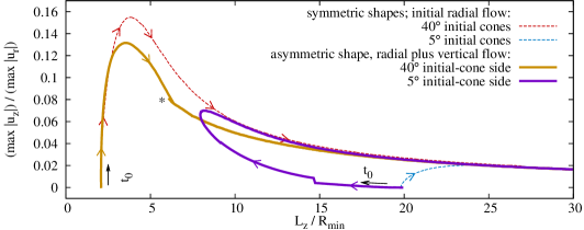
With an added vertical velocity it is the top side trajectory that dictates the evolution, with the bottom side going out of its way to accommodate (figure 10). The point on the phase diagram where the two trajectories merge (becoming symmetric) is shifted to the left and up, corresponding to a more squat aspect ratio with larger straining flow. Without the downward neck shift, the top side evolves almost as if it does not see the bottom (figure 10, similarity between top solid and top dashed). The initial vertical flow keeps the neck position elevated, and the singularity develops within the context of the top side. The resulting singularity inherits its characteristics from the top side, nearly ignoring the bottom side completely. A small initial vertical velocity near the neck can change whether the singularity inherits from the top side, the bottom side, or a blend of each.
5 Conclusion
In general, bubble pinch-off begins with some up–down asymmetry. We found that the neck adjusts the vertical position of the pinch-off point to make the neck shape and velocity field symmetric. If the initial flow field around the neck is purely radial, then the neck shifts (down) towards the more slender cone. The new neck forms with a top that emulates the bottom. The resulting singularity depends only on the initial The situation is reversed if a strong upward velocity is introduced to the neck during the creation stage. Then, the vertical flow prevents the neck from descending, and the new neck depends only on For intermediate upward velocities, the shape inherits a blend of the two angles.
If the singularity were allowed to proceed all the way to this effect would not matter since all symmetric necks, even squat ones, progress to a cylinder eventually (Herbst & Zhang, 2011). In reality, however, the asymptotic form progresses so slowly that other dynamics pre-empt the singularity before the neck can become slender. Therefore, it is the post-transient shape that sets up the post-pinch-off effects. For example, we expect that tuning the post-transient cone angle will play a significant role in the later effects, including neck air flow, azimuthal vibrations, and the Worthington jet, but more research is needed.
This work was supported by NSF No. CBET-0967282 and the Keck initiative for ultra-fast imaging (University of Chicago). The author thanks Justin Burton, Michelle Driscoll, Nathan Keim, Lipeng Lai, Sidney Nagel, Thomas Witten, and Wendy Zhang for discussions and suggestions.
References
- Bergmann et al. (2006) Bergmann, R., van der Meer, D., Stijnman, M., Sandtke, M., Prosperetti, A. & Lohse, D. 2006 Giant bubble pinch-off. Phys. Rev. Lett. 96, 154505.
- Burton & Taborek (2008) Burton, J. C. & Taborek, P. 2008 Bifurcation from bubble to droplet behavior in inviscid pinch-off. Phys. Rev. Lett. 101, 214502.
- Eggers et al. (2007) Eggers, J., Fontelos, M. A., Leppinen, D. & Snoeijer, J. H. 2007 Theory of the collapsing axisymmetric cavity. Phys. Rev. Lett. 98, 094502.
- Enríquez et al. (2011) Enríquez, O. R., Peters, I. R., Gekle, S., Schmidt, L. E., van der Meer, D. & Lohse, D. 2011 Non-axisymmetric impact creates pineapple-shaped cavity. Phys. Fluids 23 (9), 091106.
- Ferrante & Elghobashi (2004) Ferrante, A. & Elghobashi, S. 2004 On the physical mechanisms of drag reduction in a spatially developing turbulent boundary layer laden with microbubbles. J. Fluid Mech. 503 (3), 345–355.
- Frizell & Arndt (1987) Frizell, K. W. & Arndt, R. E. 1987 Noise generation by air bubbles in water: an experimental study of creation and splitting. Tech. Rep.. DTIC Document.
- Gekle & Gordillo (2010) Gekle, S. & Gordillo, J. M. 2010 Generation and breakup of worthington jets after cavity collapse. part 1. jet formation. J. of Fluid Mech. 663, 293–330.
- Gekle et al. (2010) Gekle, S., Peters, I. R., Gordillo, J. M., van der Meer, D. & Lohse, D. 2010 Supersonic air flow due to solid-liquid impact. Phys. Rev. Lett. 104 (2), 024501.
- Gekle et al. (2009) Gekle, S., Snoeijer, J. H., Lohse, D. & van der Meer, D. 2009 Approach to universality in axisymmetric bubble pinch-off. Phys. Rev. E 80 (3), 036305.
- Gordillo & Fontelos (2007) Gordillo, J. M. & Fontelos, M. A. 2007 Satellites in the inviscid breakup of bubbles. Phys. Rev. Lett. 98 (14), 144503.
- Gordillo et al. (2005) Gordillo, J. M., Sevilla, A., Rodríguez-Rodríguez, J. & Martínez-Bazán, C. 2005 Axisymmetric bubble pinch-off at high reynolds numbers. Phys. Rev. Lett. 95 (19), 194501.
- Herbst & Zhang (2011) Herbst, D. C. & Zhang, W. W. 2011 Underwater bubble pinch-off: Transient stretching flow. Phys. Rev. E 84, 026313.
- Ikeda et al. (2009) Ikeda, C. M., Wilkerling, J. & Duncan, J. H. 2009 An experimental investigation of the implosion of cylindrical shell structures. Presented at D.F.D. To be published. In contact with authors.
- Kawabuchi et al. (2011) Kawabuchi, M., Kawakita, C., Mizokami, S., Higasa, S., Kodan, Y. & Takano, S. 2011 Cfd predictions of bubbly flow around an energy-saving ship with mitsubishi air lubrication system. Mitsubishi Heavy Industries Technical Review 48 (1).
- Keim (2011) Keim, N. C. 2011 Perturbed breakup of gas bubbles in water: Memory, gas flow, and coalescence. Phys. Rev. E 83, 056325.
- Keim et al. (2006) Keim, N. C., Møller, P., Zhang, W. W. & Nagel, S. R. 2006 Breakup of air bubbles in water: Memory and breakdown of cylindrical symmetry. Phys. Rev. Lett. 97 (14), 144503.
- Lai (2012) Lai, L. 2012 Curvature singularity in the asymmetric breakup of an underwater air bubble. Phys. Fluids 24 (10).
- Lasheras et al. (2002) Lasheras, J. C., Eastwood, C., Martínez-Bazán, C. & Montañés, J. L. 2002 A review of statistical models for the break-up of an immiscible fluid immersed into a fully developed turbulent flow. Int. J. Multiphase Flow 28 (2), 247–278.
- Longuet-Higgins et al. (1991) Longuet-Higgins, M. S., Kerman, B. R. & Lunde, K. 1991 The release of air bubbles from an underwater nozzle. J. Fluid Mech. 230, 365–390.
- McCormick & Bhattacharyya (1973) McCormick, M. E. & Bhattacharyya, R. 1973 Drag reduction of a submersible hull by electrolysis. Nav. Eng. J. 85 (2), 11–16.
- Oğuz & Prosperetti (1993) Oğuz, H. N. & Prosperetti, A. 1993 Dynamics of bubble growth and detachment from a needle. J. Fluid Mech. 257, 111–145.
- Plesset & Prosperetti (1977) Plesset, M. S. & Prosperetti, A. 1977 Bubble dynamics and cavitation. Ann. Rev. Fluid Mech. 9.
- Pozrikidis (1997) Pozrikidis, C. 1997 Introduction to theoretical and computational fluid dynamics. NY: Oxford Univ. Press.
- Schmidt et al. (2009) Schmidt, L. E., Keim, N. C., Zhang, W. W. & Nagel, S. R. 2009 Memory-encoding vibrations in a disconnecting air bubble. Nat. Phys. 5 (5), pp. 343–346.
- Shi et al. (1994) Shi, X. D., Brenner, M. P. & Nagel, S. R. 1994 A cascade of structure in a drop falling from a faucet. Science 265 (5169), pp. 219–222.
- Turitsyn et al. (2009) Turitsyn, K. S., Lai, L. & Zhang, W. W. 2009 Asymmetric disconnection of an underwater air bubble: Persistent neck vibrations evolve into a smooth contact. Phys. Rev. Lett. 103 (12), 124501.
- Worthington & Cole (1897) Worthington, A. M. & Cole, R. S. 1897 Impact with a liquid surface, studied by the aid of instantaneous photography. Phil. Trans. R. Soc. A 189, pp. 137–148.