Reshaping and capturing Leidenfrost drops with a magnet
Abstract
Liquid oxygen, which is paramagnetic, also undergoes Leidenfrost effect at room temperature. In this article, we first study the deformation of oxygen drops in a magnetic field and show that it can be described via an effective capillary length, which includes the magnetic force. In a second part, we describe how these ultra-mobile drops passing above a magnet significantly slow down and can even be trapped. The critical velocity below which a drop is captured is determined from the deformation induced by the field.
I Introduction
Liquid oxygen is known for its paramagnetic properties since the pioneering work of James Dewar, who first noticed that it is attracted by the poles of an electromagnet Dewar1927 . Moreover, because of its low boiling point (C at atmospheric pressure), an oxygen drop on a substrate at room temperature rapidly evaporates, forming a cushion of vapour on which it levitates, a phenomenon known as the Leidenfrost effect, that was reported for the first time in 1756 Leidenfrost1756 ; Gottfried1966 and that continues to inspire research nowadays Thoroddsen2012 ; Qu r 2013 . A Leidenfrost drop achieves a perfect non-wetting situation, where there is no contact between the liquid and its solid support. As a consequence, drops adopt a very rounded shape and they are extremely mobile. Despite these remarkable properties, liquid oxygen has been much less described than other magnetic fluids such as ferrofluids (colloidal suspension of ferromagnetic nanoparticles), which are liquid at room temperature and have a much higher magnetic susceptibility (roughly 100 times higher than liquid oxygen). Liquid oxygen has nonetheless been studied in the framework of magnetic compensation of gravity Catherall2003 ; Nikolayev2009 , surface instabilities Takeda1991 ; Catherall2003Instabilities , and pumping with magnetic field Youngquist2003 ; Boulware20102 . Density and surface tension of liquid oxygen at the boiling point (C) are and mN/m. Takeda et al. Takeda1991ST showed that remains constant under a uniform magnetic field up to T. In this article, we study how the shape and mobility of oxygen drops are influenced by a magnet, which allows us to control them in a non-intrusive way. In a first part, we study how the shape of an oxygen drop is modified in a magnetic field, and we relate in a second part this deformation to the slowing down and capture of mobile drops.
II Static shape of oxygen drops
Liquid oxygen is obtained by distillation of air using liquid nitrogen, which boils at C. A copper sheet of millimetric thickness is folded and welded to obtain a cone of about cm height and width. It is then filled with liquid nitrogen: the cone temperature quickly reaches C, that is, C below the boiling point of oxygen present in the air, which therefore liquefies on the external surface of the cone. Liquid oxygen drains along the copper and drips at the tip, where it is collected and directly used. Along with oxygen, other components of air presenting a condensed phase at this temperature might be present. Argon, which liquefies at C and solidifies at C, should represent in the liquid obtained at the surface of the cone. Water should be present as solid in typically the same proportion, and ice crystals are indeed observed, making the drop milky, and thus uniformly dark when backlighted (Fig. 1). Carbon dioxide is also solid at this temperature, but it only represents a proportion on the order of 1 ‰.

Without magnetic field, the shape of a levitating oxygen drop is dictated by a balance between gravity and capillarity. As seen in Figure 1a, a drop of radius smaller than the capillary length mm, is almost spherical except for a small region at the bottom, of typical size Maha1999 . Thanks to surface reflection, we observe the presence of the vapour film, of typical thickness m, between the drop and its support. A small cloud is visible around the drop resulting from the condensation of water vapour present in air. Large drops () are deformed by gravity and look like puddles (not shown here), whose thickness is fixed by a balance between gravity and capillarity: in the limit where , we can approximate the shape of this gravity-dominated puddle by a cylinder of volume , whose total energy is minimal for .
A first experiment consists of approaching a magnet below an oxygen drop such as the one in Figure 1a. We use a cylindrical neodymium magnet, cm in diameter and cm thick, generating a magnetic field T at the surface of the magnet (measured with a Hall effect teslameter) and decreasing on a length-scale similar to the size of the magnet. As seen in Figure 1b, the drop is flattened and looks like a puddle, as if the presence of the magnet had modified the capillary length of oxygen. Figure 1c shows the same set-up turned upside down, holding the drop against gravity. The shape of the drop is almost the same as before, suggesting that magnetic effects dominate gravity. The magnet exerts a force per unit volume Rosensweig :
| (1) |
where is the magnetic susceptibility of liquid oxygen ( at C), the magnetic permeability of vacuum and the modulus of the magnetic field. The quadratic dependence with the magnetic field comes from the interaction between the imposed field and the induced magnetization of liquid oxygen, proportional to . This conservative force derives from a magnetic energy per unit volume:
| (2) |
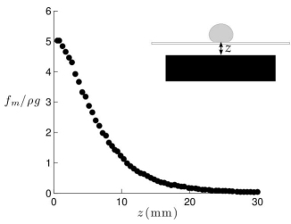
which is always negative for liquid oxygen and proportional to the square of the magnetic field, meaning that the drop is equally attracted by both poles of a magnet. In our experiment, the magnet is ten times larger than the drop. The magnetic field is therefore homogeneous in the horizontal plane and only depends on the vertical coordinate. We call the distance between the magnet and the bottom of the drop. The value of the magnetic force deduced from the measurement of above the magnet is reported in Figure 2.
Far from the magnet (mm), the magnetic force is negligible compared to the volumic weight . For mm, these two forces are on the same order, and the ratio can go up to five at a few millimeters from the magnet. This ratio can even be higher for smaller magnets, for which the magnetic field gradient is stronger. Since the magnetic force acts in the same direction as gravity, we define a modified capilllary length to account for the change of shape observed in Figure 1.
| (3) |
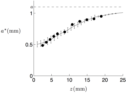
This modified capillary length reduces to the standard capillary length when is large, and it decreases as we get closer to the magnet. This explains the change of shape observed in Figure 1: placed at mm above the magnet where mm, a drop of radius mm is larger than and thus cannot remain spherical. If is initially larger than , the drop is flat and the presence of a magnetic field changes the thickness of the puddle, which is twice the capillary length. Measuring this thickness as a function of gives us a direct measurement of , that we can compare to the value obtained from equation (3), where is deduced from Figure 2. These results, shown in Figure 3, are in good agreement with each other. The capillary length can therefore be varied continuously by a factor two without changing the surface tension nor the density of the liquid.
The exact shape of a drop in the presence of a vertically varying magnetic field is determined by a balance between hydrostatic, magnetic and capillary pressures. This yields a differential equation for the drop profile, as detailed in the appendix. For the magnets that we used, the field decreases on a centimetric length-scale, which is much larger than the millimetric drop thickness. Therefore, the gradient of magnetic force is negligible at the scale of the drop, and shapes are those of puddles in a uniform enhanced gravitational field (Fig. 4). However, in the presence of a very large gradient of magnetic field, we could expect different shapes, with an enhanced curvature at the bottom. As discussed in the appendix, such shapes present similarities with what is observed in electrowetting on highly hydrophobic surfaces Mugele2007 . Note that we do not discuss here the shape of the interface below the drop, that may be deformed by the pressure in the vapour layer Nagel2012 . The vapour layer itself should be affected by the magnetic field, but the effect should be negligible: as recalled in Qu r 2013 , its thickness scales as where the length depends on the applied field, as for . But the field also increases the drop radius, as in the same limit. Hence the film thickness is independent of , when the field is strong, which qualitatively explains why we never saw any collapse of the Leidenfrost state, even in the limit .
III Capturing drops
Since there is no contact between liquid oxygen and its support, friction in the Leidenfrost state is almost inexistant: several meters are needed to observe the deceleration of a millimetric Leidenfrost drop thrown on a horizontal surface at a few tens of cm/s Dupeux2011 . Oxygen drops being sensitive to magnetic fields, it is natural to wonder whether and how magnetic traps can affect their mobility. To answer these questions, the following experiment is conducted: an oxygen drop of typical radius mm is thrown tangentially at a velocity on a horizontal square glass plate of side and thickness , under which is placed a parallelepipedic neodymium magnet (square cross-section of and length of cm), perpendicularly to the trajectory of the drop. Figure 5a is a spatio-temporal picture of such an experiment, seen from above, for which the drop arrives in the magnetic trap at a velocity cm/s.
We show in Figure 5b the oxygen velocity as a function of time during the experiment. It first weakly decreases far from the magnet. The corresponding deceleration can be extracted from the data slope between s and s (dashed line in Figure 5b). It is equal to cm/s2, so that the friction is of order N. Comparatively, the inertial friction in air is , on the order of 0.01 N to 0.1 N for between 20 cm/s and 60 cm/s. One also has to consider the viscous friction in the vapour layer, which is N (for a layer of thickness m, evaluated from close-up photographs taken with a stereo microscope). All together, this gives a friction force consistent with our measurement. As the drop gets closer to the magnet, it first accelerates to reach a velocity of about cm/s. The reduction of magnetic energy (eq. 2), which typically is for a drop in a field of magnitude , is on the order of the increase of kinetic energy per unit volume , yet higher since some magnetic energy is also transferred into deformation of the drop. The drop then decelerates as it leaves the magnetic trap, from which it comes out with a velocity cm/s, significantly below the velocity expected in the absence of a magnet. Passing across the trap thus produces on the whole a significant loss of kinetic energy, by a factor of order 3 in this example.
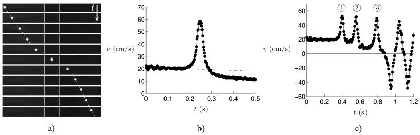
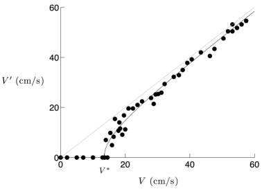
The same experiment can be done using a series of parallel magnets (fig. 5c). A certain amount of kinetic energy is lost above each magnet, and the drop gets captured when its inertia becomes weaker than the magnetic attraction. The drop is then trapped () and it oscillates several times above the magnet before viscosity and friction of air damp the motion. This experiment is repeated for various initial velocities between 1 and cm/s. Figure 6 summarizes the results, representing for each magnetic trap the exit velocity as a function of the entrance velocity . There is a critical velocity cm/s below which the drop is not able to escape (). Above this value, the difference decreases as increases, so that tends to zero for .
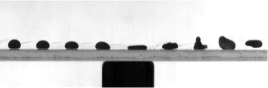
As it crosses the magnet (of centimeter-size), a drop loses a negligible amount of momentum () because of friction due to the surrounding air. The special dissipation in the trap rather seems to originate from the deformations in the field, which are not converted back into horizontal velocity when the drop leaves the magnet but relax into vibration modes Brunet2011 , which are eventually damped. This is obvious when looking at experiments from the side, as shown in Figure 7: the drop is flattened above the magnet and then it retracts to recover its rounded shape, which induces large vibrations and even lead in that case to a small jump, showing that the energy transferred into deformation can, at best, be converted into vertical kinetic energy.
We assume that the energy stored into deformation is lost, which yields a critical velocity for which the drop cannot escape , where is the mass of the drop. To evaluate , we look at the maximal radius achieved by the drop while crossing a magnet. We measure a ratio , which does not seem to depend on the drop velocity for between and cm/s. This value is similar to the one expected in a static situation: the numerical resolution of the shape (eq. A3) at mm above the same magnet gives . The deformation is thus equivalent when the drop crosses the magnet and when it is at rest in a similar magnetic field. Of course, if the time needed to deform the drop becomes larger than the time needed to cross the magnet (where is the size of the magnet), the drop does not have time to reach its maximal deformation. This would be the case for drops with a velocity m/s, a value that is never reached in our experiments.
The surface energy stored in deformation is , where is the increase in surface area of the drop. For the sake of simplicity, we restrict the discussion to spherical droplets, for which the variation of surface area is of order , where . For small deformations (), we obtain , which gives a critical velocity:
| (4) |
on the order of the measured value of . Above this threshold velocity, the drop is able to escape but loses a certain amount of kinetic energy which is always the same since does not depend on the velocity, in the range we explored. The terminal velocity can then be written:
| (5) |
This equation is plotted in Figure 6 with and it matches the measurements. It predicts in particular a critical behavior near and the asymptotic behavior () in the limit .
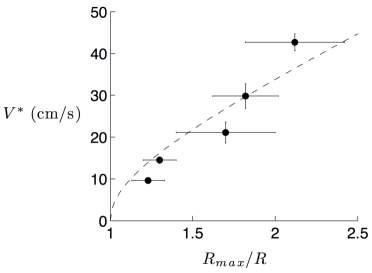
One way to test the scaling law (4) for is to vary by changing the distance between the magnet and the glass plate. We used five different distances , between and , and measured for each of them and . Deformation as high as were obtained, for which the critical velocity is approximately four times higher than before, as shown in Figure 8. Since , the approximation of small deformation is not valid anymore. In that regime, the general equation for the critical velocity becomes:
| (6) |
The dotted line in Figure 8 represents this equation where the velocity is treated as an adjustable parameter. The best fit is obtained for a value of , consistent with the expected order of magnitude, that is, .
Imposing a large deformation to the drop leads to a significant loss of kinetic energy. At an altitude mm above the magnet, the deformation is small and similar to the one observed in the static case. This is not true anymore for large deformations, as can be seen in Figure 9, showing a drop passing at above the magnet. We observe the formation of a rim, comparable to the shape of a bouncing drop Roisman2009 , which is clearly not expected in a static situation.
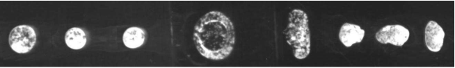
We measure a deformation much larger than the static value of mm given by the resolution of equation (A3) in the same field. The expansion takes place in approximately , which gives a characteristic internal velocity of . The energy of this flow is thus of order , that we can compare to the surface energy . Their ratio gives a Weber number of order unity for , and :
| (7) |
IV Conclusion
We described how drops of liquid oxygen can be deformed using a magnetic field. We characterized the magnetic force and showed that it can be several times higher than gravity and hence flatten the drop. This effect has been accounted for by the modification of the capillary length due to the magnetic force. We determined the equation for the shape of a drop in the presence of a vertically varying magnetic field and verified its validity by comparing the results to the observed shapes.
We also pointed out that these deformations can explain the strong deceleration of oxygen drops passing above a magnet. The surface energy stored in deformation is not recovered into kinetic energy, but rather converted into surface vibrations and internal motion, that are eventually damped. Hence, although the magnetic force is conservative, it can induce dissipation because of the deformability of the drop. We show that there is a critical velocity below which the drop is not able to escape from the magnetic trap. We proposed a scaling law that accounts for it. The magnets we used can rapidly impose large deformations to the liquid: we observed cases where a rim appears during the deformation, such as those observed with drops impacting a solid surface.
This simple system allows one to probe the dynamics of drops in a controlled way. We can imagine other experiments in the same vein using liquid oxygen or other magnetic fluids such as aqueous ferrofluids in the Leidenfrost state: imposing an oscillating magnetic field could be used for example to study the vibration modes of a droplet. A revolving field would permit the rotation (and subsequent deformation) of a liquid. Finally, this kind of control might be of high interest in application to aerospace engineering (where liquid oxygen is used as a propellant in combination with liquid hydrogen or kerosene), to control the position of liquid oxygen near the outlet of a rocket combustion chamber.
Appendix : calculation of the shape of a drop under magnetic field
The shape of a drop of liquid oxygen in a gradient of magnetic field can be calculated using the pressure balance on the drop. In order to simplify calculations, we place the origin at the upper pole of the drop, which is the starting point of the calculation, as shown in Figure A1. The vertical axis is oriented downwards. We consider the drop as axisymmetric and defined by a profile giving the radius of the drop at a given height .
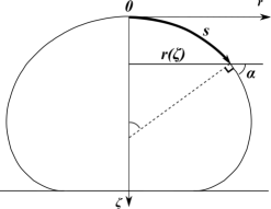
We call the curvilinear coordinate along and the angle between the surface and the horizontal. The pressure at a height is:
| (A1) |
The drop shape is given by balancing this pressure with the capillary pressure:
| (A2) |
where is the mean curvature of the surface at a height . For , we obtain , where is the curvature at the top of the drop. Combining equations (A1) and (A2) with the fact that derives from the magnetic energy (eq. 2), we obtain:
| (A3) |
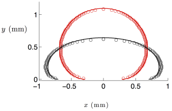
In order to compute the drop shape from this equation, we use the relationship , combined with and . Hence, we obtain a system of three differential equations for , and that we can solve numerically with appropriate boundary conditions (in particular, a contact angle of 180∘ at the solid contact) and compare to the measured profiles. The comparison is presented in Figure A2. The grey curve (red online, fig. A2a) represents the shape of a drop of radius mm in the absence of magnetic field (). Circles are measurements made from Figure 1a. We fit this shape using equation (A3), which fixes the value of . We then calculate the shape of a drop of same volume placed at an altitude mm above a magnet (fig. A2b). The value of used in the calculation comes from the measurement performed with the teslameter (fig. A2c).
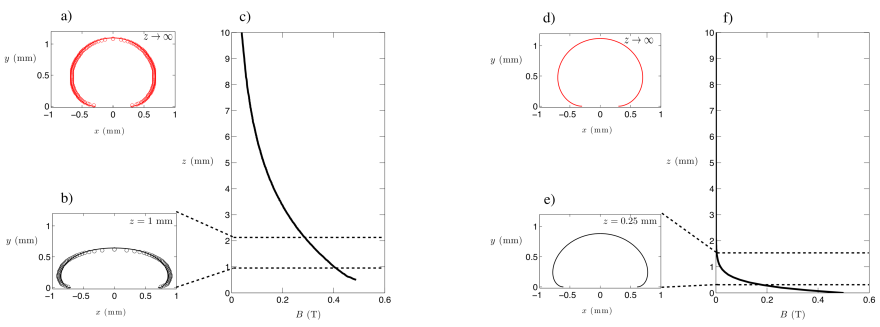
In the presence of a very large gradient of magnetic field, we could expect the magnetic force to be higher at the bottom of the drop than at the top, inducing an enhanced curvature at the bottom, as shown in Figure A2e. To compute this shape, we used a hypothetical field (where is expressed in mm and in T), which presents a strong variation on the drop scale (fig. A2f). Such a shape is clearly different from the puddles obtained under a uniform magnetic force, and it has similarities with shapes observed in electrowetting on highly hydrophobic surfaces, for which the connection between the local contact angle fixed by the Young–Laplace equation and the curvature imposed by the electric field similarly generates a strong curvature at the bottom Mugele2007 .
References
- [1] J. Dewar, Collected papers of Sir James Dewar (Cambridge University Press, Cambridge, 1927).
- [2] J. G. Leidenfrost De Aquae Communis Nonnullis Qualitatibus Tractatus (Duisburg, 1756).
- [3] B. S. Gottfried, C. J. Lee and K. J. Bell, “The Leidenfrost phenomenon: film boiling of liquid droplets on a flat plate,” Int. J. Heat Mass Transfer. 9, 1167 (1966).
- [4] I. U. Vakarelski, N. A. Patankar, J. O. Marston, D. Y. C. Chan and S. T. Thoroddsen, “Stabilization of Leidenfrost vapour layer by textured superhydrophobic surfaces,” Nature, 489, 274 (2012).
- [5] D. Quéré, “Leidenfrost Dynamics,” Annu. Rev. Fluid. Mech., 45, 197 (2013).
- [6] A. T. Catherall, L. Eaves, P. J. King and S. R. Booth, “Floating gold in cryogenic oxygen,” Nature 422, 579 (2003).
- [7] G. Pichavant, B. Cariteau, D. Chatain, V. Nikolayev, and D. Beysens, “Magnetic compensation of gravity: experiments with oxygen,” Microgravity Sci. Tech. 21, 129 (2009).
- [8] M. Takeda and K. Nishigaki, “Shape deformation of the gas-liquid interface of liquid oxygen in high-magnetic fields,” Phys. Rev. A 43, 2081 (1991).
- [9] A. T. Catherall, K. A. Benedict, P. J. King and L. Eaves, “Surface instabilities on liquid oxygen in an inhomogeneous magnetic field,” Phys. Rev. E 68, 037302 (2003).
- [10] R. C. Youngquist, “Dynamics of a finite liquid oxygen column in a pulsed magnetic field,” IEEE transactions on magnetics 39, 2068 (2003).
- [11] J. C. Boulware, H. Ban, S. Jensen and S. Wassom, “Experimental studies of the pressures generated by a liquid oxygen slug in a magnetic field,” J. Mag. Mag. Mat. 322, 1752 (2010).
- [12] M. Takeda and K. Nishigaki, “Measurement of the surface tension of liquid oxygen in high magnetic fields,” J. Phys. Soc. Japan 61, 3631 (1991).
- [13] L. Mahadevan and Y. Pomeau, “Rolling droplets,” Phys. Fluids 11, 2449 (1999).
- [14] R. E. Rowensweig Ferrohydrodynamics (Dover publications, Mineola, 1985).
- [15] F. Mugele and J. Buehrle, “Equilibrium drop surface profiles in electric fields,” J. Phys.: Condens. Matter 19, 375112 (2007).
- [16] J. C. Burton, A. L. Sharpe, R. C. A. van der Veen, A. Franco and S. R. Nagel, “Geometry of the vapor layer under a Leidenfrost drop,” Phys. Rev. Lett. 109, 074301 (2012).
- [17] G. Dupeux, M. Le Merrer, C. Clanet and D. Quéré, “Trapping Leidenfrost drops with crenelations,” Phys. Rev. Lett. 107, 114503 (2011).
- [18] P. Brunet and J. H. Snoeijer, “Star-drops formed by periodic excitation and on an air cushion - A short review”, E. Phys. J. Special Topics, 192, 207 (2011).
- [19] I. V. Roisman, E. Berberovic and C. Tropea, “Inertia dominated drop collision,” Phys. Fluids 21, 052103 (2009).