Further author information: (Send correspondence to A.S.)
A.S.: E-mail: atsushi.shimono@ipmu.jp, Telephone: +81 4 7136 5976
The system software development for prime focus spectrograph on Subaru Telescope
Abstract
The Prime Focus Spectrograph (PFS) is a wide field multi-fiber spectrograph using the prime focus of the Subaru telescope, which is capable of observing up to 2400 astronomical objects simultaneously.
The instrument control software will manage the observation procedure communicating with subsystems such as the fiber positioner ”COBRA”, the metrology camera system, and the spectrograph and camera systems. Before an exposure starts, the instrument control system needs to access to a database where target lists provided by observers are stored in advance, and accurately position fibers onto astronomical targets as requested therein. This fiber positioning will be carried out interacting with the metrology system which measures the fiber positions. In parallel, the control system can issue a command to point the telescope to the target position and to rotate the instrument rotator. Finally the telescope pointing and the rotator angle will be checked by imaging bright stars and checking their positions on the auto-guide and acquisition cameras. After the exposure finishes, the data are collected from the detector systems and are finalized as FITS files to archive with necessary information.
The observation preparation software is required, given target lists and a sequence of observation, to find optimal fiber allocations with maximizing the number of guide stars. To carry out these operations efficiently, the control system will be integrated seamlessly with a database system which will store information necessary for observation execution such as fiber configurations.
In this article, the conceptual system design of the observation preparation software and the instrument control software will be presented.
keywords:
control software, subaru, multi object spectrograph, survey1 INTRODUCTION
The Prime Focus Spectrograph (PFS [2012arXiv1206.0737E]) is a wide field multi-fiber spectrograph using the prime focus of the Subaru telescope, which is capable of observing up to 2400 astronomical objects simultaneously. Also the PFS is assumed to be used for large survey programs up to 300 nights in 5 years in total. The PFS system software is required to coordinate science observations and control entire instrument with interfacing control software of each component under environment conditions of Subaru telescope. For observations of survey programs, a number of targets observed at once is significantly large, capabilities for on-site automatical rearrangements and redesignings of survey programs are important for efficient survey operation. Since the PFS is planned to be an open use instrument of the Subaru telescope, the PFS system software and its architectural design is required to support both of survey programs and classical mode observation programs.
In this article, we will present requirements, system operational constraints, and conceptual design of the PFS system software.
2 Overview of PFS System Software
The PFS System software divides into three main deliverables (packages): the Observation Preparation Software, the Observation Execution Control Software, and the Engineering software.
The Observation Preparation Software will be used for the preparation of observations by astronomers at their local. This software package is required to perform: to divide large target lists into observations, generate the fiber and COBRA assignment as data files with matching targets to fibers with suitable guide star assignments, and generate observation sequence scripts for Subaru Observation System (Gen2) in a suitable format.
The Observation Execution Control Software will run at the Subaru observatory to control, configure and manage the entire PFS subsystem control software by communicating with and receiving commands from Gen2. For survey observation program, to achieve better survey performance, this software package will be required to work in cooperation with the data reduction pipeline and the observation preparation software.
The Engineering software is used for test, maintenance and calibration. This package provides engineering software per each subsystem which can work only with the local system, and simulator for each connection and interaction point for simulating missing subsystems during development and maintenance.
2.1 Relation among system software packages
To make three packages easily in cooperation, we will have one Relational Data Base Management System (RDBMS) database shared among packages. Every instrument configuration parameters and observation sequence information will be stored and shared in this database.
The engineering software package will be used independently with the Subaru telescope control system (TCS) and be used for local test, maintenance, and calibration. These results and calibrated parameters will be stored into the shared database and be used from other software packages. The observation preparation software will be used by astronomers to make an operation sequence for each observation program which will be supplied to the observation execution control software package via the shared database.
The observation execution control software package will control entire PFS sub-systems to perform science or engineering observations with referring information in the shared database supplied by other packages. For survey programs, the observation execution control software will communicate with the on-site quick-look data reduction system and the observation preparation software just after each exposure to update observation sequences of survey program considering quality assurance on observed data.
2.2 Relation to the Subaru
Among the entire PFS system software packages, mainly the observation execution control software will be required to communicate and cooperate with the Subaru telescope control software.
This package must run within environments of the Subaru observatory under three constraints, 1) this package must well communicate with the Subaru TCS and Gen2, 2) this package must send the Acquisition and Guide correction information to the Subaru TCS via a communication link specified by the Subaru observatory, 3) this package must perform operations under the operational conditions by the software environment of the Subaru telescope and the Gen2, as summarized in Figure. 1.

The observation execution software package (or the observation preparation software package) will create and supply observation sequence files named as skeleton or operational file. These sequence files will be executed by the Gen2 during the observation run with interfacing the other telescope control software and the PFS observation execution control software package (generally called as OBCP in the Subaru telescope) using three communication channels: 1) A command channel from Gen2 to OBCP, used by Gen2 to execute commands or query status. Every single command of OBCP and subsystems should be executable from Gen2. 2) A command channel from OBCP to Gen2 for querying OCS status, used by OBCP to query status from Gen2 with their name. 3) A data channel from OBCP to Gen2, used by OBCP to transfer observed data from each exposure in the format required by the Subaru observatory. Gen2 will send the received data into the Subaru Telescope data ARchive System (STARS).
2.3 Relation to subsystem control software
Every PFS subsystems supply their control software, the observation execution control software package will interface with these sub-system control software by three communication channels: 1) A command channel from the observation execution control software to subsystems to configure subsystems and execute commands 2) A status and log channel from subsystems to the observation execution control software to archive system statuses and logs of subsystems 3) A data channel from subsystems to the observation execution control software to transfer observed data by detectors’ control software. Examples of these communication channels are shown in Figure. 1.
3 System Architectural design
3.1 Activities taken by software packages
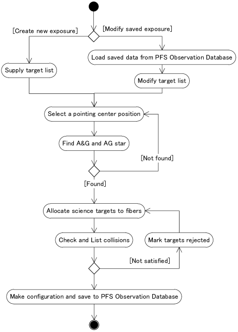
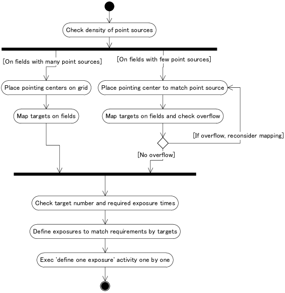
Activities performed by the observation preparation software are mainly to prepare a single observation (Figure. 2) and to prepare observation programs for entire survey programs (Figure. 3). The former activity will perform to define and update any required information for a single observation by the observation execution control software from a supplied list of targets by an astronomer. Since possible areas and brightness of objects used for Acquisition and Guidance (A&G) are limited in corresponding to a pointing center position of the instrument, the software need to check existence of suitable objects for A&G consulting with guide star catalogs. When the software could not find suitable objects more than required number, a user will be warned and be noticed to find another possible pointing center position by using the software. Once the pointing center position is confirmed, the software will try to allocate supplied science and calibration targets to fibers, considering distortion by the wide field collector (WFC) and collision among positioners. The latter activity uses the former one, and will be used to divide supplied target lists for survey programs into series of single observations considering target spatial density, required signal to noise ratio per target, and so on. This activity will also be used at the observatory during survey observations to update observation sequences by considering results from quick-look data reduction.
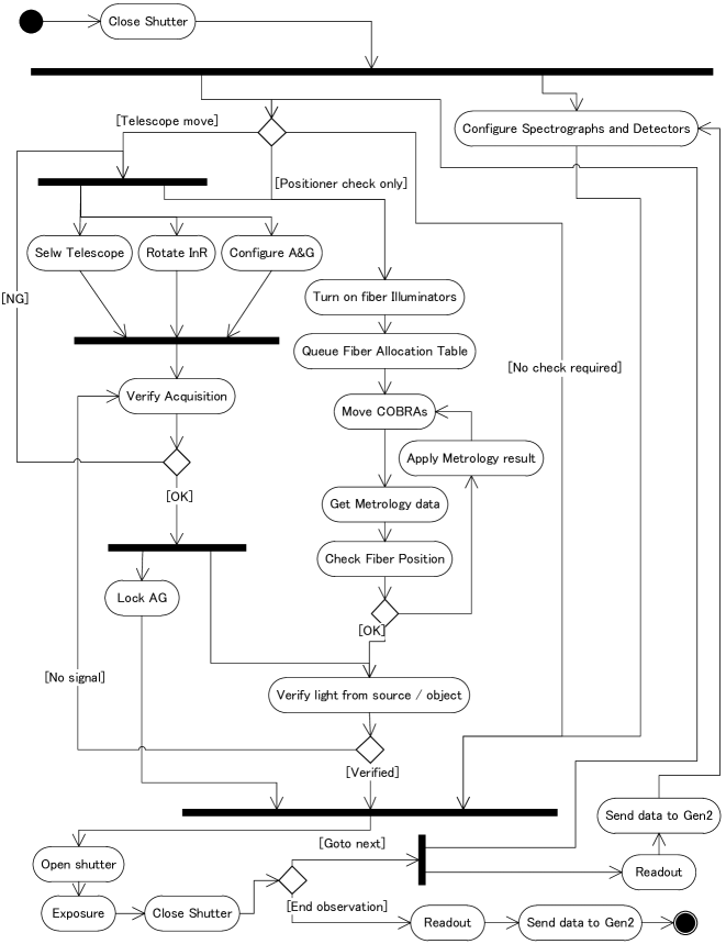
The observation execution control software will perform every activity required for observations as shown in Figure. 4 and also every user interface, including: providing integrated graphical user interfaces to command and check the fiber systems including the back illuminator; sequencing the Metrology process until science and calibration targets have been successfully acquired, and target exposures; completing the data acquisition by assembling required FITS header, and interfaces with the data handling system of Gen2; reporting errors and arises alarms of the entire instrument including the subsystems in the required way; creating observation and system logs including system statuses received from subsystems; and providing logging systems which enable operators and engineers to access, handle, and search easily even while offline.
To make survey observations more effectively and overhead more smaller, activities for target acquisition including telescope pointing and metrology procedure on positioners, and activities for finalizing data into the FITS format and configuration of spectrographs will be performed in parallel.
3.2 Shared database
To share configuration parameters for the instrument itself and observations, we will share one RDBMS database among every software components. Also we will use the Extensible Markup Language (XML) format to store and exchange its data for the observation preparation software working at astronomers’ site.
For survey programs, updating observation parameters including list of targets for upcoming exposures and their order depending observation conditions and observed data qualities is planned. To perform these on-site, we need to share information of targets and their observed data quality between the observation preparation software and the on-site quick-look data reduction pipeline. For this purpose, we will have another on-site database to store list of survey targets with required and observed data quality per each survey programs, including a copy of parameters used for executed observation.
3.3 Messaging hub, status and message log service
For communication between the PFS system software and every subsystem control software, we will select and use one network messaging library. Also, we are planning to have a log service both for message over network and for instrument status smoothly integrated to the network messaging library.
3.4 Error detection and handling
To have one central log service both for message exchanged over network and for instrument status with secure timestamps enables us to view and check those integrated log over entire instrument both on-line and off-line, and also to have another service independent from instrument control system to alert operators when any instrument status goes wrong or a continuous error detected for messages.
4 DISCUSSION
For on-site data storage used for survey observations, we considered two way; 1) totally integrated database system for all required information including observation configuration, target objects, and their achieved data quality from on-site data reduction pipeline, 2) separated database system for observation configuration and for list of target objects and their achieved data quality by each survey program. Since the PFS is supposed to be delivered to the Subaru telescope as a future facility instrument, we need to consider both of our proposing survey programs and also PI typed observation programs including small survey programs called as an intensive observation. Taking former option makes system software package more complex when we consider to ensure secure separation among observation programs, and also makes operational costs and risks on switching modes larger. Therefore we would take having a somewhat independent software suite including database system for survey programs.