Theory of strain controlled magnetotransport and stabilization of the ferromagnetic insulating phase in manganite thin films
Abstract
We show that applying strain on half-doped manganites makes it possible to tune the system to the proximity of a metal-insulator transition, and thereby generate a colossal magnetoresistance (CMR) response. This phase competition not only allows control of CMR in ferromagnetic metallic manganites but can be used to generate CMR response in otherwise robust insulators at half doping. Further, from our realistic microscopic model of strain and magneto-transport calculations within the Kubo formalism, we demonstrate a striking result of strain engineering that under tensile strain a ferromagnetic charge ordered insulator, previously inaccessible to experiments, becomes stable.
Introduction.—Transition metal oxides have long been studied for their surprising emergent behavior such as high superconductivity in the cuprates, ferroelectricity in the titanates, and colossal magnetoresistance (CMR) in the manganites. However, very recent advances in heterojunction growth Mannhart et al. (2010); Dagotto (2007); Hwang et al. (2012) have opened the possibility of producing atomically perfect interfaces of oxide materials, and therefore applying precisely controlled strain to oxide thin films. In this Letter we address the impacts of strain on ordered phases, temperature scales, and CMR in the manganites. As a specific example, we consider materials at “half-doping” which have a prototypical chemical formula of A0.5A’0.5MnO3 where A is a rare earth and A’ an alkaline earth metal Akahoshi et al. (2003).
At large bandwidths (BW), the half-doped manganites are ferromagnetic metals (F-M), while narrow BW materials are spin, charge, and orbitally ordered insulators (SCO-I) as described later in the text. CMR is known to occur in F-M materials close to the metal-insulator phase boundary, and is the result of phase competition (between the F-M and a charge-ordered insulator), which is traditionally controlled by isovalent chemical substitutions at the A-site Akahoshi et al. (2003). The unstrained material has been theoretically studied extensively Şen et al. (2010, 2007). Most prior work on the effects of strain (both theory Ahn et al. (2004); Baena et al. (2011); Dong et al. (2010); Lee et al. (2010); Ahn et al. (2001); Millis et al. (1998); Calderón et al. (2003) and experiment Yang et al. (2010); Okuyama et al. (2009); Wang et al. (2010); Chou et al. (2006); Xie et al. (2008); Pena et al. (2006); de Brion et al. (2004); Yang et al. (2006); Konishi et al. (1999)) have focused on how it affects the magnetic and electronic phases, with little emphasis on magnetotransport. We extend the usual model for manganites, previously used to study magnetotransport without strain Şen et al. (2010, 2007); Yu et al. (2008), to propose and solve, for the first time, a microscopic Hamiltonian that includes the effects of strain and obtain the following results:
(i) Tensile strain provides a route to stabilizing a ferromagnetic charge ordered insulator (FC-I). This phase has not been conclusively observed in any half doped manganite with tolerance factor variations, but should finally be observable with strain engineering.
(ii) We demonstrate that strain can induce phase transitions. As a consequence, we show that the CMR in F-M materials can be enhanced by tuning the proximity to the metal-insulator transition, and that insulating phases can be made metallic under strain and therefore also exhibit a CMR response. This greatly expands the family of materials with potential device applications.
(iii) We show that strain engineering also allows for control over in F-M manganites, and can be used to control the CMR temperature in the CMR materials.
Model.—We begin with the “standard model” for the manganites. Because of the octahedral crystal field, the Mn levels have a higher energy than the levels. Combined with a large Hund’s coupling, which ensures that the electron spins align ferromagnetically, this localizes three Mn electrons in the levels which form local moments (called “core spins”). The remaining electrons, if any, are itinerant and occupy two bands that result from the hybridization of the Mn levels. The model also includes an effective antiferromagnetic superexchange between neighboring Mn core spins, and finally the electrons couple to Jahn-Teller phonons with a coupling strength .
All energy scales are given in units of the unstrained bandwidth . This Hamiltonian yields an accurate description of the physics of the manganites Dagotto et al. (2001) and is discussed in detail in the Supplementary Information section I.
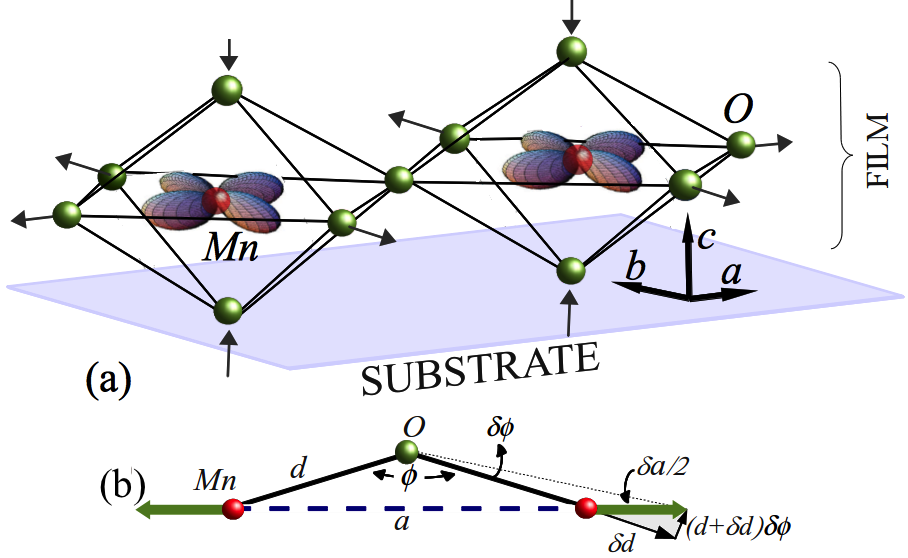
We extend this model to incorporate the effects of strain. Fig. 1(a) schematically illustrates substrate-induced, in-plane tensile strain. Tensile (compressive) strain is caused by growing the film on substrates with lattice parameters larger (smaller) than those of the unstrained film. We assume that strain is applied parallel to the (a-b) plane, which we take to be the plane of the orbital. We quantify strain by the parameter , where and are the substrate and film lattice parameters. Here is the distance between two nearest neighbor Mn atoms. We consider volume conserving strain and use the relation where is the Poisson ratio. We choose , consistent with previous estimates Yamada et al. (2006); Adamo et al. (2009). In-plane compressive strain corresponds to , while for tensile strain. With this in mind, we propose three microscopic effects of strain that must be included in our model, extending previous theoretical proposals Baena et al. (2011); Dong et al. (2010):
(i) Strain modifies the hopping matrix elements. Strain affects the lattice parameter which in turn modifies both the Mn-O bond length and the Mn-O-Mn bond angle as seen in Fig. 1(b). In the Supplementary Information section I (c), we show by using Slater-Koster Slater and Koster (1954) and Harrison Harrison (1989) scaling, that the effect on the hopping matrix elements due to the change in can be neglected for a large class of half doped manganites, and that the hopping in the (a-b) plane scales with strain as . We restrict our calculations to a single layer manganite film in the a-b plane (as depicted in Fig. 1(a)) and refer to the unstrained in-plane hopping parameter as , and under strain as .
(ii) Strain modifies the antiferromagnetic superexchange. The superexchange coupling also scales with the hopping. From similar considerations it can be shown that the in-plane superexchange scales as with strain. We refer to the unstrained in-plane superexchange as and in the strained case, .
(iii) Strain generates an orbital bias. Because of the increase in the in-plane Mn-O bond length, tensile strain makes occupation of the orbital energetically favorable. In-plane compressive strain favors the out-of-plane orbital. This orbital bias induced by in-plane compressive and tensile strains in La0.7Sr0.3MnO3 has been observed in x-ray absorption Aruta et al. (2006) as well as in angle resolved photoemission Tebano et al. (2010). We incorporate this in our model Hamiltonian with an extra term, where for and for .
From experiments, the splitting has been estimated to be between and Aruta et al. (2006); Tebano et al. (2006). We make a conservative estimate for the bias to be , i.e., a splitting of for 2 strain. These values are consistent with density functional estimates Nanda et al. (2008, 2010). Values of 2-3 for strain on manganite films, as we consider here, are easily achievable in experimentsOkuyama et al. (2009); Yang et al. (2006).
As mentioned, we perform our calculations in two dimensions, describing a single-layer manganite film in the a-b plane. Further, we assume strain to be uniform in the layer. This is sufficient to bring out the important features of the phase diagram and in-plane transport. We describe our method of solution in Supplementary Information sections II and III and focus here on our results.
Strain driven phase transitions.—Fig. 2(b) shows the phase diagram without strain. On this we denote two representative parameter points, F-M (blue dot) and SCO-I (red dot). The SCO-I is an insulator with planar checkerboard charge order (CO), alternating orbital order (OO) (on the sites with larger charge density), and CE type spin order (zig-zag ferromagnetic chains coupled antiferromagnetically). Fig. 2(a) and (c) show the effect of strain on these points.
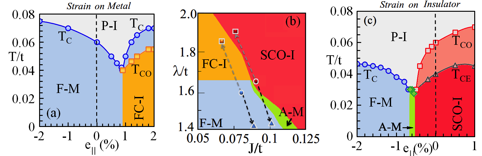
Starting from these parameters, in-plane compressive strain favors F-M as seen in both (a) and (c). There are two competing effects here, however. Compressive strain increases the in-plane hopping which in turn reduces , as seen by following the dashed black arrow in (b). This favors a metallic state where double-exchange promotes ferromagnetism. On the other hand, compressive strain increases , which tends to narrow the BW, while the orbital bias promotes occupancy of the out-of-plane orbital. Both of these latter effects work against the stability of the F-M, but we find the F-M to be dominant up to the maximum values of strain we have considered.
In-plane tensile strain stabilizes insulators that can have either ferromagnetic or antiferromagnetic spin textures as seen in (a) and (c) respectively. The insulators have long-range checkerboard charge order and are stabilized by the reduced in-plane hybridization or increased , as seen by following the grey dashed arrow in (b). This effect tends to localize the electrons. While sufficient increase in eventually turns the system insulating regardless of the unstrained F-M parameter, the magnetic order depends crucially on the value of .
This dependence of the magnetic/charge-ordering scales on strain has been seen in experiments, both away from Chou et al. (2006) and at half-doping Yang et al. (2006); Okuyama et al. (2009). They include increasing with compressive strain in a Ba0.2MnO3, suppressing with tensile strain in La0.67Ca0.33MnO3, and increasing with tensile strain on Pr0.5Ca0.5MnO3 Yang et al. (2006); Okuyama et al. (2009). We note that while there is a dearth of experimental data on scaling of t and J for manganites, our results are robust to typical variations in the scaling sca .
Stability of the FC-I phase.—From Fig. 2 (b) we see that adequate tensile strain on F-M with J/t0.05-0.08 convert the system into a FC-I, just as that depicted for (, ) by the grey dashed arrow. The unstrained FC-I phase, was predicted in theory Yunoki et al. (2000) at values as in Fig. 2 (b). In small BW half-doped manganites, e.g. La0.5Ca0.5MnO3, signatures of this phase coexisting with AF-CO phase were reported Loudon et al. (2002) at 90K. This implies that in the half-doped manganites either FC-I is the true ground state only in a narrow widow or it is a metastable state with energy very close to the true ground state. We predict that tensile strain on an ordered F-M suppresses other phases and can stabilize the FC-I as the ground state.
Effect of strain on magnetotransport.—The maximum CMR temperature achievable by BW tuned phase competition is the of the unstrained material. Additionally, bicritical nature of the phase diagram and proximity to the metal-insulator boundary needed for CMR, keeps the quite low Tokura (2000). We show that because strain affects different intrinsic energy scales differently, it not only tunes phase competition, but also allows optimization of the competition between CMR temperature and MR.
Fig. 3(a) shows the resistivity, , for various tensile strain values on the unstrained F-M phase (blue dot in Fig. 2(b)). While CMR behavior has been reported before Şen et al. (2010, 2007); Dong et al. (2010), our novelty is the use of strain as an external knob. Increasing tensile strain causes rapid rise in the resistivity maximum that occurs at , accompanied with reduction of both the and the temperature at the resistivity maximum (). The reduction in is due to the approach to the F-M/SCO-I boundary by increasing the tensile strain, as depicted in the inset in (a). The reason for the increase in the resistivity maximum is the strain-induced enhancement of metal-insulator coexistence at as illustrated in (b).
The color maps here depict the volume fraction of the insulating regions (red patches) embedded in an otherwise conducting background at . These insulating regions grow in volume with increasing strain and have short range () CO correlations; the same correlations that one finds in the competing FC-I phase. The thermal fluctuations at are typically dominated by the nearest metastable minimum, in this case the FC-I phase. Further, since strain controls the proximity to the F-M/FC-I boundary, increasing tensile strain makes the FC-I state progressively approach the energy of the F-M ground state, favoring greater insulating regions with short range () CO correlations. If we start with other initial (unstrained) starting points, tensile strain can result in a F-M to SCO-I phase transition. The qualitative behavior of magnetotransport is the same as in the F-M to FC-I case shown here. Magnetotransport data near the FM/SCO-I phase boundary is shown in Supplementary Information Section IV.
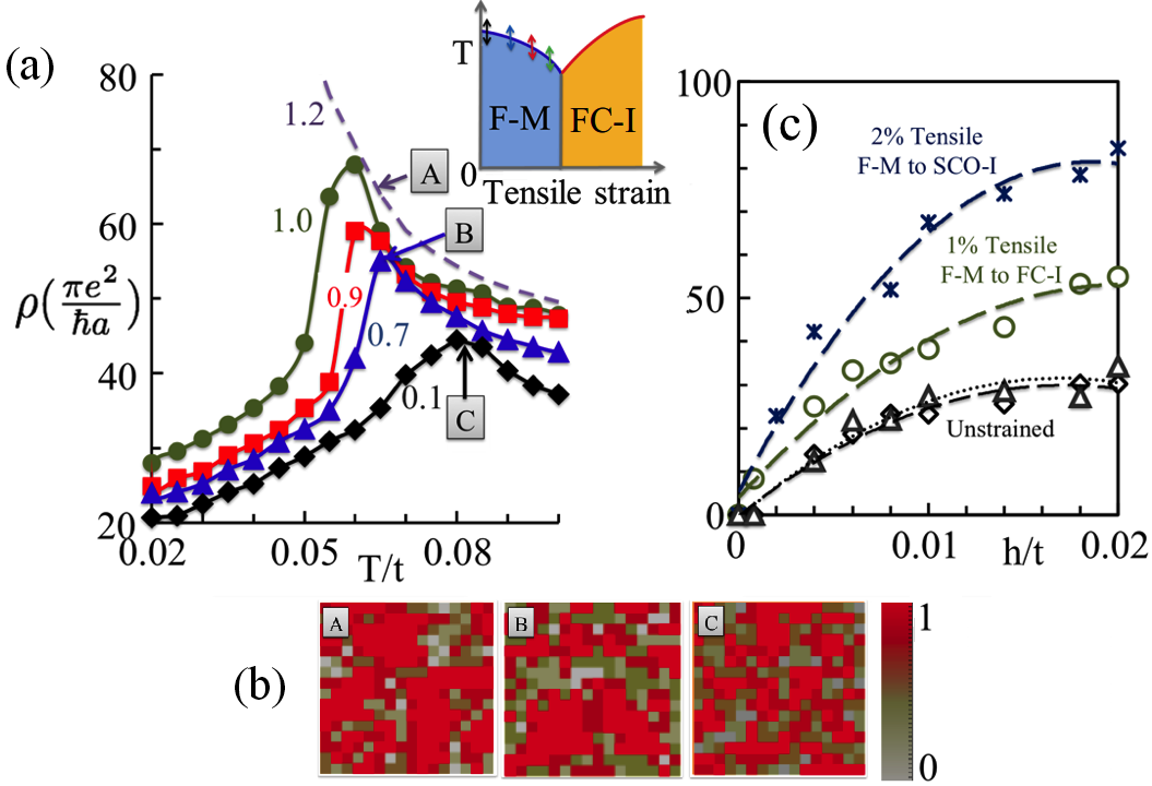
In Fig. 3(c) we show the , defined as and calculated at , as a function of magnetic field for two cases. One shows MR close to the F-M/FC-I phase boundary, with (circles) and without (diamonds) strain; the other shows MR close to the F-M/SCO-I boundary. The amount of increase in the resistivity maximum with strain and the depends on the domains of metastability of the competing phases, the type of the insulator and the largest tensile strain that can be applied before the system becomes insulating. However regardless of the nature of metal-insulator phase competition, applying tensile strain yields an enormous enhancement of MR (circles and stars) over the unstrained values (diamonds and triangles).
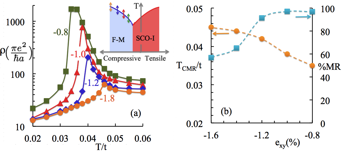
Finally we demonstrate that compressive strain can drive insulators across the metal-insulator transition into the CMR regime. Fig. 4(a) shows with increasing compressive strain on SCO-I. At 0.8 strain, the insulator-to-metal transition is accompanied by a CE-to-ferromagnetic transition. Increasing the compressive strain further causes a monotonic increase in (also seen in the inset in (a)). The peak in the resistivity with increasing strain is also systematically shifted to higher temperatures. In (b) we plot MR at the temperature of the resistivity maximum as a function of strain. We also show the corresponding CMR temperatures (). We find that is reduced upon increasing strain, as expected, but there is in fact an optimal region in which can be increased without substantially reducing . We have checked that our results survive A site disordering.
Conclusion.—We stress a major difference between the strain engineering and isovalent substitution. While both can tune the bandwidth, uniform strain will not introduce the short-range disorder that naturally results from substitution. As a result, ferromagnetic ’s and of strained films should be higher than in their substitution-engineered counterparts. In turn, larger intrinsic bandwidth would cause greater MR at smaller magnetic fields, since the external field required to align the core spins is reduced. Also, strain effects on manganites of any material composition and doping can be directly studied in our approach. Our results indicate some promising future directions. First, we have demonstrated that strain gives access to a large phase space of new and accessible states for a given unstrained material. Second, strain need not introduce disorder, in contrast to chemical substitution. Finally, strain directly impacts orbital occupancy in a tunable way, and opens new possibilities for orbital-state sensitive electronics.
We gratefully acknowledge support from DOE DE-FG02-07ER46423 (A.M.), DOE BES DE-SC0005035 (M.R.), NSF DMR-0907275 (N.T.), and Center for Emergent Materials, NSF MRSEC DMR-0820414 (W.S.C. and P.W.).
References
- Mannhart et al. (2010) J. Mannhart et al., Science 327, 1607 (2010).
- Dagotto (2007) E. Dagotto, Science 318, 1076 (2007).
- Hwang et al. (2012) H. Y. Hwang et al., Nature Materials 11, 103 (2012).
- Akahoshi et al. (2003) D. Akahoshi et al., Phys. Rev. Lett. 90, 177203 (2003).
- Şen et al. (2010) C. Şen et al., Phys. Rev. Lett. 105, 097203 (2010).
- Şen et al. (2007) C. Şen et al., Phys. Rev. Lett. 98, 127202 (2007).
- Ahn et al. (2004) K. H. Ahn et al., Nature 428, 401 (2004).
- Baena et al. (2011) A. Baena et al., Phys. Rev. B 83, 064424 (2011).
- Dong et al. (2010) S. Dong et al., Phys. Rev. B 82, 035118 (2010).
- Lee et al. (2010) J. H. Lee et al., Phys. Rev. Lett. 104, 207204 (2010).
- Ahn et al. (2001) K. H. Ahn et al., Physical Review B 64, 115103 (2001).
- Millis et al. (1998) A. J. Millis et al., Journal of Applied Physics 83, 1588 (1998).
- Calderón et al. (2003) M. J. Calderón et al., Physical Review B 68, 100401 (2003).
- Yang et al. (2010) F. Yang et al., Appl. Phys. Lett. 97, 092503 (2010).
- Okuyama et al. (2009) D. Okuyama et al., Appl. Phys. Lett. 95, 152502 (2009).
- Wang et al. (2010) J. Wang et al., Appl. Phys. Lett. 96, 052501 (2010).
- Chou et al. (2006) H. Chou et al., Appl. Phys. Lett. 89, 082511 (2006).
- Xie et al. (2008) C. K. Xie et al., Appl. Phys. Lett. 93, 182507 (2008).
- Pena et al. (2006) V. Pena, Z. Sefrioui, D. Arias, C. Leon, J. Santamaria, M. Varela, S. Pennycook, M. Garcia-Hernandez, and J. Martinez, Journal of Physics and Chemistry of Solids 67, 472 (2006).
- de Brion et al. (2004) S. de Brion, G. Chouteau, A. Janossy, E. R. Buzin, and W. Prellier, Journal of Magnetism and Magnetic Materials 272 - 276, Part 1, 450 (2004).
- Yang et al. (2006) Z. Q. Yang et al., Applied Physics Letters 88, 072507 (2006).
- Konishi et al. (1999) Y. Konishi et al., J. Phys. Soc. Jpn. 68, 3790 (1999).
- Yu et al. (2008) R. Yu et al., Phys. Rev. B 77, 214434 (2008).
- Dagotto et al. (2001) E. Dagotto et al., Physics Reports 344, 1 (2001).
- Yamada et al. (2006) H. Yamada et al., Appl. Phys. Lett. 89, 052506 (2006).
- Adamo et al. (2009) C. Adamo et al., Appl. Phys. Lett. 95, 112504 (2009).
- Slater and Koster (1954) J. C. Slater and G. F. Koster, Phys. Rev. 94, 1498 (1954).
- Harrison (1989) W. Harrison, Electronic Structure and the Properties of Solids: The Physics of the Chemical Bond, Dover (1989).
- Aruta et al. (2006) C. Aruta et al., Phys. Rev. B 73, 235121 (2006).
- Tebano et al. (2010) A. Tebano et al., Phys. Rev. B 82, 214407 (2010).
- Tebano et al. (2006) A. Tebano et al., Phys. Rev. B 74, 245116 (2006).
- Nanda et al. (2008) B. R. K. Nanda et al., Phys. Rev. B 78, 054427 (2008).
- Nanda et al. (2010) B. R. K. Nanda et al., Phys. Rev. B 81, 174423 (2010).
- Pradhan et al. (2007) K. Pradhan et al., Phys. Rev. Lett. 99, 147206 (2007).
- (35) At low temperatures () strain causes phase separation between F-M and SCO-I or FC-I, as seen in experiments Tebano et al. (2006); Pena et al. (2006); de Brion et al. (2004) and theory Ahn et al. (2004). However, with increasing temperature, such phase separated states rapidly evolve either into a global F-M or SCO-I phase and do not affect our finite temperature results. .
- (36) Using t and J known for La2CuO4 Cooper et al. (1990), only causes quantitative changes. It shifts the metal-insulator transition in Fig 2 (a) to 2 tensile strain and that in Fig 2 (b) to about 2.5 compressive strain. These changes are small enough so that our results are still easily accesible to experiments .
- Yunoki et al. (2000) S. Yunoki et al., Physical Review Letters 84, 3714 (2000).
- Loudon et al. (2002) J. C. Loudon et al., Nature 420, 797 (2002).
- Tokura (2000) Y. Tokura, Colossal Magnetoresistive Oxides, Gordon and Breach, Amsterdam (2000).
- Cooper et al. (1990) S. L. Cooper, G. A. Thomas, A. J. Millis, P. E. Sulewski, J. Orenstein, D. H. Rapkine, S.-W. Cheong, and P. L. Trevor, Phys. Rev. B 42, 10785 (1990).