Observation of linear-polarization-sensitivity in the microwave-radiation-induced magnetoresistance oscillations
Abstract
In the quasi two-dimensional GaAs/AlGaAs system, we investigate the effect of rotating in-situ the electric field of linearly polarized microwaves relative to the current, on the microwave-radiation-induced magneto-resistance oscillations. We find that the frequency and the phase of the photo-excited magneto-resistance oscillations are insensitive to the polarization. On the other hand, the amplitudes of the magnetoresistance oscillations are remarkably responsive to the relative orientation between the microwave antenna and the current-axis in the specimen. The results suggest a striking linear-polarization-sensitivity in the radiation-induced magnetoresistance oscillations.
pacs:
72.20.My, 72.20.Fr, 72.80.Ey, 73.43.FjI introduction
High quality quasi two-dimensional electron systems (2DES) realized in GaAs/AlGaAs semiconductor heterostructures have long served to examine intriguing phenomena.grid-2 ; grid-1 The rich new physics in this material system has animated further improvements in material quality which, in turn, has driven new developments within the field. Physical phenomena induced by microwave and terahertz photo-excitation at high filling factors or low magnetic fields, , may be counted amongst these developments. Here, the realization of radiation-induced -periodic magnetoresistance oscillations and associated zero-resistance states led to broad experimental grid1 ; grid2 ; grid3 ; grid4 ; grid5 ; grid6 ; grid7 ; grid8 ; grid9 ; grid11 ; grid12 ; grid13 ; grid15 ; grid16 ; grid17 ; grid19 ; grid20 ; grid21 ; grid22 and theoreticalgrid23 ; grid24 ; grid25 ; grid26 ; grid101 ; grid27 ; grid28 ; grid29 ; grid30 ; grid31 ; grid32 ; grid33 ; grid34 ; grid35 ; grid36 ; grid37 ; grid38 ; grid39 ; grid40 ; grid42 ; grid43 ; grid44 ; grid45 ; grid46 ; grid47 ; grid48 ; grid49 investigations of transport in the photo-excited 2DES.
The microwave and terahertz radiation-induced magneto-resistance oscillations in the 2DES are characterized by periodic oscillations in the diagonal magnetoresistance, , of the 2DES at cryogenic temperatures, . These oscillations show a strong sensitivity to and the microwave power, , at modest . Proposed mechanisms for such oscillations include radiation-assisted indirect inter-Landau-level scattering by phonons and impurities (the displacement model),grid23 ; grid25 ; grid27 ; grid46 non-parabolicity effects in an ac-driven system (the non-parabolicity model),grid101 a radiation-induced steady state non-equilibrium distribution (the inelastic model),grid33 and the periodic motion of the electron orbit centers under irradiation (the radiation driven electron orbit model).grid34 ; grid37
Under typical experimental conditions, some or all of these mechanisms can contribute towards sufficiently large amplitude radiation-induced magneto-resistivity oscillations such that, theoretically, at the oscillatory minima, the magneto-resistivity is able to take on negative values. According to theory, negative resistivity triggers, however, an instability in the uniform current distribution, leading to current domain formation, and the experimentally observed zero-resistance states.grid24 ; grid43
Although these theories suggest radiation-induced magneto-resistance oscillations, they differ with respect to their predictions on, for example, the microwave polarization sensitivity in the radiation-induced oscillations. Here, the displacement model predicts that the oscillation-amplitude depends on whether the microwave electric field, , is parallel or perpendicular to the -electric field, .grid25 On the other hand, the inelastic model unequivocally asserts polarization insensitivity to the radiation-induced magneto-resistance oscillations.grid33 Polarization immunity, in the radiation-driven electron orbit model, depends parametrically upon the damping factor, , exceeding the frequency of the microwave field.grid37 Finally, the non-parabolicity model suggests a perceptible polarization sensitivity for linearly polarized microwaves,grid101 while indicating the absence of such oscillations for circularly polarized radiation.grid101 From the experimental perspective, previous work on L-shaped Hall bars indicated that the frequency and phase of the radiation-induced magnetoresistance oscillations are insensitive to the microwave polarization.grid5 Other work on square-shaped specimens asserted the insensitivity of the microwave induced magneto-resistance oscillations to the polarization sense of circularly and linearly polarized microwaves.grid13

Here, we investigate the effect of rotating, in-situ, the polarization of linearly polarized microwaves relative to long-axis of Hall bars. Strikingly, we find that the amplitude of the radiation-induced magneto-resistance oscillations are remarkably responsive to the relative orientation between the linearly polarized microwave electric field and the current-axis in the specimen. The results appear qualitatively consistent with the displacement, the non-parabolicity, and the radiation driven electron orbit model for .
II Experiment and Results
Experimental microwave polarization studies in this context are difficult to carry out since it is non-trivial to rotate, in-situ, a specimen with wires over at the end of a long sample holder, within a small () diameter low temperature cryostat. To overcome this barrier, we have developed, instead, a setup where the wired sample remains fixed within the cryostat, while the microwave polarization is rotated with respect to the sample, from outside the cryostat. To achieve this capability, see Fig. 1, the canonical rectangular waveguide was replaced with a circular ( i.d.) waveguide, and a rotatable coax-to-waveguide-adapter, probe-coupled, electric-monopole-antenna, microwave-launcher [MW-antenna in Fig. 1(a)] was developed to couple microwaves into the waveguide. Here, the angular position of the MW-antenna could be set as desired and then locked in place with a clamped quick connect. The Hall bar sample was mounted at the low temperature () end of the circular waveguide as shown in Fig. 1(a), and the long axis of the device was oriented parallel to polarization axis of the MW-antenna. Thus, , [see Fig. 1(b)], represents the rotation angle of the MW-antenna with respect to the device long-axis. These Hall bars, with a width , were characterized by n (4.2K) = 2.2 and . The four-terminal diagonal resistance, , was extracted from measurements between adjacent diagonal voltage contacts, [see Fig. 1(b)], as the current was applied via the ends. Thus, the length (L)-to-width (W) ratio for the measurements was , see Fig. 1.
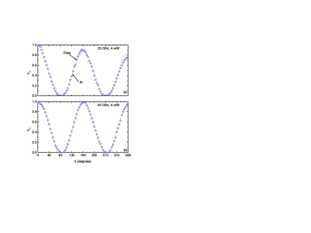
Some questions of interest here include whether polarized microwaves are produced by the MW antenna, and whether this polarization is preserved to the specimen. In order to answer these questions, preliminary tests were carried out using an ”analyzer” consisting of an electric-monopole, probe-coupled-antenna and square law detector. Bench tests carried out with the MW-antenna [Fig. 1(a)] and the ”analyzer” indicated that polarized microwaves were generated by the microwave launcher. For further tests, this ”analyzer” was placed at the sample end of the sample holder and fixed at a particular orientation, as the MW-antenna was rotated through at increments. Fig. 2(a) and 2(b) show the normalized detector response, , of the diode detector at and . The figure exhibits the expected sinusoidal variation, i.e., , for linearly polarized radiation, of the received power as a function . Also shown in Fig. 2 are fits to . We find, for Fig. 2(a), , , and , and for Fig. 2(b), , , and . Here, is within experimental uncertainties. Thus, polarized radiation is generated at the launcher and the polarization is preserved down to the sample.
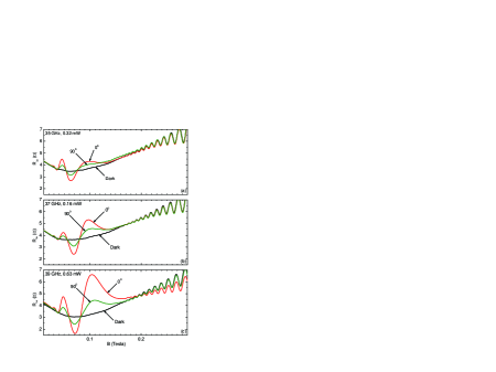
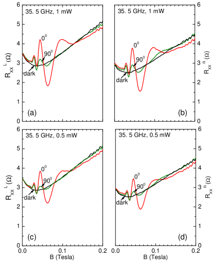
Figure 3 exhibits the vs. at , with the Hall bar sample () in place at the bottom of the waveguide sample holder. Figures 3(a) and (b) show the results obtained at a source-power , while Figs. 3(c) and(d) show the same obtained at . Here, and represent the measurement on the left (L) and right (R) sides of the device(Fig. 1). Each panel of Fig. 3 includes three traces: A dark trace (in black) obtained in the absence of microwave photoexcitation. A trace in red, where the MW antenna is parallel to the long-axis of the Hall bar. A comparison of Fig. 3(a) and (c) [or Fig. 3(b) and (d)] shows that the (red) traces exhibit larger-amplitude radiation-induced magneto-resistance oscillations at than at . This feature corresponds to the usual observation that the oscillation-amplitude increases with at modest photo-excitation.grid21 ; grid49 Finally, the panels of Fig. 3 also exhibit, in green, the traces, where the MW antenna is perpendicular to the long-axis of the Hall bar. Again, as expected, a comparison of Fig. 3(a) and (c) [or Fig. 3(b) and (d)] shows that the traces exhibit larger amplitude radiation-induced magneto-resistance oscillations at [Fig. 3(a)] than at [Fig. 3(b)].
The remarkable feature is observed when one compares the red () and green () traces within any single panel of Fig. 3. Such a comparison indicates that the amplitude of the radiation-induced magneto-resistance oscillations is reduced at the MW antenna orientation. Thus far, our experiments have shown upto a factor-of-ten reduction in the oscillation amplitude under polarization rotation. Although the magneto-resistance oscillations are reduced in amplitude, typically, they are not completely extinguished at . Finally, the period and the phase of the radiation-induced magnetoresistance oscillations are unchanged by MW-antenna rotation; this feature is readily apparent in Fig. 3. Figure 4 illustrates similar measurements in a second specimen () at [Fig. 4(a)], [Fig. 4(b)], and [Fig. 4(c)] at various . As is evident in Fig. 4, the oscillation amplitude is again reduced for .
III Discussion
In considering the implications, it is necessary to note that, since over the range of where the photo-excited resistance oscillations are observed, the -electric field should be oriented nearly perpendicular to the Hall bar axis (see Fig.1). In the displacement model of ref.grid25 , the inter-Landau level contribution to the photo-current includes a term with a Bessel function whose argument depended upon whether and are parallel or perpendicular to each other. Hence, the dissipative microwave photoconductivity can exhibit polarization selectivity in the displacement model. According to ref. grid33 , for , where and are the inelastic- and the single particle- relaxation times, respectively, a larger contribution to the amplitude of the radiation-induced magneto-oscillations is provided by the inelastic mechanism than by the displacement mechanism. Further, Ref. grid33 indicated that the inelastic mechanism does not depend on the orientation of the linear polarization of the microwave field, unlike the displacement mechanism, which also yields a -independent contribution to the oscillatory conductivity. In their radiation driven electron orbit model,grid37 polarization immunity is realized when . Finally, the non-parabolicity model included a strong polarization sensitivity, with the dissipation an odd function of the de-tuning from cyclotron resonance.grid101
Based on the above, these experimental results appear qualitatively similar to expectations based on a ”displacement” or ”non-parabolic” or a ”radiation-driven electron orbit” term with . Yet, the experimental feature that the oscillations do not vanish completely at seems not to rule out, at least at this stage of experimentation, the existence of a linear-polarization-immune-term in the radiation-induced transport. Next, we address the report of linear polarization immunity in Ref. grid13 . Those measurements were apparently carried out on square shaped specimens, with a length to width ratio of one.grid13 In such a square specimen with point contacts, the current stream lines are expected to point in different directions over the face of the sample. Then, the variable angle between the linear microwave polarization and the local current orientation could possibly serve to produce an effectively polarization averaged measurement.
Finally, we comment upon expectation for the relative sensitivity/immunity of the radiation-induced magneto-resistance oscillations to the sense of circular polarization in the Hall bar geometry where the current orientation is presumably well defined, given the remarkable sensitivity to linear polarization shown here: Recall that both senses of circularly polarized radiation can be decomposed, into one linearly polarized wave that is polarized parallel to the long axis, and another phase shifted linearly polarized wave that is polarized parallel to the short axis of the device. Since the linearly polarized component, which is responsible for stimulating the radiation-induced magnetoresistance oscillations, occurs in both decompositions, immunity of the radiation-induced magneto-resistance oscillations to the sense of circular polarization seems plausible even when there is a strong sensitivity to the sense of linear polarization in the Hall bar.
IV Acknowledgements
This work has been supported by A. Schwartz and the DOE under DE-SC0001762 and by D. Woolard and the ARO under W911NF-07-01-015. Thanks to T. Ghanem for the help with the experimental development.
References
- (1) R. E. Prange and S. M. Girvin, The Quantum Hall Effect, 2nd. ed. (Springer, New York, 1990).
- (2) S. Das Sarma and A. Pinczuk, Perspectives in Quantum Hall Effects (Wiley, New York, 1996).
- (3) R. G. Mani, J. H. Smet, K. von Klitzing, V. Narayanamurti, W. B. Johnson, and V. Umansky, Nature (London) 420, 646 (2002).
- (4) M. A. Zudov, R. R. Du, L. N. Pfeiffer, and K. W. West, Phys. Rev. Lett. 90, 046807 (2003).
- (5) R. G. Mani, V. Narayanamurti, K. von Klitzing, J. H. Smet, W. B. Johnson, and V. Umansky, Phys. Rev. B 69, 161306 (2004); 70, 155310 (2004).
- (6) R. G. Mani et al., Phys. Rev. Lett. 92, 146801 (2004); Phys. Rev. B 69, 193304 (2004).
- (7) R. G. Mani, Physica E (Amsterdam) 22, 1 (2004); 25, 189 (2004); Appl. Phys. Lett. 85, 4962 (2004).
- (8) S. A. Studenikin et al., Sol. St. Comm. 129, 341 (2004).
- (9) A. E. Kovalev et al., Sol. St. Comm. 130, 379 (2004).
- (10) R. L. Willett et al., Phys. Rev. Lett. 93, 026804 (2004).
- (11) R. R. Du et al., Physica E (Amsterdam) 22, 7 (2004).
- (12) R. G. Mani, IEEE Trans. Nanotechnol. 4, 27 (2005); Phys. Rev. B 72, 075327 (2005); Sol. St. Comm. 144, 409 (2007); Appl. Phys. Lett. 92, 102107 (2008); Physica E 40, 1178 (2008).
- (13) B. Simovic et al., Phys. Rev. B 71, 233303 (2005).
- (14) J. H. Smet et al., Phys. Rev. Lett. 95, 116804 (2005).
- (15) Z. Q. Yuan et al., Phys. Rev. B 74, 075313 (2006).
- (16) R. G. Mani, Appl. Phys. Lett. 91, 132103 (2007).
- (17) S. A. Studenikin et al., Phys. Rev. B 76, 165321 (2007).
- (18) A. Wirthmann et al., Phys. Rev. B 76, 195315 (2007).
- (19) S. Wiedmann et al., Phys. Rev. B 78, 121301(R) (2008).
- (20) R. G. Mani et al., Phys. Rev. B 81, 125320 (2010); ibid. 79, 205320 (2009); A. N. Ramanayaka, R. G. Mani, and W. Wegscheider, ibid. 83, 165303 (2011).
- (21) O. M. Fedorych et al., Phys. Rev. B 81, 201302 (2010).
- (22) A. C. Durst et al., Phys. Rev. Lett. 91, 086803 (2003).
- (23) A. V. Andreev et al., Phys. Rev. Lett. 91, 056803 (2003).
- (24) V. Ryzhii and R. Suris, J. Phys.: Cond. Matt. 15, 6855 (2003).
- (25) V. Ryzhii and A. Satou, J. Phys. Soc. Jpn. 72, 2718 (2003).
- (26) A. A. Koulakov and M. E. Raikh, Phys. Rev. B 68, 115324 (2003).
- (27) X. L. Lei and S. Y. Liu, Phys. Rev. Lett. 91, 226805 (2003).
- (28) P. H. Rivera and P. A. Schulz, Phys. Rev. B 70, 075314 (2004).
- (29) X. L. Lei, J. Phys.: Condens. Matter 16, 4045 (2004).
- (30) S. A. Mikhailov, Phys. Rev. B 70, 165311 (2004).
- (31) J. Inarrea and G. Platero, Phys. Rev. B 72, 193414 (2005).
- (32) X. L. Lei and S. Y. Liu, Phys. Rev. B 72, 075345 (2005).
- (33) I. A. Dmitriev et al., Phys. Rev. B 71, 115316 (2005).
- (34) J. Inarrea and G. Platero, Phys. Rev. Lett. 94, 016806 (2005).
- (35) A. Auerbach et al., Phys. Rev. Lett. 94, 196801 (2005).
- (36) J. Inarrea and G. Platero, Appl. Phys. Lett. 89, 052109 (2006); ibid. 90, 172118 (2007); ibid. 92, 192113 (2008).
- (37) J. Inarrea and G. Platero, Phys. Rev. B 76, 073311 (2007); ibid. 78, 193310 (2008).
- (38) A. D. Chepelianskii et al., Eur. Phys. J. B 60, 225 (2007).
- (39) A. Auerbach et al., Phys. Rev. B 76, 205318 (2007).
- (40) I. A. Dmitriev et al., Phys. Rev. B 75, 245320 (2007).
- (41) P. H. Rivera et al., Phys. Rev. B 79, 205406 (2009).
- (42) I. G. Finkler et al., Phys. Rev. B 79, 085315 (2009).
- (43) X. L. Lei et al., Appl. Phys. Lett. 94, 232107 (2009).
- (44) A. D. Chepelianskii et al., Phys. Rev. B 80, 241308(R) (2009).
- (45) I. A. Dmitriev et al., Phys. Rev. B 80, 165327 (2005).
- (46) T. Toyoda, Mod. Phys. Lett. B 24, 1923 (2010).
- (47) D. Hagenmuller et al., Phys. Rev. B 81, 235303 (2010).
- (48) J. Inarrea et al., Phys. Rev. B 82, 205321 (2010).